Conventional CNC machine tool programming has been directed mainly ... As with any computer language, parametric programming .... Further, let #101,. #102 ...
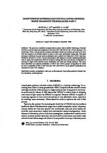
Int J Adv Manuf Technol (2001) 17:570–574 2001 Springer-Verlag London Limited
Methodology of Parametric Programming for Error Compensation on CNC Centres Z.-Q. Liu Department of Mechanical Engineering, Shandong University of Technology, Jinan 250061, PR China
Although work has been carried out on parametric programming on CNC centres, there have been few papers which focus on error compensation. Parametric programming for error compensation is presented in this paper on the basis of a simple model of machining system deflections induced by the radial cutting force in CNC turning operations. The resulting errors are introduced as compensation values to the conventional tool movements along the programmed tool path. This can result in a complex tool path. Parametric programming is applied to handle this complexity for error compensation. Keywords: Error compensation; Machining error; Parametric programming; Turning
1. Introduction Error compensation is usually implemented by moving the slides of the machine tool so that the tool tip and the workpiece have a relative motion in the reverse direction of the workpiece dimensional error [1]. This can be realised through two different techniques: one is the on-line (direct or real-time) method and the other is the off-line (indirect) method. The on-line compensation method is further divided into two subcategories: the feedback interception method, and the origin shift method [2]. The feedback interception technique is achieved by using an external personnel computer (PC) to determine the resultant errors and inject the corresponding compensation values into the feed loop of the CNC controller. Chen has previously surveyed the methods for the error compensation signals from a PC to be injected into a CNC controller during machining [3]. Several ways of doing this have been developed, which include: 1. The PC adds the compensation signals to the coordinates involved in an NC block command, and then sends the modified NC block command to CNC controller. This
Correspondence and offprint requests to: Z.-Q. Liu, Department of Mechanical Engineering, Shandong University of Technology, 73 Jingshi Road, Jinan 250061, PR China.
method has the drawback that only the errors at the endpoints of each NC block command can be corrected. 2. The PC injects compensation signals into the position feedback signal of each axis in the form of an analogue voltage through a specially developed interface card. The advantage of this method is that it requires no modifications of the CNC controller software. However, different interface cards are required depending on the feedback devices (encoder or resolver). It is also not applicable to some CNC controllers where a servomotor with a built-in pulse detector is used. 3. The PC sends the compensation signals to the CNC controller in digital form through parallel input/output ports. Manipulated by the software of the CNC controller, the compensation values are added to the control values. Using this technique, the injection can be made without interfering with the uncompensated operation of the CNC controller. However, specially developed electronic devices are required to insert quadrature signals into servo loops. For the origin shift method, the PC calculates the amounts by which the machine axes must be moved to compensate for the errors. Then, these amounts are sent to the CNC controller as compensation signals to shift the machine coordinate origins through an I/O interface [4]. This technique is usually obvious to the operators because the compensation procedure does not affect either the coordinate readings or the workpiece program being executed on the CNC controller. However, it requires modification of the programmable logic controller (PLC) unit of the CNC controller so that the compensation values can be received at the CNC end, which may not be possible on some CNC controllers. It can be concluded that the disadvantages of the on-line programming method are of twofold: the first is relative to hardware and the second is that real-time error measurement is sensitive to various disturbances (temperatures, chips, cutting fluids, etc.) occurring during the measuring (machining) process. A possible method for solving these problems is to use off-line programming [2,5]. The common way to carry out off-line error compensation is machining program modifications based on the measurement results or error model predictions. This technique does not
Methodology of Parametric Programming
require any modification of the hardware of the machine tool, and is much less expensive than the real-time method. This present paper describes an approach for error compensation using the technique of parametric programming. This approach is based on a new simple model of machine deflections induced by the radial cutting force in CNC turning operations. The dependence between the resultant errors and the independent variables (error factors) is added to the initial program. After reconstructing the tool path using the parametric programming technique, the final machining accuracy of the workpiece is substantially enhanced.
2. Parametric Programming Conventional CNC machine tool programming has been directed mainly at obtaining the required workpiece shape and size. It lacks flexibility and is inadequate for adaptation to new machining conditions. If any parameter changes from one workpiece to the next, the program must be rewritten. Parametric programming has the ability to generate general-purpose programs, including variables in computer programs written in BASIC or C. By changing variable values within a generalpurpose program, it is possible to generate new programs for a variety of workpieces. Parametric programming can be used to generate programs for extremely complicated shapes and geometry. Since parametric programs allow complex arithmetic calculations to be performed within the program, there is almost no limit to the geometric shapes that can be machined. Any shape that can be mathematically defined can be described and machined using a parametric program (with a Macro command). Machining errors usually result in a complex surface profile of the workpiece to be machined, but the technique of parametric programming has the ability to handle such complexity. Generally speaking, parametric programming features can be divided into two categories, computer-related features and CNC-control-related features [6]. The computer-related features of parametric programming remain remarkably consistent from one CNC control type to the next. Parametric programming allows access to many functions related to the CNC control (such as, tool offsets, alarms, machine buttons and switches, current modes, current axis position, timer, user’s own G, M, and T codes). However, the CNC-control-related features vary dramatically from one manufacturer to another. For the convenience of universal application, attention is focused on the computer-related features in this paper. The computer-related features allow arithmetic operations to be performed within a parametric program. Almost any operation that can be performed on a computer (or an electronic scientific calculator) can also be performed within a parametric program. Along with simple equality (=), addition (+), subtraction (−), multiplication (*), and division (/), parametric programming allows much more complicated arithmetic operations to be carried out such as sine (sin), cosine (cos), tangent (tan), arctangent (atan), exponential (exp), square root (sqrt), absolute value (abs), rounding (round), round down (fix), and round up (fup). Previously calculated variables can also be referenced in other calculations within a parametric program.
571
In this case, the current value of a variable is used as if it were an actual number. As with any computer language, parametric programming allows the combination of operations. The priority of operations (order by which operations are executed) in a combined arithmetic expression is the same as in any conventional computer program: 1. Squared brackets ([ ], note that it is not parentheses ( )) from left to right. 2. Functions (sin, cos, tan, etc.) from left to right. 3. Multiplication, then division from left to right. 4. Addition, then subtraction from left to right. All versions of parametric programming also allow looping. This technique allows commands within the parametric program to be repeated a specified number of times. Generally speaking, the way commands are executed will change during each pass through the loop. Parametric programming allows two modes of loop generation: the first uses an IF statement, while the second uses a WHILE and/or DO statement for this purpose. In its most basic form, a loop uses a counter to count up the number of repetitions. This counter is originally set to 1 (or another starting number) at the beginning of the loop. Each time the control goes through the loop, the counter is stepped. Eventually, when the desired number of repetitions is reached, the control breaks out of the loop. Loops can be used to dramatically shorten the number of redundant commands in a program.
3. Estimation of the Errors Induced by the Deflections of the Machining System It has been assumed that machining errors in the machine tool workspace can be analysed as a superposition of several quasistatic systematic effects. These effects arise from: 1. The geometric errors inherent in the machine tool. 2. Thermally induced distortions. 3. Static deflections of the machining system under the cutting force. 4. Other effects such as tool wear, workpiece clamping force effect, etc. Geometric errors and thermally induced errors have been written as parameterised models with different parameters depending on temperatures and tool tip positions [7]. Hence, the error compensation methodology proposed in this paper can be applied directly to geometric and thermal errors as well, but a detailed treatment of them will not be given here. The following section focuses on the errors induced by the deflections of the machine–fixture–workpiece–tool (MFWT) system. The modelling approach is developed for external turning on a CNC turning centre. The radial direction is represented by the X-axis whereas the axial direction is represented by the Z-axis. Thus, the Y-axis is the cutting speed direction. The workpiece is held in a chuck at one end only. In the case of turning, the tool path is confined to the x, z-plane so that all
572
Z.-Q. Liu
the error entities are functions of x and z. The error on diameter arising from the static deflections of the MFWT system under the radial cutting force can be expressed as ␦f = 2Fx(1/kt + 1/kwp + 1/ksp)
(1)
where, ␦f is the error arising from the static deflections, Fx is the radial component of the instantaneous quasi-static cutting force, kt is the overall stiffness of the tool and the structure supporting it in the X-direction, kwp is the stiffness of the workpiece on its own, and ksp is the overall stiffness of the chuck/spindle assembly including the head stock side structure. Each of the stiffnesses should be interpreted as the magnitude of Fx required to act at the cutting point so as to cause unit deflection in the X-direction at the cutting point. kt and ksp essentially depend upon the machine, fixture, and tool system. These features are relatively constant for a given turning centre. ksp continuously changes as the cutting point traverses the tool path, ksp can be predicted from finite-element analysis (FEA). However, FEA is too complex an approach for routine shop floor use. Further, in FEA, it is difficult to account for the contact deflections occurring at the various mating faces in a given machine tool assembly. In early literature from the former USSR, there were references to the fact that, at least in the case of some subassemblies within a machine tool structure, the subassembly behaves under elastic loading so as to appear to rotate rigidly about a remotely located but fixed centre (see Fig. 1). Murthy and Venuvinod later demonstrated that this observation is particularly true with respect to the spindle-head stock subassembly of a lathe [8]. This observation is used in the present work for modelling ksp for different work holding configurations. In particular, for a workpiece that is chucked at one end while the other end is free ksp = Kcsh/(R + L − z)2
finite-difference program for estimating kwp with less than 1% error even when turning complex workpiece profiles [9]. Now, combining Eqs (1) and (2), it can be shown that
(2)
where, z and L are the instantaneous axial distances of the cutting point from the free end of the workpiece and the chuck face, respectively, R is the axial distance between the chuck face and the plane normal to the spindle axis and containing the rotation centre, and Kcsh is the rotational stiffness (N·mm per radian) of the chuck–spindle–headstock assembly about the rotation centre. Finally, kwp can be determined by applying the well-known principles of the theory of elasticity since the instantaneous workpiece shape and the modulus of elasticity of the work material are easily obtained. The author has written a simple
␦f = 2Fx
再
冎
1 1 (R + L − z)2 + + kt kwp Kcsh
A very useful observation follows from Eq. (3). For a workpiece held just by chucking at one end, ␦f can be expressed as an explicit function of seven parameters: Fx, kt, kwp, Kcsh, R, L, and z. Of these, L and z are known a priori from the NC part program; kwp can be directly estimated by using the finite-difference program [9], kt, Kcsh, and R should be constants for a given machine tool with a given work holding set-up; and Fx should be constant for a given tool/work material pair, tool geometry, and cutting conditions.
4. Error Compensation in NC Part Parametric Programs and Experiments In the two-axis CNC turning centre used in this paper, the movements of the tool during cutting are confined to the x, z-plane. Now let variables #100 and #200 denote x and z, respectively, the variable set of (#100, #200) represents the tool cutting point in the machining program. Further, let #101, #102, % and #201, #202, % denote variables of the desired workpiece diameters and lengths, respectively. Then, the tool path can be represented with a function P(#100, #200) = f(#101, #102, %, #201, #202, %). Workpieces (a) and (b) in Fig. 2 have complex curved profile segments that are identical to those adopted in [10] where the workpieces were supported by the tailstock. However, in this paper, they were held by chucking at one end only and, of course, the machine tool and the cutting conditions were different from those in [10]. The tool path for workpiece (a) in Fig. 2 can be represented as P(#100, #200) =
#101
(0 ⱕ #200 ⱕ #201)
#101 − [#101 − #102]
#200 − #201 (#201 ⱕ #200 ⱕ #202) #202 − #201
#102
(#202 ⱕ #200 ⱕ #203)
#102 + [#103 − #102]
#200 − #203 (203 ⱕ #200 ⱕ #204) #204 − #203
#103
2 冑([#60]2 − [#200 − #30]2) + #20
#104
2 冑([#70] − [#200 − #50] ) + #40 2
#105 Fig. 1. The workpiece set-up on a CNC turning centre and rotation centre of a chuck/headstock assembly.
(3)
For workpiece (b):
2
(#204 ⱕ #200 ⱕ #205) (#205 ⱕ #200 ⱕ #206) (#206 ⱕ #200 ⱕ #207) (#207 ⱕ #200 ⱕ #208) (#208 ⱕ #200 ⱕ #209)
Methodology of Parametric Programming
573
Fig. 2. Workpiece geometry.
P(#100, #200) =
#101
2 冑([#60] − [#200 − #30] ) + #20 2
2
#102
achieved through programming the turning centre to the modified final diameters (represented by variable #300) by subtracting the corresponding diameter errors at each cutting point
(0 ⱕ #200 ⱕ #201) (#201 ⱕ #200 ⱕ #202) (#202 ⱕ #200 ⱕ #203)
#102 + [#103 − #102]
#200 − #203 (#203 ⱕ #200 ⱕ #204) #204 − #203
2 冑([#70]2 − [#200 − #50]2) + #40
#104
(#204 ⱕ #200 ⱕ #205) (#205 ⱕ #200 ⱕ #206)
#104 − [#105 − #104] #105
#200 − #206 (#206 ⱕ #200 ⱕ #207) #207 − #206 (#207 ⱕ #200 ⱕ #208)
#106 − [#107 − #106]
#106
#200 − #208 (208 ⱕ #200 ⱕ #209) #209 − #208 (#209 ⱕ #200 ⱕ #210)
where, #60, #70 denote the radius and (#20, #30), (#40, #50) denote positions of the centres of the arcs. Similarly, we use six variables from #401 to #406 to substitute for the six parameters: Fx, kt, kwp, Kcsh, R, and L in Eq. (3). The parameter z has been represented by the variable #200, and the variable #403 that denotes kwp is the function of variables #100 and #200. The workpiece errors on the diameter induced by the deflections of the MFWT system can thereby be represented by these variables ␦f = 2 × #401
再
冎
1 [#405 + #406 − #200]2 1 + + #402 #403 #404
#300 = #100 − ␦f
(5)
Next, the corresponding compensated tool path P(#300, #200) for the compensation of errors induced by deflections of the MFWT system is obtained by substituting Eq. (4) into Eq. (5). As shown in Fig. 3, the programmed tool path for the compensated machining process is the mirror reflection of the curve of the workpiece diameter error. Use of the compensated tool path P(#300, #200) will result in a complex outer profile to be machined, but the technique of parametric programming has the ability to handle such complexity with its powerful arithmetic operations. The compensated tool path uses a set of continuously linear segments that pass approximately through a series of compensated points, which can be easily implemented by the function of looping using the parametric programming methodology. The above compensation strategy is simple and straightforward. From a pragmatic standpoint, this procedure is computerised and stored as a parametric program in the CNC routine library. The workpiece could be divided into several sections and machined one by one if the memory capability of the control computer is a limiting factor. Experiments have been made on a two-axis CNC turning centre to verify the applicability of the compensation approach.
(4)
The workpiece errors on the diameter are due to the reduction of the depth of cut caused by the deflections in turning. Based on this observation, Kops et al. [11] suggested eliminating the deflection by setting a large depth of cut instead of the nominal depth of cut, which compensates for such reduction. Since, in practice, the datums for the CNC turning are usually related to the diameters [12], it is necessary to reset the desired workpiece diameter in a conventional machining program to eliminate the workpiece errors. Hence, compensation can be
Fig. 3. The programmed tool path P (#300, #200) in compensation machining.
574
Z.-Q. Liu
Fig. 4. The performance of the proposed parametric programming for error compensation (왕, diameter error without compensation; ✳, diameter error with compensation).
The desired workpiece geometry and tool path are shown in Fig. 2. The cutting conditions were: depth of cut = 0.5 mm, feedrate = 0.1 mm rev−1, cutting speed = 240 m min−1. Tool insert DNMG150604-QM and toolholder PDJN2525 were used. The workpiece material was mild steel. To minimise thermal effects, water was used as the cutting fluid during machining. The workpieces were first machined using the uncompensated tool path P (#100, #200) and measured on the machine tool [13]. The measurement result was fed into a personal computer where the data processing tasks, such as the calculation of the parameters (variables) in error models, the prediction of the workpiece errors and compensated tool path, were executed. Next, workpieces with the same material and geometry were machined with the compensated tool path P( #300, #200) using the same cutting conditions on the same machine. As shown in Fig. 4, the effectiveness of the proposed error compensation method with parametric programming is proved. The maximum diameter error could be reduced to about 5–7 m (which is close to the machine’s repeatability error of about 4 m) even when the maximum error associated with the uncompensated tool path was as high as 73–79 m.
6. Conclusion Parametric programming for error compensation has been presented in this paper on the basis of a simple model of machine deflections induced by the radial cutting force in CNC turning operations. The predicted errors were introduced as compensation values to the conventional tool movements along the programmed tool path. A general-purpose program for error compensation was presented using the parametric programming technique. Final workpiece machining accuracy was substantially enhanced. The performance of the proposed method of error compensation was supported by experimental evaluation. However, deflection of the MFWT system is not the only cause of workpiece errors. The compensation can be expanded
to account for other effects such as machine tool geometric and thermal errors following the proposed methodologies. References 1. J. Ni, “CNC machine accuracy enhancement through real-time error compensation”, ASME, Journal of Manufacturing Science and Engineering, 119, pp. 717–725, 1997. 2. Z. Lechniak, A. Werner, K. Skalski and K. Kedzior, “Methodology of off-line software compensation for errors in the machining process on the CNC machine tool”, Journal of Materials Processing Technology, 76, pp. 42–48, 1998. 3. J. S. Chen, “Neural network-based modelling and error compensation of thermally-induced spindle errors”, International Journal of Advanced Manufacturing Technology, 12, pp. 472–479, 1996. 4. S. Yang, J. Yuan and J. Ni, “Accuracy enhancement of a horizontal machining center by real-time error compensation, Journal of Manufacturing Systems, 15(2), pp. 113–124, 1996. 5. C. B. Amar, T. Redarce, Y. Lucas and A. Jutard, “Off-line programming and dimensional control”, Manufacturing Systems, 21(4), pp. 247–251, 1992. 6. M. Lynch, Computer Numerical Control Advanced Techniques, McGraw-Hill, 1992. 7. T. V. Vorburger, K. W. Lee, B. R. Scace Jr and F. F. Rudder, “Post-process control of machine tools”, Manufacturing Review, 7(3), pp. 252–266, 1987. 8. R. L. Murthy and P. K. Venuvinod, “Centres of rotation as an aid to the analysis of the rigidity of machine tools”, 3rd All India Machine Tool Design and Research Conference, Bombay, pp. 1– 7, 1969. 9. L. Z. Qiang, “Finite difference calculations of the deformations for multi-diameter workpieces during turning”, Journal of Materials Processing Technology, 98(3), pp. 310–316, 2000. 10. M. Shiraishi and K. Uehara, “In-process control of workpiece dimension in turning”, Annals CIRP, 28(1), pp. 333–337, 1979. 11. L. Kops, M. Gould and M. Mizrach, “A search for equilibrium between workpiece deflection and depth of cut: key to predictive compensation for deflection in turning”, Proceedings, ASME Winter Annual Meeting, PED-68(2), pp. 819–825, 1994. 12. W. Seames, Computer Numerical Control: Concepts and Progamming, 3rd edn, Delmar, ITP, 1995. 13. L. Z. Qiang, P. K. Venuvinod and V. A. Ostafiev, “On-machine measurement of workpieces with the cutting tool”, Integrated Manufacturing Systems, 9(3), pp. 168–172, 1998.