technologies and partly by the increased understanding that computers will ... This study shows that it is possible to develop ubiquitous computing applications.
ESPOO 2005
This publication is available from VTT INFORMATION SERVICE P.O.Box 2000 FI–02044 VTT, Finland Phone internat. +358 20 722 4404 Fax +358 20 722 4374
ISBN 951–38–6437–5 (soft back ed.) ISSN 1235–0621 (soft back ed.)
ISBN 951–38–6438–3 (URL: http://www.vtt.fi/inf/pdf/) ISSN 1455–0849 (URL: http://www.vtt.fi/inf/pdf/)
Esa Tuulari
Denna publikation säljs av VTT INFORMATIONSTJÄNST PB 2000 02044 VTT Tel. 020 722 4404 Fax 020 722 4374
Methods and technologies for experimenting with ubiquitous computing
Tätä julkaisua myy VTT TIETOPALVELU PL 2000 02044 VTT Puh. 020 722 4404 Faksi 020 722 4374
VTT PUBLICATIONS 560
Interest in ubiquitous computing (ubicomp) has increased dramatically during the past ten years. This trend is driven partly by the availability of enabling technologies and partly by the increased understanding that computers will eventually be everywhere and their use will change accordingly. The thesis present's work with two important subtopics of ubiquitous computing: context awareness and intelligent user interfaces. The use of personal technology devices is analysed in order to find out possibilities for obtaining and exploiting context awareness. A sensor-box has been developed that is unobtrusively integrated into a hand-held device the user is carrying continuously with them. Experiments with this device concentrate on improving the context awareness of a mobile phone used in everyday settings. With smart environment a stack-based approach is used for defining more and more detailed requirements for each subsequent level. Finally a general-purpose platform, the SoapBox, that integrates sensors with wireless communications and computing in a small and versatile module has been defined, designed and implemented. The design examples included consist of: a maze, dice, gesture control and responsive displays. The study shows that it is possible to develop ubiquitous computing applications in a controlled and consistent manner. With personal technology devices interaction diagrams are used in revealing the possibilities for obtaining and exploiting context awareness. With smart environments a stack-based approach is used in defining the technology that enables intelligent user interfaces.
VTT PUBLICATIONS 560
Esa Tuulari
Methods and technologies for experimenting with ubiquitous computing
VTT PUBLICATIONS 560
Methods and technologies for experimenting with ubiquitous computing Esa Tuulari VTT Electronics Academic Dissertation to be presented, with the assent of the Faculty of Technology, University of Oulu, for public discussion in Auditorium TS101, Linnanmaa, on April 11th, 2005, at 12 o'clock noon.
ISBN 951–38–6437–5 (soft back ed.) ISSN 1235–0621 (soft back ed.) ISBN 951–38–6438–3 (URL: http://www.vtt.fi/inf/pdf/) ISSN 1455–0849 (URL: http://www.vtt.fi/inf/pdf/) Copyright © VTT Technical Research Centre of Finland 2005 JULKAISIJA – UTGIVARE – PUBLISHER VTT, Vuorimiehentie 5, PL 2000, 02044 VTT puh. vaihde 020 722 111, faksi 020 722 4374 VTT, Bergsmansvägen 5, PB 2000, 02044 VTT tel. växel 020 722 111, fax 020 722 4374 VTT Technical Research Centre of Finland, Vuorimiehentie 5, P.O.Box 2000, FI–02044 VTT, Finland phone internat. +358 20 722 111, fax +358 20 722 4374
VTT Elektroniikka, Kaitoväylä 1, PL 1100, 90571 OULU puh. vaihde 020 722 111, faksi 020 722 2320 VTT Elektronik, Kaitoväylä 1, PB 1100, 90571 ULEÅBORG tel. växel 020 722 111, fax 020 722 2320 VTT Electronics, Kaitoväylä 1, P.O.Box 1100, FI–90571 OULU, Finland phone internat. +358 20 722 111, fax +358 20 722 2320
Technical editing Leena Ukskoski
Otamedia Oy, Espoo 2005
Dedicated to the memory of my grandmother Iida.
3
4
Tuulari, Esa. Methods and technologies for experimenting with ubiquitous computing. Espoo 2005. VTT Publications 560. 136 p. + app. 2 p. Keywords
ubiquitous computing, ambient intelligence, smart environments, context awareness, user interface
Abstract Interest in ubiquitous computing (ubicomp) has increased dramatically during the past ten years. This trend is driven partly by the availability of enabling technologies and partly by the increased understanding that computers will eventually be everywhere and their use will change accordingly. This thesis present’s work with two important subtopics of ubiquitous computing: context awareness and intelligent user interfaces. Methods are developed that firstly will make it easier to increase context awareness especially with personal technology devices and secondly enable the implementation of intelligent user interfaces as part of a smart environment. Context awareness is studied together with hand-held devices. The use of personal technology devices is analysed in order to find out possibilities for obtaining and exploiting context awareness. A sensor-box has been developed that is unobtrusively integrated into a hand-held device the user is carrying continuously with them. In this case context awareness is self-supportive, operating without the support of the surrounding infrastructure. Experiments with this device concentrate on improving the context awareness of a mobile phone used in everyday settings. Intelligent user interfaces are studied as a part of smart environments. By starting from smart environment scenarios a stack-based approach is used for defining more and more detailed requirements for each subsequent level. Finally a general-purpose platform, the SoapBox, that integrates sensors with wireless communications and computing in a small and versatile module that is easy to use in different designs and in various application domains has been defined, designed and implemented. The design examples consist of: a maze, dice,
5
gesture control and responsive displays. Each of these highlights a different characteristic of user interfaces and smart environments and their role in ubiquitous computing. This study shows that it is possible to develop ubiquitous computing applications in a controlled and consistent manner. Methods are created that make it possible to achieve the ubiquitous computing vision with technical implementations. With personal technology devices interaction diagrams are used in revealing the possibilities for obtaining and exploiting context awareness. With smart environments a stack-based approach is used in defining the technology that enables intelligent user interfaces. In both cases the method leads to technical requirements that makes it possible to implement ubiquitous computing applications.
6
Preface The roots of this work goes back to 1996 and the time when I worked in VTT’s strategic research project, EMMI, Embedded Mobile Multimedia. During that project I found Mark Weiser's articles about Ubiquitous Computing and was immediately on the hook. The vision of embedding computers everywhere was so well in-line with my own experience as I had been embedding software since 1987. Soon after that I had the pleasure of being the project manager at VTT for a long project chain that was carried out jointly with Nokia Mobile Phones. The research on context awareness and gesture recognition that we started together with Dr. Pertti Huuskonen, Dr. Jani Mäntyjärvi, Urpo Tuomela, Antti Takaluoma, Vesa-Matti Mäntylä and later also with Panu Korpipää has since grown to an importance and breadth that we could not have imagined. Being able to work without project management responsibilities for a while I was able to collect and concentrate a large part of my knowledge of context awareness, mobile computing, embedded software and user interfaces into the invention of the now widely known SoapBox platform in January 2000. Special thanks for this period goes to Mr. Mikko Kerttula, who was my boss and project manager at that time and was far-sighted enough to let us start the SoapBox development. An important part of the research concerning intelligent user interfaces and smart environments was done during my 1 year visit to Philips Research Labs in Eindhoven, the Netherlands. For this period I am most grateful to Dr. Emile Aarts for inviting me to work in his Media Interaction group as well as for his support in arranging the visit. Warm thanks goes to Dr. Evert van Loenen, who took the responsibility to host me in all practical matters during my visit to Philips Research Labs and for integrating my research in his own research in the Phenom project. Evert was also project leader for the Ambience project that received the ITEA Achievement Award in 2003. Opportunity to work with Evert in Ambience and at Philips was one of the definit highlights during this thesis work. Thanks are also due to the whole Phenom project group Dr. Elise van den Hoven, Dr. Esko Dijk, Dr. Yuechen Qian, Dario Texeira, Nick de Jong and Yvonne Burgers for
7
welcoming me to the project and providing me a “home-base” during my stay. I surely would like to share a couple of more project meetings with you. I also want to thank the whole Media Interaction group led by Maurice Groten for providing me a friendly and inspiring working environment. I wish to express warm thanks to Esko Strömmer, Arto Ylisaukko-oja and Jouko Vilmi from VTT Electronics for a long and fruitful co-operation in designing and implementing electronics with me and for me in numerous projects. Especially Arto’s role in the SoapBox development has been of utmost inportance and without his contribution my research work would not have been possible. Thank you Arto! I would also like to thank all other colleagues at VTT Electronics who have worked with me in various ubicomp projects in recent years. More specific thanks go to Sanna Kallio and Juha Kela for their enthusiastic work in gesture recognition research and for Johanna Keisala for operating as an unofficial vice project manager in the Ambience project during my visit to Philips. I want to thank my latest boss at VTT Electronics, Dr. Tapio Frantti, for organising me time to work with the thesis and for reminding me of the importance of high quality in research. I also want to thank my current employer Polar Electro Oy and manager Markku Karjalainen for providing me the possibility to carry this thesis work to its end. I am grateful to my supervising Professor Juha Röning for his time, guidance and patience during this long thesis project. I wish to express my warmest thanks to the unofficial supervisor Dr. Veikko Seppänen whose encouragement and motivation has been essential in pushing me through the difficult times that, as I have heard, are part of finalising a thesis. I am grateful to Professor Jukka Vanhala and Professor Matthias Rauterberg the official reviewers of the thesis, for their comments and suggestions to the manuscript. It really did improve during the process. Thanks for proofreading of the text into correct English go to Zach Shelby.
8
Finally I would like to thank my family, Ulla, Perttu, Tuuna, Jaakko and Sampo, for balancing my life during the many years I have spent with my post-graduate studies and with the thesis. This work has been partially conducted in the European joint research projects "Beyond the GUI" and “Ambience” under the ITEA cluster project of the EUREKA network, and financially supported by Tekes (Technology Development Centre of Finland) and VTT Electronics to which organizations I wish to express my gratitude. Kempele, Finland, March 2005 Esa Tuulari
9
Contents Abstract................................................................................................................. 5 Preface .................................................................................................................. 7 List of Symbols and Abbreviations..................................................................... 13 1. Introduction................................................................................................... 15 1.1 Background.......................................................................................... 15 1.2 Scope of the thesis ............................................................................... 17 1.3 Research problem ................................................................................ 19 1.4 Structure of the thesis .......................................................................... 20 1.5 The author’s contribution .................................................................... 21 2. From Ubiquitous Computing to Ambient Intelligence ................................. 24 2.1 Scenarios for user interfaces................................................................ 26 2.2 Technological constituents .................................................................. 28 2.3 Evolution of personal technology........................................................ 29 2.3.1 Benefits of possessing personal technology............................ 33 2.3.2 Problems of personal technology devices ............................... 35 2.4 Context Awareness .............................................................................. 35 2.4.1 Self-contained context awareness ........................................... 36 2.4.2 Infrastructure-based context awareness .................................. 38 2.4.3 Measuring the user .................................................................. 39 2.4.3.1 Gesture Recognition ................................................... 40 2.4.3.2 Biometric identification .............................................. 40 2.4.3.3 Affective computing ................................................... 41 2.4.3.4 Direct electric control ................................................. 41 2.4.4 Summary ................................................................................. 41 2.5 Intelligent user interfaces in smart environments................................ 42 2.5.1 Research prototypes ................................................................ 44 2.5.1.1 Research Initiatives..................................................... 45 2.5.1.2 Smart Homes............................................................... 46 2.5.1.3 Platforms..................................................................... 47 2.5.1.4 One-off prototypes...................................................... 48 2.5.2 Summary ................................................................................. 48
10
3. Design of Ubicomp Systems......................................................................... 49 3.1 Increasing context awareness .............................................................. 49 3.1.1 Interaction with personal technology devices ......................... 49 3.1.2 Sources of contextual information .......................................... 53 3.1.3 Analysis of existing products .................................................. 55 3.1.4 Use cases and context awareness ............................................ 58 3.1.5 The point of view of agents..................................................... 63 3.2 Enabling intelligent user interfaces ..................................................... 65 3.2.1 Experiencing intelligence........................................................ 68 3.2.2 Embedding intelligence........................................................... 69 3.2.2.1 Embedding user interfaces.......................................... 70 3.2.2.2 Embedding technology ............................................... 73 3.2.3 Summary ................................................................................. 75 4. Design Examples .......................................................................................... 77 4.1 Increasing the context awareness of a hand-held device ..................... 77 4.1.1 Requirements for the sensor box............................................. 78 4.1.2 Design of the sensor box ......................................................... 79 4.1.3 Expectations for the experiment.............................................. 83 4.1.4 Aware phone experiment ........................................................ 86 4.1.5 Contexts of mobile phones...................................................... 86 4.1.6 Identifying contexts with the sensor box................................. 92 4.1.7 Presenting the context in the experiment ................................ 96 4.1.8 Result of the increasing context awareness experiment.......... 97 4.2 Enabling intelligent user interfaces ..................................................... 99 4.2.1 The SoapBox......................................................................... 101 4.2.1.1 Electronics in general................................................ 102 4.2.1.2 Wireless communications ......................................... 103 4.2.1.3 Sensors ...................................................................... 105 4.2.1.4 Power management................................................... 106 4.2.2 Experimental designs ............................................................ 107 4.2.2.1 Responsive display ................................................... 109 4.2.2.2 Gesture recognition................................................... 112 4.2.2.3 The maze................................................................... 113 4.2.2.4 Ambient Dice............................................................ 114 4.2.3 Results of enabling intelligent user interfaces....................... 115
11
5. Beyond Experimenting for Research Purposes........................................... 121 6. Conclusions................................................................................................. 123 References......................................................................................................... 127 Appendices Appendix A: Research projects that have used the SoapBox platform but have not been included in this thesis
12
List of Symbols and Abbreviations AD
Analog to Digital (Converter)
AR
Artificial Reality
CA
Context Awareness
CRC
Cyclical Redundancy Check
DHC
Digital to Human Conversion
DOS
Disk Operating System
EEG
Electroencephalograph
EEPROM
Electrically Erasable Programmable Memory
EMG
Electromyograph
EOG
Electro-oculograph
EU
European Union
GPS
Global Positioning System
GSM
Global System of Mobile Phones
GUI
Graphical User Interface
HDC
Human to Digital Conversion
HCI
Human-Computer Interaction
HMM
Hidden Markov Model
HU
Human User
ID
Identification
I/O
Input and Output
IR
Infrared
LCD
Light Crystal Diode
LED
Light Emitting Diode
MAC
Media Access Control
MEMS
Microelectromechanical System
13
MIPS
Millions of Instructions Per Second
NR
Natural Reality
PARC
Xerox Palo Alto Research Center
PC
Personal Computer
PCMCIA
Personal Computer Memory Card International Association
PDA
Personal Digital Assistant
PT
Personal Technology
RF
Radio Frequency
SGML
Smart Graphical Mark-up Language
SoapBox
Sensing, Operating and Activating Peripheral Box
SQL
Smart Query Language
SW
Short wave radio
TEA
Technology for Enabling Awareness, project name
UI
User Interface
USB
Universal Serial Bus
WIMP
Windows, Icons, Mouse, Pointing
WLAN
Wireless Local Area Network
VTT
Technical Research Centre of Finland
14
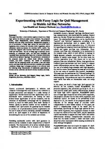
1. Introduction 1.1 Background Domestic products, automobiles and many other technical artifacts have become imbued with increasing levels of intelligence (Fig 1.1). The primary reason for the increased intelligence is the microprocessor embedded in the products controlling their operations (Baber & Baumann. 2002). This “quiet revolution” is one manifestation of the development of ubiquitous computing and has happened very much unnoticed except by those developing these products. A typical microwave oven might contain one microprocessor whereas a digital camera most probably contains several of them. However, the layman does not think of using a computer while using these domestic products.
Figure 1.1. Computers are everywhere around us. At the same time with this quiet revolution there are generations of StarTrek fans that have grown up with at least part of the ideas that we would today call ubiquitous computing (Huseman 2001). This double-role between reality and 15
science-fiction is emphasised by Lyytinen & Yoo: “one of the challenges in ubiquitous computing is to study something that does not yet exist; dream and create problems and still maintain the rigor of scientific research.” (Lyytinen & Yoo 2002). Many of the topics now belonging to ubiquitous computing are not so new, however. Long before Baber, Huseman & Lyytinen, Licklider expressed his dissatisfaction with the old-fashioned way humans and computers interacted as many computers still plotted graphs on oscilloscope screens (Licklider 1960). He was asking for something that would approach the flexibility of a pencil and a doodle pad on one hand and chalk and a blackboard on the other hand. Something quite unreachable at that time. Even more visionary was Vannevar Bush who already fifteen years before Licklider envisioned the Memex system that included personal portable memories, novel information retrieval methods and revolutionary user interface paradigms (Bush 1945). All topics that are still among the key issues of ubiquitous computing research and will be discussed also in this thesis. The reason that ubiquitous computing (shorthand version: ubicomp) was not realised already in the fourties, fifties or sixties is that it was not technically feasible. The early systems envisioned by Bush and Licklider were not realisable at their time, with the consequence that there was a 30 years delay before widespread research on the topic started. One of the consequences of this long delay has been that quite often ubiquitous computing is claimed to have started from scratch at the end of 1980’s. In reality this is obviously not the case. The rebirth of ubiquitous computing with its own name started at the end of the 1980’s at the Xerox Palo Alto Research Center, PARC, in California. The name was coined by Mark Weiser in his seminal article “The Computer for the 21st Century” (Weiser 1991). In that article Weiser describes his vision of ubiquitous computing (Satyanarayanan 2001). In short, he described Ubiquitous Computing as the third wave of computing where computers would be everywhere and every single person would possess several computers. This was seen as analogous to the development of electric motors. First there were many machines that used the same motor. Then there was one motor per machine and finally there were many electric motors in one machine.
16
With computers the same trend has been described as the three waves of computing. The first wave means that there were many people sharing one computer (the time of mainframes). During the second wave there was one computer per person (the time of the personal computer) and finally the third wave means that there will be many computers per each individual (the time of the ubiquitous computer) (Weiser 1991, 1998a). At the beginning ubicomp was a counter attack towards personal computers as researchers at PARC thought that the concept of computers should be more flexible than the one related with desktop computers (Weiser et al. 1999). However, quite soon ubicomp moved from a direct attack towards personal computers to a more abstract and general concept and came closer to its forerunners with the intention to put computers in the background and letting people interact naturally with the real world. This led to technical challenges in power consumption, user interfaces and wireless connectivity (Weiser 1991). The problem caused by the penetration of ever-smaller computers in all sorts of devices and connecting them to the physical world was emphasised by Bell and Gray (1998). Although it is already true that there are more and more computers around us, the fact is that the technology is not yet in the background and the user interfaces are not yet natural. This early development stage is stressed by several researchers, most notably by Gregory Abowd who claims that in contextawareness, an important pre-requisite for ubiquitous computing, we have only scratched the surface and many issues still need to be addressed (Abowd & Mynatt 2000). Lyytinen & Yoo specifically state that the step that still has to be taken (towards ubicomp) is to embed computers in our natural movements and interactions with our environments (Lyytinen & Yoo 2002).
1.2 Scope of the thesis Although ubiquitous computing literally means “computers everywhere” the research agenda of ubiquitous computing does not include every computer. The focus is in computers that the user uses in interacting with their environment. More generally, ubiquitous computing is concerned with technology that is located between the user and the environment when these two entities are in
17
active interaction. For the purposes of this thesis two placeholders for ubiquitous computing have been identified. Firstly, it can be found embedded in personal technology devices, like in wireless terminals and in cellular phones. Secondly, it surrounds us in our environment attached and embedded in all kinds of objects ranging from books to buildings (see Figure 1.2).
User
Technology
Environment
Personal Technology
Environment
A)
User B)
Embedded Technology
User
Environment
C)
Figure 1.2. User interacting with the environment: A) technology between the user and the environment (general case), B) personal technology near the user, and C) technology attached to the environment. Besides increasing the amount of computers we use while interacting with the environment, ubiquitous computing also promotes a new type of use for these computers. Two key concepts in realising this new type of usage are context awareness and intelligent user interfaces. Context awareness has been seen as one of the solutions for decreasing information overload, especially in relation with personal technology whereas intelligent user interfaces are an important part of smart environments (Fig 1.3).
18
Vision
Ubiquitous computing
Placeholders
Personal technology
Smart environment
Concept
Context awareness
Intelligent user interface
Figure 1.3. Placeholders and concepts for the ubiquitous computing vision. The reason for emphasising context awareness together with personal technology is the fact that with personal devices it is potentially easier to know a user’s personal preferences and use the increased awareness accordingly. In smart environments the user’s preferences are not usually known and a more general approach for improving the interaction has to be used.
1.3 Research problem The starting point for this thesis is the situation described in Section 1.1: despite over ten years of ubiquitous computing research the technology is not yet in the background and our interactions with the environment are not yet natural. Therefore, as explicitly stated by Lyytinen & Yoo (2002), the next step towards ubicomp is to embed computers in our natural movements and in interactions with our environment. The problem is then, where should we embed computers (and technology), what requirements are set for such technology, and what are the interactions and applications that can benefit from such technology and how do these benefits emerge?
19
This thesis finds answers to these questions by designing and implementing technologies that enable computers to be embedded in the user-environment interaction. This enabling technology will be developed with a top-down approach. Design examples will be implemented in order to show that the developed technology can be used in realising ubiquitous computing applications and that the implementations are feasible both from the technical and from the user interface viewpoints. The contribution of this thesis is in the development of methods and technologies a) for increasing the context awareness of personal technology, and b) in enabling intelligent user interfaces in smart environments. In a) a model is proposed for obtaining and exploiting context information in order to increase the awareness of a personal technology device. This model is used in analyzing the contexts and possibilities to obtain the context information of a personal technology device. A module for obtaining context information with sensors is developed and one operational prototype for validating the results is designed and implemented. In b) a stack-based approach for defining requirements for intelligent user interfaces is proposed. The stack consists of several levels each defining requirements for the subsequent lower level. At the lowest level the requirements are purely technical and can be implemented with a platform applicable in a wide range of applications. Using this platform four different examples are designed and implemented, each promoting intelligent user interfaces as part of smart environments.
1.4 Structure of the thesis Chapter 1 gives an introduction to the research area and outlines the scope of the thesis in relation to that area. Research questions and the contribution of the thesis in answering those questions is explained. Chapter 1 also includes a description of the structure of the work and the author’s contribution.
20
Chapter 2 analyses the current state of the art of ubiquitous computing. Most emphasis is on context awareness of personal technology devices and intelligent user interfaces in smart environments. In Chapter 3 methods are proposed for developing ubicomp systems. Firstly for increasing the context awareness of personal technology devices and secondly for enabling intelligent user interfaces in smart environments. Chapter 4 describes the technologies and design examples that have been implemented in order to verify the design methods proposed in Chapter 3. For context awareness one design example has been implemented, whereas there are four design examples dedicated to intelligent user interfaces. Chapter 5 contains a discussion about the possibilities taking the design methods proposed in this thesis into use also outside research projects and laboratories. Chapter 6 summarises final conclusions for the whole work.
1.5 The author’s contribution The ubiquitous computing research started at VTT Electronics at 1996 by reporting the current state-of the art of the research field. This work is partly published by the author (Tuulari 1997 *). This initial phase was followed by a decision to concentrate into context awareness and especially into context awareness of personal technology. Analysis of the research field continued with more emphasis on calm technology and user interfaces (Tuulari 1998 **).
___________________ *) Tuulari, E. 1997. Embedded future, from personal area networks to electronic assistants (original: Sulautettu tulevaisuus, kehoverkosta sähköiseen apulaiseen). Prosessori, 10, pp. 79–81. (In Finnish) **) Tuulari, E. 1998. Towards calm technology (original: Pinnistelystä rentoon käyttöön). Helsingin Sanomat, 17.7.1998, Tieto & Kone -sivut, p. D2. (In Finnish)
21
At the same time on the practical level the development of the sensor-box started in co-operation of VTT Electronics and Nokia Mobile Phones. The author’s contribution in the sensor-box development was the system level idea that an addon module containing the sensors would offer the best solution for the system architecture; setting the requirements for the sensor-box and designing it jointly with researchers from Nokia Mobile Phones; and managing the project at VTT Electronics that actually implemented the sensor-box. Moreover the author developed context recognition methods and signal processing software for the sensor-box. This work is published by the author (Tuulari 2000 *) and partially included in this thesis. Gesture recognition research was started alongside with the context recognition research, as the sensor-box with its acceleration sensors seemed to provide sufficient platform for research purposes. Later on the results for controlling a device with sensor information seemed so promising that a patent was applied for its use in hand held devices (Kaartinen et al. 2001 **). The gesture recognition example described in this thesis is based on these early findings but implemented with the SoapBox and adapted to controlling devices in smart environments. A discussion about the relation of gesture recognition to more traditional user interfaces was published just recently (Tuulari et al. 2005 ***).
___________________ *) Tuulari, E. 2000. Context aware hand-held devices. Espoo, Finland: VTT. VTT Publications 412. 81 p. ISBN 951-38-5563-5; 951-38-5564-3. http://www.vtt.fi/inf/pdf/publications/2000/P412.pdf **) Kaartinen, S., Kinnunen, T., Lustila, R., Salomäki, L., Liukkonen-Olmiala, T., Hynninen, T., Pirkola, J., Sippole, L., Mäntyjärvi, J., Mäntylä, V.-M., Tuulari, E. & Seppänen, T. 2001. Handheld devices. English Patent N:o EP1104143. ***) Tuulari, E., Kela, J. & Kallio, S. 2005. From remote controller to gesture control (original: Kaukosäätimestä eleohjaukseen). Prosessori, 1, pp. 39–41. (In Finnish)
22
The author’s contribution to the SoapBox development is its invention and the design of the overall concept of the general purpose platform. The electronics were designed and implemented under the guidance of the author at VTT Electronics and the author has designed and implemented part of the embedded software included in the SoapBox. Initial versions of PDA and PC programs used together with the SoapBox were designed and implemented by the author. The SoapBox was first published by the author during 2001 (Tuulari 2001 *), Tuulari et al. 2001 **)). The author invented the idea of the responsive display together with researchers at Philips Research Labs while working there as a guest researcher during 20022003. The implementation of the algorithms was done by the author while the integration of the SoapBox as well as the algorithms to the responsive display’s hardware and software was done by research colleagues working in the Phenom project at Philips Research. The contribution of the author to the maze example is in the development of the initial idea and design. The author was also involved in the development of the deterministic and synchronous communication protocol that is essential in enabling several remote SoapBoxes to communicate with one central SoapBox simultaneously without any loss of messages or delays in the communication. The ambient dice experiment was entirely designed and implemented by the author. Except making of the soft dice, which was done by Ulla Ahola.
___________________ *) Tuulari, E. 2001. Enabling ambient intelligence research with soapbox platform. Ercim news, 47, pp. 18–19. **) Tuulari, E., Ylisaukko-oja, A. & Kerttula, M. 2001. User interfaces fits in the pocket: Interconnected with a small wireless module (original: Käyttöliittymät menevät taskuun: Pieni langaton moduli yhdistää). Prosessori, 2, pp. 75–79. (In Finnish)
23
2. From Ubiquitous Computing to Ambient Intelligence During the years after 1991 ubiquitous computing research has expanded considerably and quite often researchers and research groups have used terms other than ubiquitous computing to describe their research. Some of the terms are used purely as synonyms for ubquitous computing, some describe research that is overlapping with it and some can be treated as merely subtopics to it (Fig. 2.1).
1991
year, not in scale
2004
Ubiquitous computing Calm technology Visions Pervasive computing Ambient Intelligence
Intelligent user interfaces Human-computer boundary
Affective computing Context awareness
Smart environments Wearable computers Technology whereabouts Mobile computing Mobile phones and Internet become commonplace Nomadic computing
Figure 2.1. Hierarchy for ubiquitous computing. Two research directions that have concentrated on the effects of mobility of computing devices are mobile computing and nomadic computing. Mobile computing focuses on communication, mobility and portability (Forman & Zahorjan 1994). Nomadic computing, on the other hand, concentrates more on the effects of information access and quality-of-service issues (Kleinrock 1995, Bagrodia et al. 1995). Thus it can be seen as communication–oriented, whereas mobile computing is a more general term which includes all aspects of mobile terminals. In nomadic computing it is required that two questions about the mobile terminal are known, namely "what is it?" and "where is it?” Answers to
24
these questions should make it possible to deliver relevant information effectively to the terminal (Schnase et al. 1995). One extreme example of personal technology devices is wearable computers. The problems that arise as computers are made wearable offer interesting and challenging research opportunities (Bass et al. 1997). They are often too heavy and too difficult to use and it has been difficult to find good applications for them. Presently the heavy weight is caused mainly by batteries. However, the situation is improving as batteries are becoming more efficient and at the same time the power consumption of electronics is decreasing. One novel possibility for overcoming the problems with heavy batteries is to use parasitic power taken from the user, for example (Starner 1996). User interfaces of wearable computers are often taken directly from PCs, which makes them very difficult to use while on the move. Speech recognition and hand-written text recognition have been used to alleviate these problems. However, there is plenty of room for entirely new user interface paradigms that could make the computer easy to use while also doing something else. The debate about applications for wearable computers has not been settled yet. Some believe that each type of wearable computer is useful only in a limited application area, while others are waiting for the killer application that would make general purpose wearable computers compelling for customers (Rhodes 1997). The goal of smart environments is to support and enhance the abilities of its occupants in executing tasks like when navigating through an unfamiliar environment or by providing reminders for activities (Dey et al. 1999). Context awareness has been defined as knowledge of the environment, location, situation, user, time and current task. Context awareness can be exploited in selecting an application or information, adjusting communication and adapting the user interface according to the current context (Schilit et al. 1994, Schmidt et al. 1998). Affective computing is concerned with computing that relates to, arises from, or deliberately influences emotions. Other goals are giving the computer the ability
25
to recognise and express emotions and developing its ability to respond intelligently to human emotions (Picard 1997). Calm technology is closely related to ubiquitous computing but has more emphasis on human beings instead of technology. User-computer interaction is explained with the iceberg model, where part above the surface is the center (conscious) and the part below the surface is the periphery (unconscious). The goal of calm technology is to develop technology that mainly stays at the periphery, out of the way, making the environment calmer (Weiser & Brown 1998, Weiser 1998b). Pervasive computing is sometimes said to be a synonym for ubiquitous computing. The vision includes the creation of environments saturated with computing and communication capabilities together with graceful integration with human users (Satyanarayanan 2001). The most recent of the visions is Ambient Intelligence. According to (Aarts & Marzano 2003) as digital technologies become increasingly pervasive, we may find ourselves living, with almost invisible, intelligent interactive systems – an Ambient Intelligence that could soon form a natural part of our everyday existence.
2.1 Scenarios for user interfaces As the future forecasted in these visions is not yet here, the use of scenarios as a tool for illustrating how the user would interact with the technology has been widely used and generally accepted. Already the title of Licklider’s 1960 article “Man-Machine Symbiosis” gave a strong impression of his idealistic user interface where “computers are used for analytical and precision tasks that they are most suitable for, whilst tasks requiring a nervous system with several parallel channels is left to the man”. In building systems that would integrate the positive characteristics of both man and machine Licklider sees the communication problematic as “the speed and language of the entities are quite different” (Licklider 1960).
26
Bush, on the other hand, envisioned that the system would have a memory that could hold everything a person chooses to record and that the data would be recorded in such a manner that it could be searched by using hints and associations (Bush 1945). Bush also developed ideas for user interfaces that would be easy to use even while the person is walking or otherwise moving around. In 1991 Weiser used a more intimate and personalised scenario by introducing a female called Sal. In the scenario Sal wakes up in the morning and undergoes a sequence of experiences ranging from windows that record and illustrate the traffic on the street to electronic telltales that inform her about fresh coffee at the coffee machine. The explicit use of computers by Sal is very limited as computers are embedded in the environment and the interactions with them do not resemble the use of any ordinary computer. One way to illustrate future user interfaces has been to compare them to a butler (Negroponte 1997). This scenario includes the fact that the interface to a butler is very casual, as he knows almost beforehand what services are expected. This casualness is based on the butler’s knowledge of all the things that are happening in the house. More down-to-earth thinking is provided by Norman (1998) who suggests that letting humans be humans and computers be computers is the best way to proceed (Norman 1998). As everyday life has changed dramatically since 1990 with the introduction of mobile phones, portable computers and the Internet, there has also been a slight change in the scenarios. In recent scenarios given, for example, by Aarts & Marzano (2003) it is not anymore the computer that is everywhere and hidden in the environment, but the services offered by the computers. Moreover, the interaction with information is ambiently available to the user wherever they happen to reside. Although the scenarios are useful in illustrating the user’s role in the ubiquitous computing vision, they are too abstract to be really useful in realising the vision. Abowd et al. (2002b) tries to give a more structured view of the requirements by defining three goals that have to be realised in order to reach the vision. First, the everyday practices of people must be understood; secondly the world must be augmented with heterogenous devices offering different forms of interactive experience; and thirdly networked devices must be orchestrated to provide for a holistic user experience.
27
2.2 Technological constituents In the early days of ubiquitous computing research there was a need to study and develop basic technologies, like cheap and small computers and displays, lowpower consumption electronics and wireless networking (Weiser 1993, Demers 1994). Besides these technical topics the integration of technology and user interfaces to interact with the technology were on the research agenda (Want et al. 1995). Forman & Zahorjan (1994) define mobile computing as “the use of portable computer capable of wireless networking” and list the three most essential properties as communication, mobility and portability. For each of these properties they further list topics of interest like, low bandwidth, location dependent information, low power and small user interfaces to mention just a few. Currently these technologies are partially available off-the-self, which has led to a shift in the research agenda. This shift has happened especially towards sensors for gathering information (Saha & Mukherjee 2003). Banavar & Bernstain (2002) even claim that any introduction of ubiquitous computing implies the introduction of sensors. They also point out that the inclusion of sensors has an impact on social structure no matter how unobtrusive they are. Satyanarayanan remarks that a pervasive system that strives to be minimally intrusive has to be context aware (Satyanarayanan 2002). Research has also been done in understanding the disappearance of computers better. Tandler et al. (2002) have distinguished two types of disappearance. In physical disappearance computers become small enough to be invisibly embedded in all kinds of devices. In mental disappearance humans do not perceive the devices as computers but as embedded elements of augmented artifacts in the environment. Want categorises current ubicomp research projects into two groups: personal systems, which include mobile and wearable systems, and infrastructure systems, which are associated with a particular physical locale (Want et al. 2002). He also states that in both categories novel user interface modalities are necessary.
28
Starner, one of the founders of wearable computing research, defines the ideal attributes for a wearable systems as: constant access to information, sensing and modelling of contexts, adaptation of interaction modalities based on context, and augmentation and mediation of interaction with the user’s environment (Starner 2001). Charting the past, present and future of ubicomp research Abowd divides the current challenges into three main themes: natural interfaces, context-awareness, and capture and access to experiences (Abowd & Mynatt 2000). The rest of this chapter will analyse the research on context awareness of personal technology and intelligent user interfaces in smart environments in more detail. The goal of this analysis is to form a base on which to build further research on these topics.
2.3 Evolution of personal technology The development of personal technology has proceeded side-by-side with research prototypes and commercial products. In retrospect it is difficult to say which one has been in the lead. Commercial pressures more than academic interest have been the driving force for more efficient batteries and more easyto-use user interfaces, for example. Topics that have been addressed by researchers include quality of service, adaptive user interfaces and distributed computing, to name a few (Imilienski & Korth 1996). The most influential research prototypes in the personal technology area have been ParcTab (Fig. 2.2) and Active Badge (Fig. 2.3). They have some common features, such as location awareness, although their underlying motivation is quite different.
29
Figure 2.2. ParcTab (http://www.ubiq.com/parctab/pics.html). The goals of the ParcTab project were (1) to design a mobile device, the ParcTab, that enables personal communication; (2) to design an architecture that supports mobile computing; (3) to construct context-sensitive applications that exploit this architecture, and (4) to test the system in the office community (Want et al. 1995). ParcTab does not include any sensors. Location awareness is obtained by identifying the transmitter with whom the Tab is communicating. There is one transmitter per room, which makes it easy to determine the location of the Tab to the accuracy of one room (Schilit et al. 1994). Continuous communication between the Tab and the server also makes it possible for the server to know the location of all the Tabs. The user interface consists of a rather small display and just three buttons. The design of the device is symmetrical which is exploited in such a way that it is possible to change the orientation of the display 180-degrees with a menu selection. This makes the Tab suitable for both right and left-handed users (Want et al. 1995).
30
Figure 2.3. Four types of Active Badges (http://www.uk.research.att.com/thebadge.html). The Active Badge has two features that are related to context awareness. Firstly, it is location aware either in room resolution or in more precise resolution with a research prototype. The second feature is that power down operation is activated when the built-in light sensor detects that it is in darkness (perhaps in a drawer). Location awareness was utilised from the very beginning, as the initial application of Active Badge was to assist the telephone receptionist in locating people in the office (Want et al. 1992). Terminology There are several terms that are commonly used when discussing mobile devices, namely: mobile terminal, hand-held device and personal technology. A mobile terminal refers to a device that has a wireless connection to a server machine or to a network. A mobile phone is a good example. Hand-held device means a device that is carried and operated in the hand. It can have wireless communication capabilities but it is also operational without them. PDA devices fall into this category. Personal technology refers to all modern electronic equipment that is carried around by people. This is the largest category of products, including for example Walkmans and heart rate monitors.
31
The use of the terms is usually quite liberal. The definitions of the terms are also somewhat overlapping. Table 2.1 positions some of the existing personal technology devices. A more detailed analysis of these devices is presented in Chapter 3. Table 2.1. Defining some of the most well known products. xxx = first grouping, xx = second grouping, x = third grouping, empty = does not belong to group. Mobile terminal
Hand-held device
Personal technology
Wristwatch
xxx
xx
Heart-rate monitor
xx
xxx
Mobile phone
xxx
xx
x
GPS-navigator
x
xx
xxx
xx
xxx
xx
xxx
Walkman PDA
x
There is a continuous debate on how these devices will evolve in the future. Some have predicted that part of them or all devices will be integrated in wristwatches. The integration of wristwatches and mobile phones would become a wristfone (Pescovitz 1998), for example. More revolutionary thinkers predict that future products will be integrated into our clothes (Gershenfeld 1996). One extreme of this trend was reached at the beginning of 1999 as Professor Kevin Warwick implanted a microchip into his arm. He was the first human being to do so if microchips implanted in order to overcome some medical disorder, like heart disease or weakened hearing are not counted. Still there are researchers who believe that instead of one integrated device there will be a vast variety of devices each specific to some limited task. A forecast expressed already by Weiser (1991).
32
Some integration has already taken place, as the heart-rate monitor usually includes a watch and some of the more expensive mobile phones include a GPSnavigator (http://www.benefon.com/catalogue/gsm_gps 16.12.2003). Recently there has been news even about wristwatches that include a GPS-navigator (http://www.casio.com 16.12.2003). The future of these devices in the miniaturisation or integration point-of-view will not be discussed further, as it is not in the scope of this thesis. The services that these devices offer to the user are more interesting, along with the problems that are associated with the use of hand-held devices.
2.3.1 Benefits of possessing personal technology Fogg has studied computer functions and found three types of different functionality that they offer (Fogg 1998). The essence of these functions is in increasing capabilities, providing experience and creating relationship. There are two main motives for increasing capabilities. The first is to overcome some, usually physical, disability. The second is to augment the capabilities of a normal healthy person, Figure 2.4.
33
Capability
Augmented
Normal
Reduced
Person with disabilities
Normal person
Person with personal technology
Figure 2.4. Normalising versus augmenting human capabilities. In both cases we can divide the use of the device into two types, regular and occasional. The use of binoculars is clearly occasional and augmentative whereas the use of a pacemaker is regular and normalising. One interesting phenomenon is that what we consider normal is steadily increasing capability. In many cultures people carrying no devices with them are nowadays more abnormal than those carrying one or two personal technology devices. The effect of this trend is quite considerable. For example, the use of a mobile phone increases one's mobile telecommunication capabilities drastically compared to the situation where mobile phones do not exist. Some of the negative effects of this development are discussed by Araya (1995). He warns us about a new kind of otherness that arises as people are not mentally in the same place as they are physically. On a larger scale, this critique is related to the well-known critique of technology dependence presented by for example Orwell in his famous book “1984”.
34
2.3.2 Problems of personal technology devices One of the key problems with personal technology devices is their user interface. There is usually no room for a normal WIMP interface and if there is, the small size of the keyboard and display makes the use of the device quite cumbersome. In the HCI research community this problem has been studied very actively during the last few years. The belief that speech recognition will solve the problem is common. However, some researchers think that talking to the device is so unnatural that it cannot be the solution and that new paradigms are needed (Dam 1997). One emerging possibility is to make the device more aware of its current environment and operational state and restrict the interface accordingly. This decreases the amount of interaction needed with the user, thus decreasing the need for complicated interaction gadgets, thus making them eventually unnecessary. Devices should not only be easy to use, as was the goal some years ago, but there could be devices that need no explicit use at all. One example of this sort of device is an electronic water tap that notices hands put below it and opens the valves to give water. After the hands are taken away it closes the valves automatically. There is no need for the user to operate the tap, they only need to wash their hands. An electronic water tap is, of course, not a hand-held device, but it is adequate to illustrate the development that is already ongoing in modern user interfaces.
2.4 Context Awareness The previous section has discussed about some of the most advanced modern hand-held devices. It was noticed that context awareness has been used almost only as location awareness to enhance the user interface. This minimal use of context awareness is due to the fact that the devices were not designed to be context-aware. The premise for exploiting context awareness is to first obtain information about the context. This section takes a close look at research which includes increasing context awareness as one of the basic research problems.
35
Having said that it must be admitted that location is often the most valuable form of context awareness, especially as far as mobile devices are concerned. HCI, on the other hand, was declared to be one of the most problematic areas of mobile devices in the previous chapter. These facts suggest that using location awareness in improving HCI is a good starting point for exploiting context awareness in highly portable hand-held devices. Here context awareness is divided into two parts, depending on the method used to achieve it. The first part consists of context awareness that is achieved by the device itself without any outside support, called self-contained context awareness. The second part includes those context awareness methods that need some support from a larger system or infrastructure and are called infrastructure-based context awareness.
2.4.1 Self-contained context awareness This section presents works that deal with context aware hand-held devices that recognise their context without any external support. TEA is a multi-national research project partly funded by the EU (Schmidt et al. 1998). One of the participants in TEA is TecO. Researchers at TecO emphasise that "there is more to context than location". They have exploited environmentsensing technologies for automated context recognition. They also propose to use combined sensors for recognition of higher level contexts. According to their reasoning, the most notable use of context awareness is the adaptation of user interfaces to given conditions in specific situations. They also note that context awareness is hardly applied in mobile user interfaces yet. To structure the concept of context they propose two categories: human factors and the physical environment, with three subcategories for each. For the former they are: information on the user, social environment and task, and for the latter; location, infrastructure and conditions (see Fig. 2.5). Context history is orthogonal to these categories and provides additional information of past incidents and makes it easier to predict new contexts.
36
Figure 2.5. TEA structure for contexts. The selection of application in a hand-held device could be based on context awareness. For example, it would be useful to see the shopping list while in a grocery store. In the constructive part of the work TecO researchers have developed a prototype of a PDA device that senses the orientation of the device and selects the display mode between portrait and landscape automatically. Wearable computers The most advanced wearable computers are much more than scaled-down office PCs. For example, Steve Mann has developed wearable computers that include a wide variety of sensors for measuring both the environment and the person wearing the computer (Mann 1996). This makes the wearable computer aware of its environment. The sensing in Mann's wearable computer consists of sensors for measuring the state of the user, i.e., heart rate and temperature, as well as cameras for "seeing the same as Steve sees" (Gershenfeld 1999).
37
One unique property of Mann's wearable computer is that it is more an information provider than a consumer. Unlike location-based reality augmenting notes that will be described in the next chapter, Mann's wearable computer acts as a mobile information source offering information about the context of the device and of the user (usually Steve) to the rest of the world through the Internet. The location of the information is not fixed to any absolute place but moves along with Steve. We can assume that this type of information selection is in some sense more relevant than selecting information only by location. For example, for relatives and friends, context information related to Steve is more interesting than information related to some specific fixed location.
2.4.2 Infrastructure-based context awareness This section presents works that deal with augmenting the environment, in order to improve the context awareness of a hand-held device. There are several possibilities for doing the augmentation. For example, adding RF or IR Tags to the building could provide location information for the hand-held device. Connecting the hand-held device wirelessly to the office's intranet, for example with WLAN, could provide timely information about meetings, menus, etc. Augment-able reality Rekimoto, from the Sony Computer Science Laboratory, has developed an environment that supports information registration to real world objects (Rekimoto et al. 1998). He points out that current augmented reality systems that do not dynamically attach information to objects are essentially context-sensitive browsers. Based on his experience with the prototype system, he feels that the key design issue in augment-able reality is how the system can gracefully notify situated information. The current practice of overlaying information on a seethrough heads-up display is too obtrusive. As a more handy approach, Rekimoto suggests small LEDs for eyeglasses. After having seen the notice of situated data, the user can browse the data via a palmtop or wrist-top display.
38
Stick-e notes Brown from Kent University states that the present trends in hand-held computing devices are making context-aware applications very interesting (Brown et al. 1997). His opinion is that the creation of context-aware applications has to be made easier. Specifically, the aim is to make the creation of context-aware applications as easy as making web documents. The technology proposed by Brown is based on stick-e notes, which are electrical equivalents to post-it notes. A stick-e note consists of two parts, a context and a body. Whenever the context is matched, the body is triggered. The context is described by location, objects that need to be with the user, time and orientation. The notation for writing stick-e notes is SGML, which should make it easy to use even for non-programmers. Smart Rooms Pentland, together with his group at the Media Laboratory at the Massachusetts Institute of Technology, has developed computer systems for recognising faces, expressions and gestures (Pentland 1996). Pentland claims that computers must be able to see and hear what we do before they can prove truly helpful. This new technology has enabled them to build environments that are not deaf and blind like current computers. Areas that they call Smart Rooms are equipped with computers that can assess what people in the room are saying or doing. Visitors in the room can use actions, voices and expressions to control computer programs, browse multimedia information or venture into realms of virtual reality. In Smart Rooms the user does not need to carry any external devices, all the computers are in the room and all computing is done by the infrastructure.
2.4.3 Measuring the user Context sources can be divided into two groups: the environment of the user and the user themself. Context awareness is usually more related to environment, although some wearable computers have the ability to measure certain attributes of the user as well. This section describes projects that concentrate on measuring the user.
39
2.4.3.1 Gesture Recognition One special field of context awareness is gesture recognition. It has been studied both as an HCI problem (Nielsen 1993) and as a pattern recognition problem (Lee & Kim 1998). Depending on the technology that is used, it is either self-supportive or infrastructure-based. The applications that are used vary from conducting music to recognising American Sign Language. Most of the works are video-based and use a video stream as an information source (Starner et al. 1998). The second most used method is to incorporate acceleration sensors into the device, in order to recognise the gestures that the user makes (Sawada & Hashimoto 1997). The reason to include gesture recognition as a sub-field of context awareness is not straightforward. The motivation is, however, rather clear when looking at the situation from the devices’ (or applications’) point of view. It should somehow react to changes in its location, for example. In the same manner, it should react as the hand is moved from one position to another. As seen from the hand-held device, there is no difference if the device is moved together with the user or in relation to the user. It detects a change in its environment and should react to it. What the desired reaction is depends, of course, on the detected change. 2.4.3.2 Biometric identification Identifying the user by measuring some physiological parameters is known as biometric identification. There are several parameters that are suitable for this purpose. A method that uses fingerprint identification is the most suitable for portable devices. Siemens has already demonstrated a smart card that uses this technology as a password. Iris scanning is claimed to be the most reliable method, because there are no two identical iris-scans. The drawback is that a high quality camera is needed. Hand-held devices are often personal and user identification is therefore also a security feature. There are, however, situations like in an office, where there could be several users for the same device. In this type of use it is important that the device adapts to the user. Different users might prefer different application programs or different kinds of user interfaces even in the same situations. Identification of the user could make the adaptation automatic.
40
2.4.3.3 Affective computing Measuring and recognizing the mood of the user is said to be a key step towards giving computers the ability to interact more naturally and intelligently with people (Vyzas & Picard 1998). Rosalind Picard, together with her colleagues at MIT, has studied computing that is related to human emotions and named it "affective computing" (Picard 1997). The first part of affective computing is to understand the various alternatives that people use in expressing their emotions. Some forms are apparent to other people, like gestures and voice intonation, while others are less apparent, like heart rate and the blood pressure. The second part of affective computing is to develop methods for measuring and recognising human emotions. Finally, the third part consists of synthesising emotions in computers. 2.4.3.4 Direct electric control Controlling computers directly with the body's electric signals is an option that is most familiar from science-fiction literature and movies. However, the possibility has also interested some scientists. Research into the use of EOG, EMG and EEG to control computers has been conducted at least in accordance with disabled users (Lusted & Knapp 1996). If these methods prove to be useful, they may provide an effortless way to communicate with computers.
2.4.4 Summary The design and implementation of research prototypes has been the most commonly used method in context awareness research. Both self-supportive prototypes and prototypes that possess infrastructure-based context awareness have been described. The division of contexts into several parts, at least into the environment and the user, is widely accepted. However, the general underlying principles of context awareness have not been sufficiently addressed. Chapter 3 presents a framework that is used in this thesis for analysing the principles of context awareness and methods for obtaining and exploiting contextual information in hand-held devices.
41
2.5 Intelligent user interfaces in smart environments From the human-computer interaction point-of-view the ultimate goal of ubiquitous computing is calm technology where the concept of interfaces moving seamlessly between the foreground and background of our attention has a central role (Weiser & Brown 1998). Keeping the interface most of the time in the background of our consciousness should considerably decrease the burden and mental load caused by the system on the user. As a classical example Weiser uses the inner office window, which unobtrusively offers information about activities outside (in the corridor) to the person sitting in their room. The term Calm Technology was invented by Mark Weiser (Weiser 1998a, Weiser & Brown 1998), as the ubiquitous computing experiment did not succeed in creating invisible user interfaces. "Our focus [in ubicomputing] was on invisibility, at disappearing the 'computer' to let the pure human interaction come forward. I must admit to you, largely we failed. ... we did not succeed at creating the invisibility we craved. We did not because we did not appreciate the enormity of the challenge, primarily the challenge of a proper model of the human being for whom we were designing", as Weiser confessed in a keynote speech in 1998 (Weiser 1998b). The same unobtrusiveness is emphasised by Negroponte (1996) as he has expressed a wish that devices and services should resemble a butler, knowing our habits and preferences and still act unobtrusively in the background. With desktop user interfaces based on the GUI and WIMP metaphor this type of background interface is difficult to achieve, which calls for new types of interface modalities and user interface paradigms. However, Baber has pointed out that for certain tasks there are features in WIMP that can and should be applied also to ubiquitous computing (Baber & Baumann 2002). For example, using icons to clearly map user actions to system functions or providing multiple views of an application through different windows are among the successful features in WIMP and should not be discarded when inventing new ways to interact with the computer. Liebermann has noticed that interactivity, which has long been a goal for good human-computer interfaces, leads to inefficiencies as the user and the computer are working alternately (Lieberman 1997). Kuivakari has proposed that a
42
solution could be found by adding more computing resources to the user interface making the interface more intuitive and requiring less attention by the user (Kuivakari et al. 1999). Research on new user interface paradigms has provided new ways to interact with the environment (Abowd & Mynatt 2000). One common approach is to add sensors to the device in order to a) make one hand operation easier (Björk et al. 2000) or b) to make the use of the device more naturally resemble interaction with real-world objects (Harrison et al. 1998, Masui & Siio 2000). One definition of smart environments is given by Satyanarayanan as he states that the essence of pervasive computing is in the creation of environments saturated with computing and communication capabilities together with graceful integration with human users. It subsumes the research agenda of mobile computing including the following additional research topics: effective use of smart spaces, invisibility, localised scalability and uneven conditioning (Satyanarayanan 2001). Banavar & Bernstain illustrate a future scenario and highlight three key characteristics of ubiquitous computing: 1) task dynamism, 2) device heterogeneity and resource constraints, and 3) computing in a social environment (Banavar & Bernstein 2002). As a research challenge they identify semantic modelling; building of the software infrastructure, and the development and configuration of applications. According to Dey et al. (1999) the goal of smart environments is to support and enhance the abilities of its occupants in executing tasks like when navigating through an unfamiliar environment or by providing reminders for activities. In order to do this the environment has to be able to detect the current state or context in the environment and determine what actions should take place based on this information. In other words, the environment has to know what is going on in it and how to provide assistance to the user. Saha & Mukherjee (2003) claim that pervasive computing is a superset of mobile computing, that besides mobility also requires interoperability, scalability, smartness, and invisibility in order to provide seamless access to computing whenever users need it. According to (Saha & Mukerjee 2003) there
43
is a hierarchy where context awareness is needed to create intelligent environments, which subsequently are needed to create pervasive computing. On the implementation level sensors, signal processing and pattern recognition forms the basic enabling technology for realising applications. This hierarchical structure is illustrated in Fig. 2.6. The boxes are not aligned in the diagram, as there can exist context awareness without sensors, for example.
Pervasive Computing
Smart Environment
Context Awareness
Pattern Recognition
Signal Processing
Sensors
Figure 2.6. Hierarchy from sensors to pervasive computing.
2.5.1 Research prototypes Research prototypes for smart environments range from rather simple sensorbased user interfaces to large research initiatives striving towards university or company wide ubicomp infrastructures. Somewhere between these are smart home laboratories and technology platforms that can be used to implement several different prototypes. 44
2.5.1.1 Research Initiatives Smart environment research is often carried out by a large initiative where several projects or research partners co-operate in building a joint infrastructure for providing more research momentum. A recent summary of such initiatives is given by Saha & Mukerjee (2003): Aura aims to design, implement, deploy, and evaluate a large-scale computing system demonstrating a “personal information aura” that spans wearable, handheld, desktop, and infrastructure computers. Endeavour focuses on the specification, design, and prototype implementation of a planet-scale, self-organising, and adaptive “information utility”. Oxygen envisions a future in which computation will be freely available everywhere, like oxygen in the air we breathe. The implementation is based on mobile and stationary devices connected by a self-configuring network. Cooltown extends web technology, wireless networks, and portable devices to create a virtual bridge between mobile users and physical entities and electronic services. EasyLiving addresses middleware, geometric world modelling, perception, and service description in order to develop an architecture and related technologies for intelligent environments. Portolano emphasises invisible, intent-based computing, which infers user’s intentions via their actions in the environment and their interactions with everyday objects. To make Saha & Mukerjee’s list a bit more comprehensive two more examples should be added. The first is ambient intelligence driven by Philips Research and concentrating on combining ubiquitous computing with social intelligence (Aarts & Marzano 2003). The second addition, Flow, is an initiative by IBM and focuses on developing applications that can run on any platform and flow smoothly from one platform to another (http://www.ibm.com 18.12.2003).
45
2.5.1.2 Smart Homes In some cases the smart environment research initiatives have been supported by special facilities that have been developed in order to assist integration and testing of the technology and applications. As examples of such research environments one from the USA and three from Europe are listed. AwareHome at Georgia Institute of Technology focuses on developing applications and technologies in a home environment that perceive and assist the occupant. The building contains three floors: the technology is located in the basement; the second floor showcases all the demonstrations and the main floor is occupied by students working in various projects. The living memory box, gesture pendant and indoor location tracking are some of the prototypes already developed and demonstrated in the AwareHome (http://www.cc.gatech.edu/fce/ahri/ 12.2.2004). HomeLab developed by Philips is located at the Philips research campus in Eindhoven, the Netherlands. It is a normal Dutch house integrated to an office building. When entering into it from the front door it looks like a normal home whereas entering from the back door reveals that it is actually an extension to a research lab. The HomeLab is used by Philips to carry out user tests for new products, product prototypes and product concepts in a home like test setting. Another important use for the house is to showcase new research prototypes. Some of the most recent prototypes demonstrated in the HomeLab are memory browsing, a digital jukebox and a context aware remote controller (Aarts & Marzano 2003, http://www.research.philips.com 12.2.2004 ). The InHaus located in Duisburg, Germany, and managed by a consortium of several companies has as its goal to integrate different technological solutions within the InHaus. In more detail the goal is, e.g. to study interoperability, usersystem interaction and to test technology acceptance. The InHaus extends the concept of home as it links the house to the outside world by the Internet and includes a connected car in the research setup (http://www.inhaus-duisburg.de 12.2.2004). The Living Tomorrow II consortium has two buildings, one in Brussels and one in Amsterdam. Living Tomorrow is a demo building containing a home (with a
46
home office) and an office. It shows various technologies from companies sponsoring the house. Technologies on show at the moment include broadband Internet, furniture that is easy to move and reconfigure, speech recognition and synthesis and an intelligent mirror (http://www.livtom.be 12.2.2004). 2.5.1.3 Platforms The development of ParcTab was an important part of the ubiquitous computing research done at Xerox PARC in the early 1990’s (Want et al. 1995). Nowadays the development of complete hand-held devices for research purposes has largely ceased because off-the-self PDA’s offer a good enough hardware platform as well as an open software interface for writing own applications. However, for ubiquitous computing research purposes several research prototypes that extend the capabilities of existing devices have been built in recent years (Dey 2001, Hincley et al. 2000, Schmidt et al. 1998). Extensions have often included sensors but location tags have been used as well. The goal of the Smart-Its project is to develop a range of small, embedded devices as platforms for the augmentation and interconnection of artefacts. These devices Smart-Its, in general integrate sensing, processing and communication with variations in perceptual and computational capacity (Holmquist et al. 2001). One of the research targets is to investigate the correlation of context across artefacts as a foundation for collective functionality. At KTH students have used SmartBadges for experimenting with ubiquitous computing (Beadle et al. 1997). As the name implies, a SmartBadge is a badge having more intelligence than a normal badge. The size of the SmartBadge is large enough to include a PC-CARD slot for a WLAN-card. The SmartBadge architecture is based on servers where all information is gathered for further analysis. Example applications are controlling access to rooms and profiling the usage of some specific door. The MicroAmps project at the University of California aims at greating dust sized computing elements that could be used for example in military manouvers (Warneke et al. 2001). Their current implementation is cubic-inch sized but according to the researchers MEMS technology will make it possible to squeeze
47
the same functionality into the size of a dust-particle. The researchers are not planning to use RF communication in dust-size devices because there is no room for an antenna and the components for IR communication are also cheaper. 2.5.1.4 One-off prototypes There are a lot of research prototypes that, according to published research articles, have been used only once or twice in ubicomp research. Compared to those vast research initiatives described earlier these are, of course, quite limited in scope but sometimes offer interesting insight into some focus area. In one practical example smart environments have been realised by embedding computational intelligence into everyday objects such as toys, clothing, furniture and even balloons (Resnick 1996, Hawley et al. 1997). Another example of an artefact that is well suited to the smart environment concept is the digital baton, which enhances user – real world interaction by adding sensors to the user device (Gershenfeld 1996). For this project the user device is the baton and the environment is the orchestra that is controlled with the baton.
2.5.2 Summary Currently ambient intelligence, calm technology and pervasive computing are on a stage where research prototypes are built and demonstrated as part of smart environments. These prototypes include a hierarchical set of technologies (Fig. 2.5), like sensors, signal processing, novel user interfaces etc. The following chapter shows that starting from the vision it is possible to set definite hierarchical requirements for each level and even verify that these requirements are met on each level. Moreover it is claimed that satisfying the requirements on the lowest technical level with a reusable general purpose platform it is possible to enable a large number of different designs that will meet the requirements also on the highest vision level.
48
3. Design of Ubicomp Systems 3.1 Increasing context awareness Overall, trials to improve the context awareness of personal technology devices have been rather modest so far. The devices do not adapt to changes in the environment and in the usage situation. One reason for this is probably that there has not been enough knowledge about where to find contextual information and how to exploit this information in the operation of the device. In this chapter some solutions to these problems are proposed. Firstly, the interaction models of personal technology devices are analysed and the associated information flows examined. Secondly, the chapter presents how use-case diagrams and scenarios can be used to find ways to utilise context information.
3.1.1 Interaction with personal technology devices Rekimoto & Nagano, who have analysed computer usage, divide HCI into four different styles (Fig. 3.1) (Rekimoto & Nagano 1995). In a traditional GUI interface the user interacts with the computer and with the real world but these do not interact with each other (Fig. 3.1a). In virtual reality the user cannot interact directly with the real world because they are surrounded by the computer-world created by the Virtual Reality system (Fig. 3.1b). In the ubiquitous computing style the user interacts directly with the real world and with several computers that are located in the real world (Fig 3.1c). Finally, in augmented interaction part of the user interaction with the real world is captured and augmented with a computer that forms a wall between the user and the real world (Fig. 3.1d). Although these styles cover a large part of HCI, none of the styles is sufficient for describing the user interaction that is common with personal technology devices.
49
Figure 3.1. Comparison of HCI styles involved in human-computer interaction and human – real world interaction. One way to understand personal technology (devices) is to treat it as a connection between the user carrying it and the rest of the world. In this respect it is quite close to the augmented interaction style, shown in Figure 3.1d). However, this style is too simple for describing the interaction of a user carrying hand-held devices with the real world. For example, the fact that most of the interaction between the user and the real world goes past the computer is not well explained by the augmented interaction style. Figure 3.2 illustrates a more comprehensive interaction model. This model is sufficient for describing all interactions with a personal technology device. The model purposefully divides the real world (R in Figure 3.1) into two parts, artificial reality (AR), and natural reality (NR). It also restricts the computer (C in Figure 3.1) to include only personal technology (PT) devices. 50
Dividing reality into natural (NR) and artificial (AR) parts is important from the context awareness point of view. As seen in Chapter 2, context aware systems can be divided in two categories according to their interaction with the infrastructure. Clearly, this type of infrastructure belongs to artificial reality.
AR
PT-Device Human User
NR
Figure 3.2. Interactions as the human user is carrying a personal technology (PT) device. AR = Artificial Reality, NR = Natural Reality. Drawn a bit differently (Fig 3.3) it is readily noticed that this interaction model represents Fig 1.2b on a more detailed level. The role of personal technology as an extension for the user and as a mean for the user in augmenting their capabilities is emphasised. The human senses in obtaining information as well as the limited possibilities for a human to output or express information severely restricts their abilitities to communicate with the environment. This is true for all three entitities the user interacts with.
51
Environment
AR
Human User
PT-Device
NR
Figure 3.3. Personal technology between the user and the environment. A human being can easily sense the level of light in an outdoor situation but they cannot determine the time or date without technical assistance (Table 3.1). On the other hand it is easy for a human being to notice if some room is crowded for example whilst for a device this is not an easy task. Currently the importance of personal technology is becoming more and more important in providing a channel for communicating through artificial reality. For example, telecommunications and digital recordings are only usable with the right kind of technical assistance, which of course is not allways personal. Table 3.1. Example interactions in Figures 3.2 and 3.3. Interaction
Left-right
Right-left
HU – AR
Starting a microwave oven
Watching TV
HU – NR
Talking
Tasting food
HU – PT
Switching background light on
Feeling vibration alarm
PT – AR
Transmitting a text message
Detecting an RFID-tag
PT – NR
Activating an audible alarm
Sensing the level of light
AR – NR
Setting a message to an info screen
Measuring temperature
52
With this model it is emphasised that interaction with hand-held devices takes parts from many different interaction styles. A continuous intimate connection with the device, for example in the form of a vibration alarm, is similar to the haptic interface commonly used in virtual reality. The use of the menus of the device is equal to using any GUI of an office PC. The user of the hand-held device is surrounded by other computers. This is well in accordance with Ubiquitous Computing. Finally, the hand-held device is situated between the user and the rest of the world, augmenting the human-world interaction. It is also important to present the interaction between natural and artificial realities, because it affects the interaction of the user as well. The user can obtain some information much more easily from artificial reality than from natural reality. One example of this type of information flow is a thermometer. A thermometer belongs to artificial reality and gets the temperature from natural reality by measuring it. The human user then obtains the outside temperature by looking at the thermometer attached, for example, outside the kitchen window. Without the thermometer the user could only get the temperature on a subjective scale.
3.1.2 Sources of contextual information Figure 3.2 shows a general interaction model that includes all interactions that can happen in the user-centered world. There are four different possibilities for a hand-held device to obtain information from its surroundings (Figure 3.4): 1) measuring the user and the environment (of the device) with sensors, 2) detecting the user controlling the user interface, 3) communication with other artificial objects, and 4) self sensitivity for measuring, e.g. the orientation of the device.
53
AR
PT-device User control Sensors
NR Communication
User interface
Context awareness Operation Self-sensitivity
HU
Figure 3.4. Possibilities for the hand-held device to obtain information. Schmidt et al. 1999 distinguishes two different sensor types, physical sensors and logical sensors. The former measure the physical parameters of the environment and the latter gather information from the host device (e.g. current time, GSM cell etc.). Here the term self-sensitivity is used, because all information from the host is not logical in nature (e.g. charge of batteries). It is important to note that in all interaction some amount of information is transferred from one part of the interaction participant to the other. Figure 3.4 has used the term context awareness to denote the part of the device that collects and processes the information that is used for context awareness purposes. Traditional devices, like a normal wristwatch, usually obtain information only from user controls and self-sensitivity. Self-supported context awareness adds sensing and infrastructure-based context awareness adds communication with the environment as new possibilities to collect information. When developing context aware personal technology devices the most important interaction takes place between the user and the device. The goal of calm technology (Weiser & Brown 1998) is to make this interaction as relaxed and implicit as possible. However, the information that is needed to do so does not come only from that interaction. User-device interaction and associated information demand are analysed in more detail in Sections 4.4 and 4.5.
54
There are several possibilities for achieving context awareness. In the most simple form only a small piece of software (or electronics) is needed to obtain the required information. It is more demanding to include special hardware in the form of sensors and appropriate software for obtaining information. The most demanding form is to build infrastructure for context awareness. Communication capabilities have to be built into the device, in order for it to be able to communicate with the infrastructure.
3.1.3 Analysis of existing products Most of the existing PT devices get information only from direct control by the user. The following looks at some of the most widely used PT devices and analyse their interaction models. Wristwatch Time as information belongs to natural reality. Human beings can also work out the time without a watch, but the accuracy is not enough for many purposes. Also, it is difficult to know the time during the night, for example. There are watches that get regular time marks from a radio, but usually the time is set manually by the user. If the accuracy of the watch is good enough, this does not cause too much work for the user. However, while travelling through different time-zones, it would be very nice if the watch could adjust the time accordingly. Unfortunately, most watches do not have enough information to do this autonomously. The idea of a watch as an agent is discussed in Russell & Norvig 1995. The wristwatch obtains information from direct control by the user. Some advanced models adjust their time according to official time-marks received by RF-communication. Normal wristwatches do not acquire information by selfsensitivity, for example the charge of the battery is not checked. The watch crudely stops when the battery becomes empty. Heart-rate monitor A heart-rate monitor is a good example of a device that makes it easier to obtain accurate information of oneself. It is, of course, possible to measure one's heart
55
rate without a heart-rate monitor, i.e., by measuring the pulse from the wrist, but during exercise it is difficult or even impossible. The heart-rate monitor obtains information in a similar way to a wristwatch, i.e., from direct user control. The heart rate that the device measures is only passed on to the user. In most commercial products it is not used by the device from the context awareness point of view. Short wave radio and GSM phone The area in which the number of PT devices has increased most rapidly during recent years is wireless telecommunications. The interaction model divides these devices in two categories. The first category includes devices that connect one PT device directly to another. Devices that connect two PT devices with the support of the AR belong to the second category. The short wave radio belongs to the first category and the GSM phone to the second category. The reason for this distinction is that the GSM phone needs support from the communication infrastructure, e.g. base stations, in order to make a connection. Based on Figure 3.3 it is reasonable to claim that it could be easier for the GSM phone to obtain information from the environment, because it already communicates with the infrastructure. Obtaining, for example, a local weather report from the nearest base station should be rather simple. GPS navigator GPS (Global Positioning System) is a rather new technology and GPS devices exist in many forms and sizes. The hand-held models clearly belong to PT. The operation of GPS devices, from the user's point of view, is very similar to the wristwatch, in that it gives the value of one important parameter of NR accurately and precisely to the user. It differs from a wristwatch, however, as it needs the support of AR (satellites) in its operation. GPS is often proposed as a technique for detecting the location in context aware devices. However, the GPS device itself does not seem to use the location
56
information in increasing its own location awareness. Although it maybe could be possible to change the coordinate system according to the location. Wristop computer A more recent example of a hand-held electronic device is a Wristop computer, which is a wristwatch with extended capabilities (http://www.suunto.com 15.12.2003, http://www.polar.fi 1.10.2004). It is a wristwatch that has environmental sensors built into it. Besides being an ordinary watch it is also a compass and an altimeter and offers, for example, continuous information about the current temperature to the user. At least so far, all of the features included in the wristop computer transfer information from the NR to the user. It is tempting to forecast that at some point in the future wristop computers or their derivatives could also connect the AR to the human user, for example by replicating some relevant parts from a larger information screen at the airport. Summary of analysis As can be seen from the examples of PT devices presented above, there are more and more sensors involved. This means that some PT devices already have the means for obtaining information from their surroundings. However, most of the devices do not use this information for increasing their context awareness. The information is used only in the primary function of the device. For example, the heart-rate monitor measures the heart-rate because it is a heart-rate monitor, not because it needs the information in order to be able to increase the devices context awareness. Table 3.2 summarises the main characteristics of the discussed PT devices. The discussion dealt with normal, average products. Some high-end models include features beyond this discussion. These are grouped separately as advanced products in the table.
57
Table 3.2. Information sources for some example products. X = normal product, A = advanced product. Measure
Wristwatch Heart-rate monitor
X
User control
Communication
Selfsensitivity
X
A
A
X
X
Short wave radio
X
X
X
GSM phone
X
X
X
GPS navigator
X
X
X
Wristop computer
X
X
X
3.1.4 Use cases and context awareness One of the problems of hand-held devices, as discussed in Chapter 2, is that they are difficult to use while doing something else. Another problem is that the increasing information overload that is partly caused by the devices demanding constant attention and active interaction is annoying and can cause stress for the user. There seems to be two solutions to decrease the information flow to and from the user. Firstly, the PT device could autonomously use as much of the information as possible that otherwise would end up to the user. Secondly, the information that the PT device demands from the user in the form of direct control can be decreased if the device can obtain this without bothering the user.
58
There are different levels at which the device can use the information autonomously. The most primitive way is to use it directly in controlling the operation of the device (Figure 3.5). This can happen in two different ways. Firstly, it is possible that some user interactions become obsolete as the awareness of the device increases. Secondly, it is possible to use context awareness technology in modifying the way the user interacts with the device. This is important especially in hand-held devices, where manual control of the device is often difficult.
AR
PT-device
NR Communication
User interface
Context awareness Application
HU
Figure 3.5. Exploiting context awareness. As a simple example of exploiting context awareness, the use of an electronic calculator is analysed. A simple use-case diagram of the calculator is presented in Figure 3.6.
59
Electronic calculator
Calculate
User
Figure 3.6. Use case for an electronic calculator. The scenario of calculating the sum "3 + 2" with the electronic calculator is presented as an interaction diagram in Figure 3.7. The diagram reveals that there are at best two user interface actions that can be done automatically by the calculator. Namely “Turn On” and “Turn Off”. Electronic calculator keys
User
Electronic calculator arithmetic unit
Electronic calculator display
Turn On Power On Power On '3' 3 '3' '+' + '2' 2 '2' '=' = '5' Turn Off Power Off Power Off
Figure 3.7. Scenario of calculating the sum "3 + 2" with an electronic calculator.
60
The calculator can set itself in a power-down mode when it recognises that the user has not used it, for example, for seven minutes. There is no need to bother the user to turn off the calculator. Only a timer for measuring the time between key-presses is needed to obtain enough information for the operation. Nowadays there are also solar cell powered calculators that do not need any explicit 'Power Off', because they are always on. There are no means for the calculator to know what the user is going to calculate. So, there is no possibility to decrease the interaction required from the user any further. However, it is possible to change the modality of the required interaction. Changing button presses, for example, to speech commands, would make the calculator much easier to use while walking or doing something else with one’s hands. In general it is important to find out what user actions are needed to use the device. Use cases and use scenarios offer a powerful tool for analysing this. However, it is important to include all interactions in the analysis. Restricting the analysis only to the core task or use of the menus might leave some important interactions unrevealed. Another example of exploiting context awareness is provided by a car radio that is capable of adjusting the volume according to the outside noise level. This example is slightly more complicated than the calculator as a microphone is needed for measuring the noise level. The device has to have sensors for obtaining information directly from the environment. There are two essential issues in these examples. Firstly, the device has some means to measure its environment. The calculator does this by observing the user controlling the user interface (Fig. 3.5), while the car radio uses a microphone for measuring the environment. Secondly, the device takes the role of the user when using this information. Based on this observation three distinct requirements for context awareness can be listed: a) a part of the user tasks has to be transferred to the device's responsibility,
61
b) the device has to have similar or better sensitivity than the user, and c) the device (or the designer of the device) has to know the probable behavior of the user. In addition, there has to be enough resources, for example computing power, to be able to behave on behalf of the user, and there has to be a general pattern in the user's behavior for the situation. This list of requirements is interesting, because it considers the information collection as being only a part of context awareness. At least as important a part of context awareness is to exploit it, for example, by increasing the intelligence of the device by taking responsibility for certain tasks that have previously belonged to the user. Figure 3.8 opens the context awareness box shown in Figures 3.4 and 3.5 according to this observation. It also illustrates the hierarchical nature of context and the fact that contexts form a context history as time elapses. Especially context hierarchies are an active research topic studied for example by Mäntyjärvi (2003) and Korpipää (2003a). Context awareness
Current Context (hierarchical) Obtain Context Information
Exploit Context Information
Context History
Figure 3.8. Context awareness formed from obtaining and exploiting contextual information. 62
3.1.5 The point of view of agents In use-case modelling users of the system are presented as actors. As the notation allows non-human actors as well, it is possible to consider the context awareness part of the device as an actor. This section analyses this option more closely. Lieberman has stated that "An agent is any program that can be considered by the user to be acting as an assistant or helper, rather than as a tool" (Lieberman 1997). According to Lieberman's classification an agent should operate some part of an interface in an autonomous manner, in order to be called an autonomous interface agent. If one of these conditions is not met, the agent is either an interface agent or an autonomous agent. The idea of an agent fits quite well with the model of gathering and exploiting context awareness. It can be thought that two different programs run in parallel in the product. One is the actual application program and the other is responsible for context awareness. The latter can be thought of as an autonomous interface agent. The requirement for the interface is fulfilled as the program is responsible for operating part of the user interface. Autonomous behavior is a natural outcome of the program, it works in the background without any need for user guidance. Without context awareness the user interface is passively waiting for the user's commands. With awareness this changes as the agent takes an active role in the interface, although remaining in the background. Examples of this type of functionality have already been implemented in the ActiveBadge and TEA prototypes. In the example of the electronic calculator the use of the device can be divided into two distinct actors, namely the actual user and the agent (Figure 3.9). The agent is the part of the embedded program that knows what the user would probably do in a certain situation. The agent also has means for perceiving information from the environment. In the example this information is obtained from the user interface as time intervals between key-presses.
63
Turn Off
Agent
Calculate
User
Figure 3.9. Agent taking responsibility. Pentland calls this type of intelligence “perceptual intelligence” (Pentland 1999) and emphasises that most tasks do not need complex reasoning. He states that only perceptual abilities and simple learned responses are required. However, he does not clearly explain where and how responses for perceptual intelligence can be found. The approach of using use-case diagrams and interaction diagrams offer one alternative for revealing those user actions that are appropriate to be transferred to the device’s responsibility. Using a separate actor for illustrating the autonomous behavior of the device emphasises the shared or transferred responsibility. The importance of the work of Picard (1997) in developing affective computing becomes evident when noticing that the behavior of the user can vary in similar situations at different times, according to the mood of the user. If the device is aware of this mood it is much more likely that it selects the right behavior on that very occasion. In practice, if everything goes well, the user might learn to trust the agent. This may eventually lead to a situation where the user never cares to act by themself. Systems where the agent learns the user's behavioral pattern and gradually takes more and more responsibility have been studied by Maes (1997).
64
When talking about agents, one has to be careful, because there are different kinds of agents depending on which area of computing is involved. In software engineering, agents are like objects, although they are more powerful and more autonomous. In telecommunications, mobile agents move around networks and can operate on various computing platforms. Mapping context awareness to an actor and further to an agent is closer to the definition given in Russell & Norvig (1995). Russell states that even a clock is an agent, although it has no perceptions. With perceptions it could change time according to time zones, for example. Previously it was stated that sensibility, i.e. perceptions is one of the requirements for context awareness. From that point-of-view only such clocks that have perceptions for detecting time zones can be context aware. Therefore one must be very careful when using the term agent in relation to the context aware behaviour of a device. The reason to even partially adopt the agent terminology is that context awareness provides behaviour, which is difficult to describe without the use of the agent metaphor (Shoham 1997).
3.2 Enabling intelligent user interfaces Chapter 2 discussed the current research of intelligent user interfaces and smart environments. In this section a top-down analysis is used in revealing the technical requirements of such systems. As the name “intelligent user interfaces” implies, they include two elements, intelligence and an interface. In smart environments the interface is used for interacting with the smart environment. The evolution from traditional user interfaces to intelligent user interfaces as well as the difference between the two has been described by several researchers. Aarts (2004) states that the interaction of people with electronic devices will change as context awareness, natural interfaces and ubiquitous availability of information come to fruition. It will be necessary to replace wellknown interfaces, like remote control and menu-driven search and control with novel, more intuitive and natural concepts.
65
Abowd et al. (2002a) claims that ubicomp should provide many single activity interactions that together promote a unified and continuous interaction between humans and computational services. The interaction should be akin to our interaction with the rich physical world of people, places and objects in our everyday lives. Fitzmaurice et al. have studied and developed graspable user interfaces (1995) and for them the development of physical manipulation interfaces and merging physical and virtual artefacts is a step towards ubiquitous computing. Many hardware components necessary to build ubiquitous computing systems are already available (Want et al. 2002). Improvements have been made e.g. in wireless networks and low-power processors. However, the development in building systems out of these components has not been as successful, leaving unresolved issues in user interfaces, security, privacy and managing complexity. Aarts (2004) emphasises that ambient-intelligence environments impose several challenging research questions regarding embedding and configuring intelligence in such systems. The relation of intelligent user interfaces and ubiquitous computing has been illustrated in Figure 3.10. Ubiquitous computing together with calm technology form the vision that implementations including parts from a wide range of topics like multi-modality, pattern recognition, wearable computers, sensors and signal processing tries to achieve. Expertise from human-computer interaction (HCI), technology and artificial intelligence is needed in developing operational systems.
66
Calm Technology
Ubiquitous Computing
Intelligent Environment New Usability Agents Multi-Modality
Context Awareness Gesture Recognition Bio - ID Data Mining
Personal Technology
Pattern Recognition
Wearable Computers WIMP
Signal Processing
UI - Devices Robotics Sensors & Actuators
Learning
Usability Engineering Processor Cognitive factors
Communication
Embedded Intelligence
HCI - track
Technology - track
Intelligence - track
Figure 3.10. The need for embedded intelligence in connecting ubiquitous computing and calm technology. However, the gap between the vision and its technical realisation is quite large and difficult to cover in practice. Therefore a layered top-down model where requirements from each level to the subsequent lower level can be identified has been developed. Furthermore, the same model can guide the development of intelligent user interfaces for smart environments.
67
The layers used are: • calm technology & ambient intelligence • scenarios for smart environments • experiencing intelligence • embedding intelligence • embedding user interfaces • embedding technology
(1) (2) (3) (4) (5).
In the earlier parts of this thesis the vision (Layer 1) has already been described and discussed quite thoroughly and will not be discussed here anymore. Scenarios (Layer 2) have also been discussed and will not be discussed again. The main part of this section will give a more detailed description and discussion about a) how do we experience intelligence (Layer 3) from an ambient intelligence point-ofview and what requirements will this set for the lower technical levels. b) How can we embed intelligent user interfaces (Layer 4) and c) how can we embed technology (Layer 5) that enables intelligent user interfaces.
3.2.1 Experiencing intelligence As a simple smart environment example think about shoes that know where the user is in an office. Firstly, the shoes should have some means, for example sensors, for detecting where they are. Secondly, the shoes should be real shoes even with the technology included in them. Thirdly, the location detection would probably provide a continuous stream of raw data that has to be processed and analysed somewhere. Fourthly, there should be an unobtrusive way of informing the user of their current location. This simple example shows several aspects that differentiates smart environments from normal environments. One aspect is congruent with the idea of butlerism: the shoes have more knowledge than the user and can assist the user in their current task. Another aspect is that even if we use an application in a smart environment we do not necessarily know where the application is. The reason for this is that the application is distributed and there are several entities that are networked
68
together and operate concurrently. This is partly intentional, as the goal is to make the use of the application unobtrusive and as easy as possible. However, the reason can also be technical, for example if there is not enough room in a shoe to hold enough processing capacity. The third interesting aspect is that somehow and for some reason we experience the application to be intelligent. In the example we would think that the shoes are intelligent, as they know our location. If we experience something intelligent or not is highly time-bound though: something that we think is intelligent today will probably not be judged as intelligent after ten or twenty years. The meaning of intelligence is, of course, an important research topic on its own. Even the definition for intelligence used in artificial intelligence is only partially applicable to smart environments (Russell and Norvig, 1995). The strong emphasis on user interfaces as part of the intelligence experienced in smart environments has led to the definition of a set of attributes that define the characteristics of smart environments. These attributes are: unobtrusive ~ hidden technology, not preventing the user to do the actual task, intuitive ~ easy to use, no need to learn to use or need to read user manuals, natural ~ causes no extra stress to the user, user wants to use it, and smart ~ user thinks that there is something “clever” in the application. Normally engineers are used to converting requirements like fast processing, small power consumption or menu-driven into technical implementations. When requiring, e.g. that the application should be natural and intuitive to use, the technical construction is not so obvious. Therefore, there is still a considerable challenge in transferring the attributes into technical requirements and operational prototypes.
3.2.2 Embedding intelligence In the stack of requirements for realising smart environments the realisation of intelligence was divided into two parts. Firstly an approach that can be used in embedding intelligence into user interfaces is defined. Secondly the requirements for the technology that enables this are introduced.
69
3.2.2.1 Embedding user interfaces For user interfaces input and output modalities can be analysed separately. On the input side the attributes are required to reach link to multimodal input methods, like handwriting, speech and gesture recognition. On the output side the attributes unobtrusive and smart indicate that information should be provided to the user’s peripheral awareness. Ullmer & Ishii (2000) have used an MVC model for emphasising the separation of controlling and viewing the user interface model. With this division we can clearly notice the imbalance between input and output modalities. It is quite easy for a technical system to retrieve input from a human being. For example, measuring the heart rate, location, speed, orientation and movements is rather simple. In context awareness all this information can be used as part of user input, as discussed in the context awareness part of this thesis. The other direction, outputting information from a system to the user, is very much different. The vision of calm technology aims at providing information to the user’s peripheral awareness without disturbing the user. How to do this accurately and with detailed information are very much unresolved research questions at the moment. From the user interface point-of-view there are several ways for distributing the input and output modalitities and the application. Firstly, the user interface can run in a stand-alone manner in a device although the application is distributed with the smart environment (application distribution). Secondly, the user interface can be distributed to separate input and output devices in order to provide appropriate modalities for the application (user interface distribution). As part of the user interface is distributed it makes it possible and convenient to allow several users to use the same application at the same time. Something quite difficult with a traditional desktop computer interface.
70
Graspable user interfaces, like Dice
Low
High
Real
Brain load
Processor load
Digital Low
High Windows-based user interfaces, WIMP
Text-based user interfaces, like DOS, SQL
Figure 3.11. Division of brain-processor load in user interfaces at the realdigital boundary. All ubiquitous computing applications dealing with user-device or user environment interaction have to reach the gap between real world and digital world (Figure 3.11). In general it can be said that the load of the interaction on the user increases as the amount of digitalness is increased. For example in textbased user interfaces the user deals with almost pure digital information, which can cause a high demand for conscious attention from the user. On the other hand these interfaces do not require very much effort from the computer as the input is already in a form that can be directly processed by the processor. Also the output from the computer to the user can be given in plain numbers and text, which is very easy for the computer as this is very near to the format in which the information is stored in the computer’s memory. It seems that there is not any clear path from the requirement of “experiencing intelligence” to embedding intelligence as a part of user interfaces. Therefore it is proposed that implementing the user interface in such a way that the real digital boundary of the user interface is moved towards the digital world will provide user interfaces that promote the required attributes. With this proposition we move from requiring the abstract attributes to requiring something much more technical. 71
Moving the interface towards the digital world means that the interface becomes more real-like and a large part of the burden of the interaction and data conversion is taken care of by the computer. As an example of this type of interaction we can think about graspable interfaces where the user operates a real object in order to manipulate information in the digital world (Fitzmaurice et al. 1995). Moving to the upper part of the diagram (Fig 3.11) the information crossing the interface is not anymore readily visible but hidden for example in the handling of a graspable object embedding the computer the user is interacting with. Quite often, especially in a smart environment, the object being operated is only a remote controller for the infrastructure or for a separate, more powerful, computing system. To make the reference to the top right corner of the diagram in Figure 3.11 more convenient the term NUI, natural user interface is adopted, from Rauterberg & Steiger (1996). According to their definition, NUI supports the mix of real and virtual objects. It recognises and understands physical objects and humans acting in a natural way. A necessary condition for NUI is that it allows the same modality for input and output. This approach in developing smart user interfaces differs from the abovementioned definition in two points. Firstly, it is emphasised that it is often very difficult to define exactly what is natural in a human – computer interaction. This was one of the reasons for making the proposition from the attributes to the user interface. Secondly, this approach does not require that the same modality is used for both the input and output direction. However, the definition given to NUI is close enough to the top-right corner of the diagram (Fig. 3.11) to justify its use. Aiming towards NUI-like user interfaces does not mean that other types of user interfaces are useless or less important. Quite the contrary. For example, the user interface in text messaging with mobile phones clearly located in the lower part of the diagram and is not natural in a any way, but nonetheless, it is widely used and enormously successful. The requirement stack is now on the level where requirements from smart environments (= a set of attributes) are known and it has been proposed that these attributes can be implemented by moving the real−digital boundary of user
72
interfaces towards the digital world. Next the problem of embedding technology into objects in smart environments is faced in such a way that this boundary movement will be possible. 3.2.2.2 Embedding technology The problem of embedding technology into user interfaces is reinforced by the fact that there is little or no discussion of microprocessors (and how people interact with products they support) in standard textbooks on human-computer interaction (Baber & Baumann. 2002). As embedded systems, i.e., devices containing a microprocessor, are more and more distributed throughout the environment and carried along, it will raise significant issues also for ergonomics, which is a part of the usability of these devices. Therefore we are in a situation where on one hand user interface designers do not have enough knowledge for embedding technology into user interfaces. And on the other hand engineers do not know how to realise the somewhat abstract requirements for intelligent user interfaces. From the discussion given for embedding user interfaces it is concluded that the technology that should be embedded consists of the following components (Fig. 3.12): - electronics, as a technology base and for connecting to existing devices, - sensors and actuators, to connect to the real-world, - embedded software, that can execute with limited resources, - wired and wireless communications, to interact with the digital environment.
73
Electronics Microprocessor Memory Embedded software
Real world
Wired and wireless communication
Sensors Actuators
Digital world
Figure 3.12. Enabling intelligent user interfaces with embedded technology. In more detail these components provide the following functionality: Wireless communication Wireless communication is important in providing seamless communication with the digital environment. Short-range is often sufficient, as the user interface communicates locally with the environment. Wired communication Sometimes the intelligent user interface is an add-on to existing devices. For example the user interface of PDAs, remote controllers and mobile phones can be made more intelligent by adding and applying new technology. In such cases the easiest way to integrate the new technology to the existing one is by using wired communication. Sensors and actuators Sensors are essential in capturing physical information from the real world. Different types of sensors are needed for different phenomena. The most obvious for enabling intelligent user interfaces are sensors that can detect and
74
measure mechanical phenomena like movements, tilt angle, acceleration and direction. Actuators provide the output direction from the digital world to the real world. Easily programmable embedded software Embedded software on the real-digital boundary defines the information that is transferred over the boundary and the rate of the information transfer. It can also provide some elementary signal processing functions although it is also possible and often more convenient to take care of more complex computing on the digital side as soon as the raw data is transferred there. Small size, flexibility and extensibility The technology on the real-digital boundary should be small enough not to interfere with the user interface. Flexibility and extensibility are important in making the reuse of the same electronics easy in various applications.
3.2.3 Summary Figure 3.13 summarises the layered top-down approach for setting the requirements for smart environments. The vision of calm technology (or ambient intelligence as it is the same in this respect) is realised by building smart environments and intelligent user interfaces. Smart environments and intelligent user interfaces should promote the set of characteristic attributes that has been defined. This can be accomplished by moving the real-digital boundary of user interfaces towards the digital world. This boundary movement is possible if technology is embedded in real-world objects in the form of sensors, processors and wireless communication.
75
Calm technology & Ambient Intelligence
Smart environments & Intelligent user interfaces
Characteristic attributes: - unobtrusive - intuitive - natural - smart
User interface boundary towards digital world
Technology inclusion into real-world objects
Sensors, wireless communication, embedded processing
Figure 3.13. Layered approach for setting requirements for the realisation of intelligent user interfaces as part of smart environments.
76
4. Design Examples The theoretical design methods proposed in Chapter 3 will be taken into use in this chapter. Firstly, the context awareness of a hand-held device will be increased and secondly, four different intelligent user interfaces will be developed.
4.1 Increasing the context awareness of a hand-held device This design example will increase the context awareness of a hand-held device in two phases. Firstly, a sensor box that provides basic perceptions for achieving contextual information is designed and implemented. Secondly, this information is used as a basis for transferring some user tasks to the device's responsibility. No infrastructure has been built for context awareness, but instead this focuses on self-contained awareness. Not being in the position to build entire products, it was decided to build an add-on device that could be installed to any product in order to increase its awareness. This device is called the sensor box. The basic design rationale for the add-on device was to build an experimental system that could be used to gain practical knowledge of as many context awareness aspects as possible. As a summary, requirements for the design example were as follows: •
The possibility to measure all parts of the device environment: - natural reality (NR), - artificial reality (AR), and - the human user (HU)
•
based on self-contained context awareness
•
increasing context awareness without making the use of the device obscure
77
•
exploiting context awareness in - reducing the amount of explicit interaction in the user interface, - modifying interaction to be more suitable for mobile use, and - decreasing information overload.
4.1.1 Requirements for the sensor box Having decided to build a stand-alone add-on module, it was obvious that it had to include a wide range of sensors. It needed sensors both for measuring the environment and for measuring the user. Although no infrastructure could be built to support the device, there was optimism about being able to get information about both artificial and natural reality from the sensors. A basic problem with sensored devices is what to measure and where to put the sensors. The primary goal in this respect was to concentrate all sensors on the hand-held device. This would make it easy for the user to take along and carry the sensors, compared with some wearable computer systems where dressing the system makes its use very cumbersome. Another reason is that if sensors are embedded in the device, it is possible to measure both the user and the environment with the same sensors. Actually, the sensor location is perfect for measuring the user as they operate the hand-held device. In some prototypes sensors are located in the device itself, but their usage is limited only to the user interface. The goal was to achieve broad context awareness without sacrificing ease of use and for context awareness to be as unobtrusive as possible. Having these limitations in mind, it was decided to build all the sensors in one box, the sensor box, that could be attached to any hand-held device. There are several factors that have to be considered when sensors are used as input devices. In a conventional user interface the user controls the computer explicitly. It is usually quite trivial for the computer to notice the user's actions, as they move the cursor or press the buttons of the mouse, for example.
78
Using sensor information as part of the user interface is much more complicated. One problem arises from the fact that the information flow from the sensor is continuous and variant. Sophisticated signal processing methods have to be used to detect the user's implicit actions from signal noise and other disturbances. Another problem arises when trying to increase the awareness of the device. The device should be aware of the context that is a combination of the device itself, the user and the environment in which they both are. To determine this, information from many sensors has to be used concurrently. The approach to solving these problems was 1) to restrict the amount of different contexts and user interface actions that the device can recognise, 2) to use pattern recognition methods that can be taught to recognise signal patterns that are associated with selected user actions, and 3) to model the world from the sensors' point of view in order to understand how contextual information is converted to sensor information. One motivation for studying context awareness of the environment and the user together is that there is dependence between user actions and contexts. Some user actions are likely to happen only in certain contexts. This extra knowledge can be valuable in situations where it is difficult to differentiate one context from another.
4.1.2 Design of the sensor box In the sensor box implementation it was decided to keep the system as simple as possible and to use only those sensors that were readily available, cheap and small enough to conviniently fit inside the box. These technical requirements together with the goal of measuring the user and both natural and artificial environments led to the selection of the sensors listed in Table 4.1. Two 2-D acceleration sensors are needed to get acceleration in three dimensions. The sensors are positioned so that one sensor gives acceleration in the x and y directions and the other sensor in the z-direction (Figure 4.1).
79
Table 4.1. List of the sensors. Type
Manufacturer
Acceleration sensors (2)
ADXL202JQC
Analog Devices
Light sensor
IPL10530D
IPL
Temperature sensor
TMP36F
Analog Devices
Moisture sensor
HIH-3605-B
Honeywell
Conductance sensor
Self-made
Self-made
Light
C o n d u c t a n c e
Acceleration(x,y)
Acceleration(z)
M o i s t u r e
T e m p e r a t u r e
Figure 4.1. Location of the sensors in the sensor box. A temperature sensor is positioned in the side of the box in order to measure the temperature of the hand when the device is held. A light sensor is situated on the top of the box, which should also make it possible to measure the light level when the device is held. A moisture sensor is positioned in the side of the box
80
for the same reason as the temperature sensor. A conductance sensor is also placed along the side of the box. The idea was to measure skin conductance in the same manner as Picard (1997) had done. The schematic of the sensor box is presented in Figure 4.2. Operating voltage for the electronics is taken from the measurement board (Fig. 4.4) and regulated to 5 V with a linear regulator. The circuit for measuring conductance is on top of the diagram. The voltage difference between the second electrode and ground is measured and amplified with an operational amplifier. Signal noise is reduced by filtering all signal outputs with 100 nF condensators.
Figure 4.2. Sensor box electronics. In practice the sensor box was realized in an empty battery-box that has enough room for the electronics and fits nicely into the back of the mobile phone (Fig. 4.3). This setup provides a good research prototype as the usage of the phone is not disturbed too much by the electronics. The goal of unobtrusiveness is therefore sufficiently met.
81
Figure 4.3. Sensor-box module and module attached to the back of a mobile phone. The sensor box was connected to a laptop PC where AD-conversion was carried out with a DaqCard-1200 measurement board manufactured by National Instruments (Fig. 4.4). The measurement software that is running on the PC was written in C for LabWindows/CVI, which is a programming environment specifically designed for that purpose by National Instruments. Laptop PC Measurement programs written in LabVIEW- and LabWindows/CVIlanguages. National Instruments DAQCard-1200
Sensor-box Temperature, Acceleration (3D), Lightness, Moisture
PC Card-type measurement card.
Analog signals
8 SE/4 DI 12-bit analogue inputs, analog and digital outputs
Operating voltage
Figure 4.4. Sensor box system diagram.
82
4.1.3 Expectations for the experiment Before experimenting with the sensor box there was a plan of how to exploit the sensors, described in Table 4.2. Table 4.2. Use of different sensors. Sensor
Use
Acceleration
Gestures Movement (Train / Bicycle / Bus) Position
Temperature
Location of the user (In / Out) Location of the device (in hand / in pocket / on table)
Humidity
Location of the user (Office / Lunch-room / Bathroom)
Light
Location of the device (in pocket / on table) Time of day Time of year
Conductance
Location of the device (being held / not being held) Clothing of hand
From Table 4.2 it can be seen that it is possible, at least in principle, to use the sensor box for a variety of purposes. Location awareness, which is the basic feature for any context aware mobile device, is achieved from several sensors although with a very coarse resolution. The location of the device in relation to the user seems to be well acquired. Gestural events, which are an important part of user contexts, are easily measured. Conductance measured as the box is held is equivalent to the skin conductance measurement that Picard uses as a source of affective information. This means that the sensor box could be used also for determining the mood of the user by analyzing the conductance level. The conductance increases as the user's hands get wet and this is partially dependent on the mood of the user. However, in this experiment conductance was used only for measuring whether the box is in hand or not.
83
If we insert the sensors illustrated in Figure 4.1 into the interaction diagram presented in Figure 3.2 we get Figure 4.5.
AR
PT-Device Temperature
Human User
Moisture Conductance Acceleration Lightness
NR
Figure 4.5. PT device enhanced with the sensors used in the sensor box. From Figure 4.5 it can clearly be seen that the sensors measure their environment in such a way that their values are affected by all four interaction components: AR, NR, Human User and the PT device itself. For example, for temperature this means that the measured temperature is a function of four different temperatures TS = f(TAR, TNR, THU, TPT), where TS TAR TNR THU TPT
(4.1)
= temperature measured by the sensor, = temperature of the artificial reality, = temperature of the natural reality, = temperature of the human user, = temperature of the personal technology device.
Similar formulas are valid for other sensors as well. 84
The interaction diagram (Fig. 3.2) was a general, high-level illustration of all interactions that concern the PT device. In the experiment sensors are only used as a means for obtaining context information. Therefore, the meaning of the arrows in Figure 3.2 is reduced to mean only information that is detected by sensors. For example, if location tags would have been used, then communication with these tags should have been included. If we compare Formula (4.1) to Table 4.2, notice that there are some rather strong assumptions being made. For example, in Table 4.2 it is claimed that from conductance information we can conclude if the sensor box is being held or not, or even the clothing of the hand. It is clearly assumed that the conductance signal is dominated by interaction with the human user, i.e., the other components that affect conductance are omitted. This assumption is justified based on the location of the conductance sensor in the sensor box and on general knowledge of the conductance of a skin compared to the conductance of other materials that the sensor box could be in contact with. Both of these justifications are based on the fact that we are aware of the application of the sensor box, i.e. the usage pattern of hand-held devices. Similarly, the following assumptions are made. The temperature of the device does not affect the measured temperature. The moisture signal is not caused by the moisture of the device itself. The conductance sensor measures only the conductance of the user. If the conductance is zero or very small we can conclude that the device is not in hand. The acceleration of the device is caused either by the user’s actions or by actions caused by the artificial environment. Natural accelerations caused by e.g. earthquakes are not considered. The light from the user as well as the light of the device are negligible compared to the light obtained from artificial and natural environments.
85
4.1.4 Aware phone experiment It is possible to design general sensing for context aware hand-held devices, as was described in the previous chapter. However, to experiment with context awareness, a specific target device is needed, otherwise it would not be possible to analyse the use case scenarios and to transfer user responsibility to the imagined embedded agent. To put it another way, without an explicit device we cannot know how it is used. The sensor box that was designed and implemented is a suitable add-on module for a wide range of hand-held devices. In this respect it can be seen as a generalpurpose solution. The context recognition experiments were made with the sensor box attached to a mobile phone. A mobile phone was selected as an example device for two reasons. Firstly, it is one of the most common hand-held devices that people regularly carry with them. Secondly, the daily use of a mobile phone is varied, including many fruitful candidates for context recognition. Another possibility would have been to use a wristwatch, but its normal usage pattern is not as diverse as that of a mobile phone.
4.1.5 Contexts of mobile phones The context recognition problem with mobile phones offers two questions. Firstly, what are the contexts that are important for mobile phones? Secondly, what contexts can be detected, in theory, with the sensor box attached to a phone? The contexts that are relevant to the use of a mobile phone can be divided into three groups: (1) where the user is, (2) where the device is in relation to the user, and (3) what the user is doing (with the device).
86
Group (1) is similar to location awareness, as described in Chapter 3. Gesture recognition would belong to Group (3), but only a part of it. Group (2) is most clearly specific to hand-held devices and is largely absent or meaningless for other types of devices. This grouping and the contexts that are listed below (derived from Table 4.2) are largely suitable also for other types of hand-held devices, for example PDA devices: •
Location of the user - Indoors - Outdoors - In a meeting - At the desk - In the lunch-room - In a car - On a bicycle
•
Location of the device in relation to the user - In hand - In a pocket - On the table - Different orientations of the device
•
What the user is doing - Walking - Talking - Sitting - Running - Waving hand - Answering the ringing phone - Hanging up.
The organisation of contexts is not flat but hierarchical. Some contexts are on a higher level and might include several lower level contexts. The context "In a meeting", for example, includes the contexts "In" and "Sitting". In practice, it is not as straightforward as this, because meetings, for example, can be held also
87
"Out" and it is possible to "Walk" during a meeting. This is not, however, in contradiction to the fact that there is a hierarchy of contexts. It only means that deciding how one recognises a context that supports the existence of some other context is a difficult problem. A certain degree of uncertainty will probably always exist. The use of a mobile phone is more complex than the use of a traditional wired phone (Figure 4.6). With the traditional phone there is no need to explicitly open the line by pressing buttons. This difference is noteworthy because the mobile phone should be the one that is especially well-suited to mobile use where pressing buttons is often difficult. Another point is that it could be very convenient if the phone recognises that it is taken in hand. In some situations it would be nice if the phone stopped ringing, for example, as soon as it was picked up. There should be no need to tie this operation in with the pressing of the answer button.
88
User
User interface
GSM interface
Phonecall arrives Ring
Pick up the phone Press 'answer' button Stop ringing
Open the line Lift the phone to the ear Talk
Speech Speech
Listen Remove phone from ear Press 'hang up' button Close the line
Figure 4.6. Interaction diagram of a normal phone call. The sensor box attached to a mobile phone makes the above-mentioned features possible, at least in principle. According to the requirements set for context awareness in Section 3.1, the device has to have enough sensibility for recognising contexts and their change, and the user behavior in this situation has to be known. 89
Recognising context Contexts involved in answering the mobile phone: - phone in hand, not in hand, - phone lifted to the ear, from the ear, - ringing phone. Figure 4.7 shows sensors that are needed to detect the relevant actions as well as the information sources that are involved. Although there is no need to measure the artificial environment in order to detect users’ actions, it has to be taken into consideration because it affects the measured signals. The effect of AR on the acceleration signal is either noise or valuable context information. For example, if answering the phone occurs while the user is walking, it would be nice to detect both contexts, i.e., walking and answering the phone. However, in practice it is difficult to detect even single contexts while there are simultaneous other contexts that affect the same sensors. Detecting the ringing of the phone would be easiest by letting the phone send a message to the sensor box as a phone call arrives. In the aware phone experiment this part was omitted, however.
90
AR
PT-Device
Human User Conductance
Acceleration
Figure 4.7. Obtaining context information for detecting a phone call. User behavior From the use-case scenario presented in Figure 4.6 it can be predicted that in this situation the user behaviour is the following: - if the phone rings and it is picked up, it should stop ringing, - if the phone rings and it is lifted to the ear, it should open the line. Modelling context awareness in these situations with the embedded agent proposed in Chapter 4, we get the following use-case diagram (Fig. 4.8).
91
Mobile Phone
Open the line
Agent Close the line
Talk with the caller
User
Figure 4.8. Embedded agent taking responsibility for controlling the phone. By analysing the user behavior we can find several other operations that could be transferred to the device's responsibility. For example, increasing the volume of the phone in noisy environments or adjusting the LCD backlight brightness according to the lighting conditions. Users could even get used to this type of adaptation and expect all mobile phones to act similarly.
4.1.6 Identifying contexts with the sensor box Contexts can be divided into three different classes according to their dynamics. The first class consists of stable contexts where signals from sensors remain stable or are only slightly fluctuating. The level of signal changes when the
92
context changes. A conductance signal measured, for example, as the phone is picked up, belongs to this class (Figure 4.9). In the initial phase the phone is on the table and the conductance is around zero. Then the phone is picked up and conductance increases to 0.8 units on a relative scale. After a while the phone is returned to the table and conductance decreases to the same level it was before it was being held. This episode is then repeated, but this time the phone is probably being held more firmly because the conductance rises to 2 units. 2.5
2
1.5
1
0.5
0
-0 . 5 0
500
1000
1500
2000
2500
Figure 4.9. Signal from the conductance sensor as the box is taken in hand and put back on table, two occasions. The second class consists of contexts where signals vary periodically. Acceleration measured when walking and waving belongs to this class. In Figure 4.10 there is an example recording while the user is walking and the sensor box is in their pocket. From the figure we can conclude that the frequency of walking remains the same during the recording. The figure also clearly illustrates how differently right and left leg steps affect the sensors located on one side of the user.
93
2.6
2.4
2.2
2
1.8
1.6
1.4
1.2
0
50
100
150
200
250
300
350
Figure 4.10. Acceleration signals (x, y and z) as the person carrying the box is walking. The box is in the pocket. The third class consists of contexts that happen only at a certain time. These could also be called events. Answering the phone is an example (Figure 4.11). 2 .5
2 .4
2 .3
2 .2
2 .1
2
1 .9
1 .8
1 .7 0
100
2 00
300
400
5 00
600
70 0
800
900
Figure 4.11. Acceleration signals (x, y and z) as the box is picked up and lifted to the ear. The motion imitates 'Answering the phone context'.
94
The dynamics of the context are very important from the context recognition viewpoint. Class (1) contexts are easy to recognise, in some cases a simple signal limit will do the job. However, setting the limit is problematic, because the level can change from one situation to another. The level can also be userdependent. Class (2) contexts are more difficult to recognise but the periodic nature of the phenomenon gives a second (and third and so on) chance, if recognition of the first period does not succeed. Only the delay of the recognition increases. The most difficult contexts belong to the third class. There is no second chance, and the context and the possibility to exploit it are lost if the recognition does not succeed. The reason that not to call Class (3) contexts events is that we want to call transitions from one context to another events. For example, taking the phone from a pocket is an event where the context of the phone changes. Most of the contexts listed in Section 4.1.5 are continuous which eases the recognition. Some of the contexts are stable in the frequency domain. For example, the light signal forms a peak at 50 or 60 Hz of the frequency spectrum if the phone is in artificial light. The peak frequency depends on the frequency of the mains current of light. More advanced pattern recognition methods have also been studied that are needed to recognise more dynamic contexts, such as walking, running, answering the phone and hanging up. The methods that have been used so far include neural networks and Hidden Markov Models (HMM) (Mäntylä et al. 2000, Kallio et al. 2003). One requirement for the sensor box was to make it unobtrusive. Having all the sensors in the sensor box is very convenient and does not affect the normal use of the phone too much. A broad range of contexts can be identified with a very small amount of sensing. Unfortunately, there are some drawbacks associated with this sensor location policy. The sensors are not as near the signal source as they should be according to measurement theory. Distinguishing various body movements, like walking along a street or walking up stairs could be easier if the acceleration sensors were placed, for example, on the ankle of the subject. Also the fact that the light sensors can be in a pocket when they should be measuring
95
ambient light makes things harder than they would be with different sensor positioning. But clearly this is a design compromise that has to be accepted.
4.1.7 Presenting the context in the experiment In the aware phone experiment the awareness part of the program was run on a laptop PC. The same PC was also used for measurement and signal processing purposes. Therefore, it was not possible to control the phone in reality. The demonstration was restricted to showing that the context, or its change, is recognised, based on the information obtained with the sensor box. The user interface of the PC software is divided into three planes (Figure 4.12). Each plane is implemented as a separate window in the user interface. The first plane shows the unprocessed signals, the second plane presents the frequency spectrum of the signals and the third plane the recognised contexts. Contexts are presented with simple light indicators. The light is lit as the context is recognised and turned off as the context disappears.
Figure 4.12. The user interface of the context recognition system.
96
The idea behind this structure is to present different information in different use cases of the program. In the development phase it is useful to see both raw data and processed signals. In a demonstration it is, however, more useful to look only at the contexts in order to get a feeling for automatic context recognition. The contexts that are implemented in the prototype are 50Hz, 60 Hz, bright light, several phone positions, in hand and the stability of the phone. The set of contexts is not rigid, as the prototype is evolving all the time. New LEDs are created and some others are deleted constantly by the researchers involved.
4.1.8 Result of the increasing context awareness experiment Using a separate (stand-alone) sensor box attached to a mobile phone for demonstrating context awareness was very fruitful. It was useful to have a real product (a mobile phone), the contexts of which could be studied. There were real contexts that could be recognised. Thinking of the usage pattern was easy, as there was an existing product that could be played with. The two-way approach of considering the possible contexts and then trying to look at how these contexts might be seen from the sensors' point of view was also valuable. The usefulness of the various sensors was well in line with the expectations presented in Table 4.2. Temperature and moisture sensors were almost useless while information obtained from the conductance sensor was reliable and easy to exploit. The problems encountered were associated with the fact that the sensor box and the target device, the mobile phone, were not operationally connected to each other. Some of those who saw the demonstration could not understand why they should be excited about a light named "in hand" turning on and off. This result might seem discouraging at first, but it is reasonable as we remember that the experiment concentrated more on obtaining than in exploiting context information. The aware phone example was able to increase the context awareness of a mobile phone by using sensors and self-supported context awareness. However, it was noticed that with infrastructure-based context awareness it would have
97
been much easier to obtain certain context information. Recognising, for example, in which room the user is, is straightforward if there are tags with different IDs located in every room. Doing the same recognition from audio or video signals measured by the hand-held device is far more difficult and probably precarious. In general, the signal provided by a sensor attached to a hand-held device is a mixture of several signal sources. No amount of signal processing is enough for separating two or more signals with the same characteristics. This sets great demands for locating the sensors efficiently. A novel sensor location policy could connect signals to signal sources more accurately. In some cases redundant, but differently located, sensors could be used. Another point supporting the need for an infrastructure is that the hand-held device cannot do very much alone. It needs information from other devices and from the environment. This is especially important if the goal is not to bother the user in increasing the context awareness of the device. As well as obtaining information from the environment, the device also needs to give information to the environment. For example, the location of the user is valuable information to other people and devices. Future work should include building a more convincing prototype, where the awareness that is achieved by the sensor box is truly exploited by the target device. This should not be too difficult, because there are several features in the mobile phone that can be used to demonstrate increased awareness. In subsequent versions of the sensor box the sensing should also be carefully considered. Having all the sensors in the same box evidently increases the unobtrusiveness of the device. However, requirements set for the sensor box in Section 4.11 included both unobtrusiveness and the possibility to measure the device’s environment. The current approach was clearly more biased to the ease of use. Some level of compromise could provide the best possible result.
98
4.2 Enabling intelligent user interfaces Chapter 3 defined a stack of requirements for enabling intelligent user interfaces. If the requirements defined consequently on each level on the requirement stack are set correctly it should be possible to traverse the stack in the opposite direction using each underlying level in enabling the next higher level. Eventually this will end up with applications that are part of a smart environment and adhere to the overlying ubiquitous computing and ambient intelligence visions. At the lowest level requirements were defined for the technology that is needed in order to implement higher, more abstract requirements. This basic technology consists of electronics, sensors, embedded software and wired and wireless communication as defined in Chapter 3. Dey et al. (1999) have noticed that one major problem in realising context aware applications has been the lack of uniform support to build and execute them, requiring each new application to be built from the scratch. As this is the case each application developer will choose the technique that is easiest to implement at the expense of generality and reuse. This is a general problem with ubiquitous computing and fully agree with it. Therefore in implementing the enabling technology reported here the goal was to purposefully support reuse and flexibility by designing and implementing an easily and readily usable module capturing all the low level technical functionalities. This would also reduce the time to implement various applications as the time needed to design and implement new hardware is often considerable. For example, different application domains require different sensors, which can be supported by designing the architecture of the system in such a way that sensors can be easily changed (Fig. 4.13).
99
Intelligent Environment Research
User Interface Research
Wellness Research
Illumination Changeable sensor part
Acceleration
Pulse rate Temperature
Tilt
Motion Moisture
Microcontroller EEPROM-memory Clock & calendar
Common basic part
RF-communication Serial communication General I/O-connection
Figure 4.13. Adapting to different domain needs with a changeable sensor part. The goal was to keep the module small and simple thus having only a limited number of relatively small sensors in the module. However, in order to be flexible enough a set of sensors was needed instead of having only one sensor. This led to the decision of including 3D acceleration measurement, magnetic sensors for enabling compass readings and a couple of different types of light measurements. These sensors would also make it possible to measure the user generated actions, like tilting and moving. This decision was also supported by experience with the sensor-box used in the context awareness research part of this thesis. Although the main intended use of the module is to integrate it to electronic devices the module is also a functional entity by itself and is very easy to install on nonelectric objects. For example attaching the module to a door gives instant access to door-related information. Depending of the interest of the researchers this could be the general usage of the door (number of openings per day) or even the usage pattern of the door (even to recognise the user by analysing the opening style).
100
4.2.1 The SoapBox The basic building block of the system is a cell consisting of one central module attached to the user device (PC or PDA) together with one or more remote modules installed in the surroundings (Fig. 4.14). Remote modules communicate wirelessly with the central module providing continuous and unobtrusive information flow. Locating remote modules intelligently important environmental data can be collected easily and automatically. The communication is bidirectional, which makes it also possible to control the environment with the user device. Moreover, even the central module attached to the user device has built-in sensors making also the measurement of the user and the use of the user device very easy (Tuulari & Ylisaukko-oja 2002). In order to emphasise the versatility of the platform the module is called the SoapBox, which is an abbreviation from Sensing, Operating and Activating Peripheral Box. The name also implies that the size of the module is similar to a small hotel soap.
Figure 4.14. SoapBox architecture consisting of one central SoapBox attached to the user device (in the back of the PDA, not shown) and several remote SoapBoxes located in the environment.
101
4.2.1.1 Electronics in general The basic structure of the SoapBox electronics is shown in Figure 4.15. The electronics are contained on two printed circuit boards, one containing the sensors and the other containing all the other electronics. A block diagram of the electronics is shown in Figure 4.16. The requirements set for the electronics have been taken into account for example by using a high integration degree, low power microcontroller and radio module, and micropower analog and digital integrated circuits. However, the developed platform is still a research prototype and does not take into account such issues as manufacturability, price, and testability.
Figure 4.15. Picture of SoapBox boards, illustrating the size and shape of the electronics. SoapBox has a single 8-bit microcontroller which is equipped with flash program memory, enabling easy reprogramming. The microcontroller supports in-circuit debugging and also has some EEPROM memory. The main part of the software has been implemented in the C language, but assembly language has been used in timing critical parts. 102
Power supply 3.3 V
3 V battery
Radio TX / RX
Acceleration sensors
LED Microcontroller & EEPROM Real-time clock & calendar
Connector to sensor board
PDA or other mobile terminal, PC, device to be controlled or read, external power supply
Illumination sensor
Analog output
RS-232 buffer
Serial connector
Connector to basic board
Electronic compass
Optical proximity sensor
I/O connector
Device to be controlled or read, programmer, or power to an external device
Optional temperature sensor
BASIC BOARD
SENSOR BOARD
Figure 4.16. SoapBox electronics (ver. 1.0) block diagram. RS-232 was selected as the form of serial communications instead of USB, since it is still more widespread. Analog output is provided in order to be able to control devices without a digital interface. A software-controlled visible light LED is used mainly as a power-on indicator. A real-time clock and calendar circuit is utilised, for example, to time control functions or to record timestamps for events detected by the sensors. This circuit is also used for waking up the microcontroller from sleep mode. 4.2.1.2 Wireless communications Because none of the available standard solutions were suitable for the purpose of the device a proprietary radio solution was implemented. A single channel 868.35 MHz radio is used for 10 kbps bidirectional, half duplex wireless communication. This radio band is license free in most European countries. As an antenna a small helical antenna that fits inside the SoapBox encapsulation was used.
103
The radio has two software selectable transmit power levels. The lower transmit power is intended for very short distance communication (a couple of meters); thus, it provides a private sphere around the SoapBox. Using the maximum transmit power of 1 mW, the radio range varies from 15 m (through 4 boardconstructed solid walls in a very dense cubical office space) to 80 m (in corridors with line-of-sight). The current network topology is centralised; it consists of a central SoapBox that communicates with one or more remote SoapBoxes (Fig. 4.17). Both types of SoapBoxes utilise the same kind of hardware, the different communication roles are achieved with different software. Typically, the central SoapBox is connected to a user device, but it can also serve as a link to another, possibly wired, network. Several cells, consisting of one central SoapBox and at least one remote SoapBox, can coexist within the same radio range. Remote node
Central node Remote SoapBox User device PDA or PC
868.35 MHz Remote node
Central SoapBox
Remote SoapBox
4.17. A simple SoapBox network. The low power consumption requirements affect the MAC protocol selection since the radio is a dominant power consumer. Thus it is important to minimise the time that the radio must be kept on. The current MAC protocol is Alohabased, with acknowledgement messages, CRC error detection and retransmissions. Communication is always initiated by remote SoapBoxes. With this arrangement there is no need for the remote SoapBoxes to listen to the radio channel at other times, which is an essential pre-requisite for conserving power.
104
The protocol is designed to support dynamic addressing in the network; new nodes can be added in the network without any manual configuration. 4.2.1.3 Sensors The sensor board of the SoapBox platform is derived from the sensor box described in Section 4.1.2. Most of the sensors are the same, which shortened the design and implementation phase. Reusing the previous and workable design was also considered as good engineering practice and well in line with the goal of this thesis. The sensor board of SoapBox V1.0 includes the following sensors (Table 4.3): Three axis acceleration sensors. These sensors can be used to measure the acceleration or tilt of the device. Two acceleration sensors are needed to get acceleration in three dimensions. The sensors are positioned so that one sensor gives acceleration in x and y directions and the other sensor in the z-direction. Illumination sensor. The intensity of visible light can be measured. The dynamic range of the sensor enables both indoor and outdoor measurements. Magnetic sensors. This sensor can be used to sense direction or magnetic objects such as steel. Enables also an electronic compass. Optical proximity sensor. This sensor is based on the sending IR pulses and measuring the level of reflection. Relative distances can be measured. Optional temperature sensor. This can be installed whenever needed by the application, at the cost of sacrificing some external I/O pins from the I/O connector.
105
Table 4.3. List of the sensors. Type
Manufacturer
Acceleration sensors (2)
ADXL202E
Analog Devices
Magnetic sensor (2)
HMC1022
Honeywell
Light sensor
SFH2400
Infineon
Optical proximity sensor (emitter + sensor)
HDSL-4420 SFH213FA
Agilent Technologies Infineon
Temperature sensor
LM20BIM7
National Semiconductor
4.2.1.4 Power management SoapBox uses a 3.3V regulated supply voltage. An internal 220 mAh 3V coincell lithium battery is included; nevertheless, external supply voltages over a wide range of 0.9V and 28V can be utilised as well, including user device batteries as well as the RS-232 serial port. If required, SoapBox can provide a regulated 3.3V supply voltage to an external low power device.
106
1000 uA
4.5 a 1000 d
100 uA
100 d
10 uA 5.6 uA
10 d
1 uA 0.25s
1s
10s
1 min
10 min 30 min
Average current consumption from 3V battery Theoretical duration of a 3V, 220 mAh battery Figure 4.18. Average current consumption and battery life of Remote SoapBox as a function of the measurement/send interval when 3-axis acceleration is measured and sent at full RF power. The average power consumption of a remote SoapBox depends on the communication and processing activity. Figure 4.18 shows an example of the average current consumption and battery life as a function of the measurement and send interval, when 3-axis acceleration is measured and sent at maximum power by radio, including acknowledgement reception. A major part of time is spent in a very low power standby mode. While still relatively low power, the central SoapBoxes consume more power (around 20 mW), as they have to keep the radio on continuously.
4.2.2 Experimental designs The implementation of the SoapBox captures the requirements that were set for the embedded technology. According to the requirement stack it should now be possible to a) embed this technology into real-world objects, b) move the realdigital boundary of user interfaces towards the digital world and, c) promote the attributes that characterise intelligent user interfaces (Fig. 4.19).
107
Characteristic attributes: - unobtrusive - intuitive - natural - smart Enables
User interface boundary towards digital world
Enables
Technology inclusion into real-world objects
Enables
Sensors, wireless communication, embedded processing
SoapBox
Requirements
Figure 4.19. requirements.
SoapBox enabling the implementation of the higher level
In order to test this hypothetical stack model four example designs have been designed and implemented: responsive display, gesture control, maze and dice. Each of these is based on the SoapBox platform and in all of them the SoapBox is used as part of the user interface. Each of the designs offers a different configuration in respect to the user interface. In the maze example there are two users playing one computer game simultaneously together. The dice is an example of a graspable object where the real world is connected to the digital world in a transparent and unobtrusive way. In the gestural user interface the emphasis is on information processing and in
108
widening the bandwidth of human computer interaction without adding any additional stress to the user. And finally the responsive display integrates smart user interface features into an existing tablet-PC application that is used for managing digital content. 4.2.2.1 Responsive display In traditional user interface research the current trend is in trying to increase the modalities of the user interaction beyond the traditional WIMP user interface. One common approach is to use speech recognition. In the first example design the acceleration sensors of the SoapBox platform are employed in order to use motion as an additional user interface modality. In the Phenom project (van Loenen et al. 2003) the SoapBox was integrated into the casing of a wireless terminal, which made it possible to control the applications running on the terminal with motions, e.g. by tilting or moving the terminal (Fig. 4.20).
Figure 4.20. The wireless terminal in use at Philips Homelab.
109
The functionality provided with this setup was integrated into a photo browsing application where a) the orientation of the photos (landscape vs. portrait) could be adjusted according to the orientation of the terminal, b) the application could change state between photo browsing and a photo frame based on the movement of the terminal, and c) the speed and direction of the photo roll that is used for selecting photos could be controlled by tilting the terminal forwards and backwards. All these features work in real-time and only simple algorithms were needed to implement them. Figure 4.21 gives the algorithm for pick-up detection (direction independent movement) as an example.
110
// Definitions #define BUFL 10
// The length of the measurement window.
static double xs[BUFL], ys[BUFL], zs[BUFL];
// Circular buffer for difference values.
static double xcold=0, ycold=0, zcold=0;
// Old accelerometer values.
static int si=0, i;
// Indexes
double xdiff, ydiff, zdiff, xssum, yssum, zssum;
// Temporary variables for difference and sum.
static double tots;
// Total movement.
// Calculate difference of consecutive accelerometer readings for all 3 dimensions. xdiff = xc - xcold; ydiff = yc - ycold; zdiff = zc - zcold; // Save old accelerometer values. xcold = xc; ycold = yc; zcold = zc; // Save difference values in a circular buffer. xs[si] = fabs(xdiff); ys[si] = fabs(ydiff); zs[si] = fabs(zdiff); if (si