46
Int. J. Reasoning-based Intelligent Systems, Vol. 4, Nos. 1/2, 2012
Methods for power minimisation in modern VLSI circuits Bojan Jovanović* and Milun Jevtić Department of Electronics, Faculty of Electronic Engineering, University of Niš, A. Medvedeva 14, 18000 Niš, Serbia Email:
[email protected] Email:
[email protected] *Corresponding author Abstract: The continued scaling of the CMOS technology has led us into the deep submicron regimes where design is not limited by the functionality on a chip but is constrained with its power consumption. In this paper, we present some widely used techniques for static and dynamic power minimisation in modern VLSI circuits. These techniques are applicable on the different stages of the system design, starting from technology level where designer is allowed to change technology parameters (transistor sizes, supply and threshold voltages) up to the top level which deals with the design’s architectural variations. Along with the overview of power minimisation techniques, as an example, the circuit of binary divider was introduced and implemented in various families FPGAs to demonstrate technological as well as Placement and Routing (PAR) influence on total power consumption. Keywords: static and dynamic power consumption; power minimisation; binary divider; FPGA. Reference to this paper should be made as follows: Jovanović, B. and Jevtić, M. (2012) ‘Methods for power minimisation in modern VLSI circuits’, Int. J. Reasoning-based Intelligent Systems, Vol. 4, Nos. 1/2, pp.46–57. Biographical notes: Bojan Jovanović received his BSc in Electronics from Faculty of Electronic Engineering, University of Niš in 2006. He is currently candidate for PhD degree and Teaching and Research Assistant at the Department of Electronics, University of Niš, Niš, Serbia. His current research interests include power estimation and minimisation techniques, digital IC design, real-time and embedded systems, SoCs and programmable logic devices. Milun Jevtić is a Full Professor of Digital Electronics and Digital Integrated Circuits at the University of Niš, Serbia. He received his BSc and PhD in Electronics from Faculty of Electronic Engineering, University of Niš. His current research focuses on real-time and embedded systems, low power consumption and energy efficiency. This paper is a revised and expanded version of a paper entitled ‘Total power consumption in modern VLSI circuits’ presented at ‘XLVI International Scientific Conference on Information, Communication and Energy Systems and Technologies, ICEST 2011’, 29 June–1 July 2011, Niš, Serbia.
1
Introduction
With the introduction of CMOS devices it was believed that the problem of power consumption is solved. Unlike BJTs, there was very neglectable current when the device is in OFF state and the power was consumed only during the circuit operation. The power of this early circuits remained within the allowable power envelope due to various heat dissipation techniques so that the designers could focus their attention primarily on achieving the needed performance. Power, if considered, was only checked to ensure that it was not too high. In the meantime, during the past decades, the progress of silicon process technology marched on relentlessly.
Copyright © 2012 Inderscience Enterprises Ltd.
Transistor sizes entered deep submicron regimes and some Short Channel Effects (SCEs) begin to emerge. According to Moore’s law, every two years the number of transistors that can be integrated on a single IC approximately doubled so it was getting harder and harder to deal with the power consumption. If it is not properly considered during the design phase, power consumption can cause excessive heat demanding increasingly expensive packaging and cooling strategies which might either add significant cost to the system or provide a limit on the amount of functionality. Starting from 180 nm technologies, static power consumption due to leaky ‘off’ transistors is now a non-negligible source of power dissipation, even in running mode. Thus, the total
Methods for power minimisation power consumption (i.e. dynamic plus static power) has to be optimised instead of simply reducing dynamic power. Also, the nature of power constraints may be different (i.e. the chips in cell phones and other battery powered devices versus desktop processors), but the performance one can achieve depends on how efficiently that computation can be done per unit of power/energy. Furthermore, one must be aware that the minimal is not always optimal. Minimal possible power consumption rarely achieves needed design performance bearing in mind that the least power consuming transistor is the slowest one at the same time. The correct optimisation typically either minimises the power consumption, subject to performance constraint or maximises the amount of computation for a given amount of power. Both these design optimisations can be achieved if the trade-offs between the power and delay are known. Design methods that explore true power minimisation need to work in a large dimension search space, where power and performance of different solutions are compared. This includes system architecture optimisation (outer loop), block-level optimisation (intermediate loop) and fixed topology optimisation (inner loop). This paper is organised as follows. At the beginning, in Section 2, the sources of power consumption are described. Section 3 contains the explanation of some short-channel effects particular to deep submicron transistors. Also, some efforts to model these effects as wall as potential post-CMOS candidates are mentioned. Finally, in Sections 4–6 are described the power minimisation techniques that are widely used by circuit designers in the three previously mentioned design loops. Section 7 is for conclusions and future work.
2
The sources of power consumption
Some integrated circuit (IC) designed in CMOS technology can consume the power/energy of the supply source in three ways. If the source power is used to establish logic levels in the nodes of ICs it is dynamic i.e. functional power consumption. In the case of static power consumption, source power is wasted on some unwanted processes which do not contribute to the circuit functionality but reduce it. Finally, short-circuit power consumption is a consequence of the finite rise/fall times of the CMOS input wave forms.
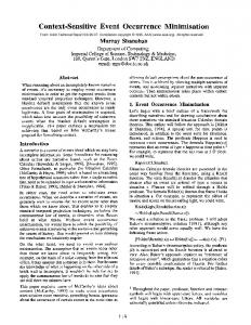
47 During the input transition from ‘0’ to ‘1’, Cl is discharged through the NMOS transistor, and the accumulated energy in Cl is dissipated by this transistor (Rabaey et al., 2003). The expression for dynamic power consumption is widely known:
PD = α ⋅ Cl ⋅ Vdd 2 ⋅ f
(1)
where α is average number of 0 → 1 transitions within oneclock cycle (since the source power is consumed only during the 0 → 1 transitions at the output), and f is the clock frequency. A higher frequency leads to more signal transitions, which in turn, increase the circuit power dissipation. Figure 1
Charging and discharging of a load capacitance (see online version for colours)
2.2 Static power consumption In order to achieve higher density and performance and lower power consumption, CMOS devices have been continuously scaled down for a few decades. However, when the transistor technology has an order of magnitude around or below 100 nm, the advantages gained by the size shrink (increased density and performance as well as power reduction) disappear due to quantum effects which cannot be neglected. These effects produce an excessive increment in the leakage currents. The latter mostly occurs when the transistor is in off state and when it should act as an infinite resistance. Leakage currents consist of two main components: subthreshold leakage current (I2) and gate leakage current (I3) as shown in Figure 2. Figure 2
Leakage current components
2.1 Dynamic power consumption Dynamic power occurs due to the charging of the load capacitance when the transistors change their state from logic ‘0’ to logic ‘1’. For example, consider the inverter circuit in Figure 1. The transistors marked with dot-line are turned off during the corresponding transition. Every time there is a transaction from logic ‘1’ to logic ‘0’ at the inputs of the inverter, the load capacitance Cl is charged from 0 to Vdd. The energy needed for capacitance charging is provided by the power supply Vdd. Additionally, part (half) of the energy provided by the power supply is dissipated on the PMOS transistor.
Source: Roy et al. (2003)
There are some other leakage current components that have started to gain interest recently due to an excessive scaling of the transistor dimensions. They occur due to shorter channel length: injection of hot carriers from substrate to
B. Jovanović and M. Jevtić
gate oxide (I4) and punchthrough leakage (I6), due to thinner oxide thickness: gate-induced drain leakage (I5), and, due to high doping concentrations: junction reverse-biased current (I1) (Roy et al., 2003). However, the largest amount of static power is still owed to subthreshold leakage current. It is the most temperaturedependent leakage component, and thus, every increase in dynamic power produces an exponential increment of the chip temperature, which in turn, increases the leakage component. At 85°C (a common junction temperature limit for commercial hardware), the leakage currents increase by the factor of 60 over their room-temperature values. This leakage components are also one of the main reasons of the scaling process is facing difficulties. Subthreshold leakage current can be expressed as follows: I sub =
μWCox L
VGS − Vth 2 T
V e
ηVT
− VDS ⎛ ⎜1 − e VT ⎜ ⎝
⎞ ⎟ ⎟ ⎠
Figure 3, which plots the short-circuit current through the NMOS transistor during a low-to-high transitions as a function of the load capacitance. Short-circuit current also depends on technological parameters (supply and threshold voltages) as well as the clock frequency. Figure 3
Short-circuit current during transients (see online version for colours) Vdd Vdd -|Vthp| Vin
Vin
Vthn
Vout
Ipeak
isc Cl
t
isc t
(2)
where μ is carrier mobility, W and L channel width and length, respectively, Cox the oxide capacitance, VT the thermal voltage (26 mV at 25°C), η Drain Induced Barrier Lowering (DIBL) coefficient, VGS and VDS voltаges of gate and drain related to the source, respectively, and Vth threshold voltage. Four tunnelling mechanisms (the gate to channel, bulk, source and drain as well as analytical expressions for leakage currents can be found in Roy et al.’s (2003) and Inagaki et al.’s (2007) work.
2.3 Short-circuit power In actual designs, the assumption of the zero rise and fall times of the input wave forms is not correct. The finite slope of the input signal causes a direct current path between Vdd and GND for a short period of time during switching, while the NMOS and the PMOS transistors are conducting simultaneously. From Figure 3 we can see that short-circuit current occurs when the input voltage of CMOS inverter is within a range [Vthn, Vdd – |Vthp|], where Vthn and Vthp are threshold voltages of NMOS and PMOS transistors, respectively. The peak of this current is determined by the saturation current of the device and is hence directly proportional to the sizes of transistors. It is also a strong function of the ratio between input and output slopes, i.e. output capacitance Cl (Rabaey et al., 2003). This relationship is best illustrated by the following simple analysis: consider a CMOS inverter with 0 → 1 at the input. Assume first that the load capacitance is very large, so that the output fall time is significantly larger than the input rise time. Under these circumstances, the input moves through the transient region before output starts to change and the short-circuit current is close to zero. Consider now the reverse case, where the output capacitance is very small, and the output fall time is substantially smaller than the input rise time. The drain-source voltage of the PMOS device equals Vdd for most of the transition period, guaranteeing the maximal short-circuit current (equal to the saturation current of the PMOS). This clearly represents the worst-case condition. The conclusion of the above analysis is shown in
x10 -4
2.5
Cl = 20 fF
2 1.5
isc (A)
48
Cl = 100 fF
1
Cl = 500 fF
0.5 0 -0.5
0
2
time (sec)
4
6 x10⁻¹⁰
Many authors, such as Veendrick (1984) and Bisdounis (2010), were trying to model the energy dissipated due to short-circuit leakage. These models are more or less accurate since they take into consideration more or less parameters and effects which occur in CMOS circuits. Nose and. Sakurai (2000a, 2000b) try to estimate short-circuit power consumption (taking SCEs into consideration) as well as to anticipate its trends in the future generations CMOS circuits. Having in mind continuous scaling trend in transistor supply and threshold voltages, they warn that it is necessary to keep the ratio Vth/Vdd constant. If not, i.e. if the ratio is decreasing (when the threshold voltages scaling at a faster rate than the supply voltage), the effect of the short-circuit power dissipation will increase and become an important part (up to 20%) of the total power dissipation of CMOS VLSIs. One of the most efficient techniques for optimising short-circuit power consumption in a global way is the technique of matching (equalising) the rise/fall times of the input and output signals. At the overall circuit level, this means that rise/fall times of all signals should be kept constant within a range. In this way, most power dissipation is associated with the static and dynamic power. Only a minor fraction (0 and R0 < 0 then Rem := R0 + D; Q := Q − 1; elseif X 0 then Rem:= R0 −D; Q := Q+1; else Rem := R0; endif; label: if Y