the transfer function for a cavitating inducer and shows that the numerical ..... An axial inducer designed to operate with cavitation is a com- ..... Saturn Engines.
Reprinted from June 1976, Vol. 98, Journal of Fluids Engineering
mic Transfer Function for a C. BRENNEN
California Institute of Technology, Pasadena, Calif.
Knowledge of the dynamic performance of p u m p s is essential for the prediction of transient behavior and instabilities in hydraulic systems; the necessary information i s in the form of a transfer function which relates the instantaneous or fluctuating pressure and mass flow rate at inlet to the same quantities in the discharge from the p u m p . T h e presence of cavitation within the p u m p can have a major e$ect o n this transjer function since dynamical changes in the volume of cavitation contribute to the diflerence in the instantaneous inlet and discharge mass flow rates. T h e preselzt paper utilizes results from free streamline cascade theory to evaluate the elements in the transfer function for a cavitating inducer and shows that the numerical results are consistent with the characteristics observed in some dynamic tests o n rocket engine turbopumps.
Introduction The development in lecent times of hiqh speed and high performance pumps for hquids and their inclucion in increasingly complex hydraulic systems has created a need for improvement in our unde:standing of these fl2ws. Demands cf space and economy almost invariably lead to pump (or turbine) designs which operate either with cavitation or sufficiently close to that point, so that significant perturbations lead to cavitation. Sometimes the demands of pump size or mass are exceedingly stringent a s in rocket engines (or propulsion devices of other high performance vehicleb) so that :he pumps operate with extensive cavitation at the inlet. In other situations high temperatmes and velocities plus the need to economize on highly expensive equipment draw the designer ever closer if not beyond the point of cavitation inception; such appears to be the case in the boiler feed a ~ coolant d systems not only of conventional but also of ~mcleargenerating plants. Another situation occurs in systems such a,. those associated wit,h geothermal generating plants where flashing of two phases can lead to cavitation-like phenomena in the pumps and turbine.. With regard to turb:nes one should remember that cavitation phenomena similar to those at pump inlet a l ~ ooccur on the outlet side of turbines where there exists an analogous set of conditions; though we will speak here only of pumps the complenlcntary problem in turbines should be borne in mind.
Contributed by the Fluids Engineering Division of THEAMERICAN SOCIETY MECHANICAL ENGINEERB and presented at the Winter Annual Meeting. Houston, Texas, November 30-December 4, 1975. Manvscript received at ASME Headquarters August 15, 1975. Paper No. 75-WA/FE-16.
Major problems remain in connection with the steady-stat operation of such cavitating pumps and turbines. The prediction of the advent of cavitation, the form it takes, its effect upon performance and the material damage i t can cause are stil! subjects of intensive research. But i t is rapidly becoming apparent that a whole new tet of t,echnological problems are arising w F c h involve the dynamic rather than the steady state operation of such turbomachines. Formerly i t was sufficient for the designer to analyze the steadv-state operation of a hydraulic system. With the increasing complexity dynamic and stability analyses are now desirable for pumping sy~temaand are required for hydropower inftallations [I, 21.1 Transient problems also occur in boiler feed systems [3, 41 and the resonances of fully wetted hydraultc systems have received recent attention 151. When a second phase makes its appearance analysis of these systems becomes considerably more complex. The fluid may theu be consideled as a m~xture(e.g., [6]) or the liquid column may be assumed to divide into distinct parts ~eparatedby vapor [7, $]. These studies have concentrated attention almost entirely on the unst,eady flow within the pipeline components of hydraulic systems even though it is known that any associated fluid machine participates in the unsteady motion. The first step in providing n fuller knowledge of the complete performance characteristics of a pump or turbine was probably taken by Knapp [9]. The now well-known circle diagram provides the steady-state behavior for all combinations of flow (quantity and direction) and rotative speed (including sense). The unsteady tests carried out by Knapp to verify the use of the complete characterisbic
OF
--
INurnbers in brackets designate References at end of paper.
Transactions of th
were done a t such a low frequency that the steady behavior was entirely sufficient. In modern applications however the. f r e quency of the unsteady-perturbations may get quite high. Although the dynamic effect associated with any disturbance frequency can only be evaluated properly as a dimensiodess reduced frequency, it seems reasonable that there should be a modification of the basic steady-state characteristics for higher frequencies. Yet one of the stumbling blocks for the dynamic analysis of these modern applications is often the almost total iack of knowledge of the dynamic behavior of a pump or turbine, particu!ar!y when there i~ cavitation present I t may be expected that a full understanding of these relations would at the very least be exceedingly complev. Fortunately for many if not most hydraulic systern response antllysrs it is sufficient to deal with small departures from some average state of operation. These small departures are then usually assumed to be elated by linear equations. Thus it becomes possible t80relate fluctuating inlet quantities to corresponding outlet ones by means of linear equations of the form (for constant rotative speed)
In this equation F1, Gil refer to the fluctuating inlet pressure and mass flow rate and $2, 62 to the corresponding discharge quantities. The matrix [Zj is called the transfer matrix. Generally the coefficients may be expected to depend on frequency, the operating point and degree of cavitation. For very low frequencies equation (1) shuuld reduce to the usual steady state operating characteristics of a flow machine. In this limit we can identify Zll as the slope of the pressure-rise versus inlet pressure curve at constant speed; this is the familiar cavitation performance curve. Furthermore, 2 1 2 can then be interpreted as the slope of the pressure rise-mass flow curve; that is, it is just the slope of the "H-Q" curve at that paiticular operating point. Cavitation plays a major role in th% transfer function since oscillation
a
nondimensional cross-sectional cavity area, A*/h" A" = cross-sectional cavity area A i = inducer inlet area A, R = complex constants C, CB, C2 = dimensional compliances d(r) = ratio of blade thickness to normal blade spacing at radius, r G = pump gain h(r) = leading edge spacing a t radius, r H = leading edge spacing a t tip, h(R) i = spacewise imaginery unit j = timewise imaginery unit K L = local nondimensional compliance K B = overall nondimensional compliance L = fluid inertance h = nondiinensional oscillatory mass flow rate, ?%*/pAiUT m* = oscillatory mass flow rate d l ~= local mass flow gain factor (nondimensional) M B = overall mass flow gain factor (nondirnensional) =
Journal of Fluids Engineering
in the volume of cavitation is often the only significant source for the difference between the instantaneous inlet and discharge rnass flows. Indeed if liquid compressibility and structural complia,nce were negligible 2 2 1 aad 2 2 2 would be zero in the absence of cavitation and the dynamic charactenstics would then be much simpler. In the presence of cavitation we are faced with the problem of evaluating the four complex or eight real elements of [Z] (the variables gl, 232, ml and 6% being complex in order to incorporate both their amplitude and their phase relationships) a s functions not only of frequency, 0,but also of the steady-state operating conditions, including the cavitation number cr, which characterizes the extent of cavitation in the pump. Furthermore, it should be noted that [Z] as defined in equation (1) is probably the minimum information required; the size of the matrix could be further increased by the incorporation of other independent fluctuating quantities w~chas rotational speed of the pump impeller. In some turbomachinery applications such fluctuations in the rotational speed may be a relatively passive effect, that is to say a response to the fluctuating loads on the impeller blades. In other situations such as in rocket engines the pump may be driven by a turbine powered by fluid bled from the throughflow so that additional dynamic interactions are present. In either case the matrix elements which characterize this situation would clearly include properties of the mechanical drive train and its prime mover. Some considerations of the effects of rotational speed fluctuations will be included in Appendix I. The purpose of the presznt work is to outline a procedure to evaluate the elements of the transfer matrix for low frequencies. This may be regarded as a first step to extend the pump characteristics into the region of unsteady operation. The basic means of analysis for this work is quasi-steady free-streamline C----A.G theory. In what follows the relation between this type of cavitation and what is observed is compared for some representative pump impellers. The terms of the transfer function can then bc evaluated and compared in the limit of low frequency with current lumped parameter models of cavitating pumps.
Ma* = a dimensional mass flow gain factor ?I = number of inducer blades N = fluctuating rotational speed of inducer Nr. = local rotational influence factor NB = overall rotational influence factor p* = pressure pc = cavity pressure @* = oscillatory pressure j3 = nondimensional oscillatory pressure r = radial coordinate in the inducer R = radius of inducer tip RII = radius of inducer hub R1, Rt = fluid resistances Rp = pump resistance .. RD = discharge resistance u, v , = fluid velocities in x, y directions U F = axial fluid velocitv a t inducer inlet UB(T) = blade velocity a t radius, r UT = inducer tip speed, UB(R) Ul(r) = fluid velocity relative to
V
= w = x, y =
z = =
Z
a(r) = P(r) = ( = p
-
a ~ ( r )= UT
=
q =
o =
8
=
blades a t radius, r total cavity volume complex velocity, u - i v cartesian coordinates in cascade plane x+iy transfer matrix and its elements angle of attack a t radius, r blade angle a t radius, r * complex variable in transformed plane liquid density local cavitation number a t radius, T overall or tip cavitation number, c r ~ f R ) flow coefficient, UF/UT nondimensional fluctuation frequency, QH/UT fluctuation frequency
Subscripts
1 = conditions a t inducer inlet 2 = conditions a t inducer dis-
charge J U N E 1976
/ 183
A new factor is seen to be required which appears to remove much of the discrepancy between theoretically derived transfer function elements and those deduced from flight and field test,s.
Background Before proceeding it is worth describing a specific example of a pump application problem in which knowledge of the transfer function is essential. Virtually all liquid-propelled rockets are susceptible to an instability which involves a closed loop interaction between the 1ong;tud;nal structural modes of vibration of the vehicle and the dynamics of the propulsion system [lo, 111 This FO-called"POGO" instability is an extreme hazard since it can lead to excessive accelerations of the payload, stresses on the structure and possible premature shutdown. Simplistically described, the instability involves longitudinal structurttl vibrations which lead to pressure fluctuations in the fuel and oxidizer tanks, and to pressure and mass flow oscil!ations in the feedlines. The cavitating propellant pumps thus experience fluctuating inlet conditions and as a result the engines can produce an oscillating thrust which can lead to further amplification of the longitudinal structural vibration. Most of the essential elements in this system are well understood and quantifiable dynamically with the notable and important exception of the turbopumps. We cite this particular example because it is one of the few situations in which detailed attempts have been made to analyze and measure the dynamic characteristics of cavitating turbomachine8. Quantitative details are not readily avaiable for commercial and utility applications often for proprietary and legal reasons (hence the paucity of reference here). Informal reports of disastrous resonances involving cavitation in the suction lines and pumps of boiler feed systems do persist however. Sometimes such problems are manifest during transient operation [3, 41: in other situations cavitation-induced resonances may occur. The latter have been the subject of recent studies by Sack Nottage [12] and Natanzon, et al. [13] which are in the same spirit as the present paper.
Transfer Matrix, Frequency Dependence
a,
Fortunately in many practical situations the frequencies, are sufficiently small to suggest reasonable validity for solution of the ma.tlix elements in series with ascending powers of Q. We have previously indicated [14] that the reduced frequencies involved in the POGO instability are often small enough for such a procedure. Thus, in the present paper we shall focus attention on the first nonzero tern1 in the series for each element in [Z]. The zeroth order or frequency independent terms in Zll and 2 1 2 should as previously discussed then be given by the steady-state operating characteristics of the pump (see, for exarnple, Wagner [15]); the former by the slope of the steady state curve of pressure rise against inlet pressure and the latter by the slope of the
pressure rise versus flow rate for a given inlet pressure. Therefore we shall concentrate here on the terms Zzl and 2 2 2 which must begin wit'h term3 linear in frequency since the mass flow difference is zero in steady-state operation. However, we shall see that values for 2 2 1 and 2 2 2 can be deduced from knowledge of a series of quasi-static or steady cavitating flows through an inducer. On the other hand, in order to obtain the second terms in each of the elements i t is necessary to solve the difficult fundamental problem of truly unsteady flow in a cavitating pump. Though the !atter task is becoming feasible for an axial inducer through the work of Kim and Acosta [16] and Furuya [17], the present paper will concentrate on the evaluat.ion of the first terms in 2 2 1 and 2 2 2 . These elements relate the instantaneous difference between the inlet and outlet mass fiows to the inlet fluctuating conditions
where 131, 132, &I, 6 2 denote dimensionless fluctuating pressures and mass flows a t inlet and discharge (for definition see equations [S]). In dynamic operation the mass flow difference is, of course, caused by the growth or shrinkage of the total volume of cavitation within the pump. Thus 2 2 1 and Znn are directly linked with cavitation and the purpose here will be to develop and construct this relationship. Up t o the present time dynamicists concerned, for example, with analysis of the POGO instability (e.g.,-Rubin [ll], Rubin, Wagner and Payne 1181) have been required to make some dynamic model of a cavitating turbopump and have thus resorted to some rather arbitrary assumptions. Until recently it was conventional, for example, to assume that all of the cavitation could be lumped into a single bubble a t the inlet side of the pump and to assume that this bubble had a simple spring-constant response to the fluctuating pressure a t inlet. This response was termed the cavitation compliance of the inducer and is related to some value for 221. More recently data on this cavitation compliance has been collected by Ghahrsmani and Rubin 1191, Brennen and Acosta [14] and Brennen [20] with the intent of relating that, quantity to the extent and type of cavitation expected. Furt,her, it seems to have been universally assumed for lack of any other knowledge that 2 2 2 was identically zero. A particular purpose of this paper is to demonstrate that according to the present calculations for typical inducers 2 2 2 is far from xero and may indeed represent a major dynamic effect. Since cavitation in an inducer can take a number of forms (see Brennen [20] for example) it has proved convenient to separately investigate the dynamic3 of each form. The compliance of fully developed blade cavities was investigated by Brennen and Acosta [I41 and that of bubble cavitation by Brennen [20], I n the latter it was shown that bubble cavitation is capable of contributing substantially to the compliance in the
r CAVITY
I:,. am
INLET AXIAL VELOCITY, U,
~ N D U C E RINLET AREA. NUMBER OF BLADES, Z
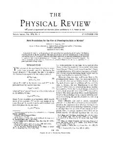
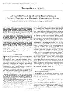
Fig. 1 inducer inlet with nomenclature
184 /
J U N E 1976
Transactions of the ASME
absence of blade cavitation. But when blade cavitation occurs, the preseure in the fluid exterior to the blade cavity is generally zbsve the vapor pressure and hence there is little bubble cavitation, except in the tip clearance a.nd backflow regions. Neglecting these other features, it would seem plausible to argue that when cavitation is sufficiently extensive for blade cavities to be formed the latter would contribute a major part of the compliance. Yet the theoretically calculated blade cavitation compliances of Brennen and Acosta [14] are generally much srualler than those deduced from experimental observation by Vaage, Fidler and Zehn!e 911. The present paper addresses itself to this discrepancy and demonstrates that its cause probably lies in the hypothctical dynamic model which is employed in order to deduce the conipliance from the experimental measurements, I t is demonstrated that for most of the cavitation number range, the fttctor Zrz is as important as 2 2 1 in determining the dynan4c effect of the cavitation and that the calculated valnes of Z2t are in fair agreement with the dynamic effect deduced from tests Finally we should mention that Kolesnikov and Kinelev (321 have presented a theoretical analysis of the dynamic behavior of cavitating pumps by considering the entire flow between blade^ to consist of a !iquid/bubble mixture; they proceed to evaluate the dynamic effects associated with this mixime and the much reduced sonic velocity they ascribe to it. No quantitative data is presented and apart from the overly simplistic view of cavitation and the b a ~ i cmixture as~umptions,other empirical relations a~71umedmake it difficult to aqsess the value of their an slysis.
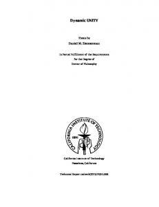
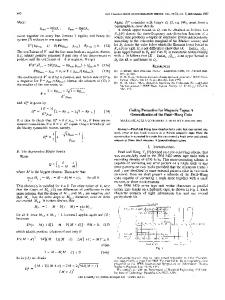
Axial Inducer Cascade Solutions An axial inducer designed to operate with cavitation is a common feature of high performance pumps and it is to this cornponent, the principle source of cavitation in a pump that present &Tort is directed. The flow in an inducer is exceedingly complex (noncavitating inducer flows have been extensively treated recently by Lakshminarayana [27]) and it is necessary to make rather crude assumptions in order to construct even approximate flow solutions. Frequently it is assumed that the radial velocity components in the inducer can be neglected so that each radial station can then be unrolled into a cascade as indicated in Fig. 1. Free streamline potential flow models of these annular cascades have been employed extensively in the past to study steady cavitating flow in turbomachines. Most of the flow solutions have been based on a linearized approach, (Cohen and Sutherland [22], Acosta and Hollander [23], Acosta [24], Wade [25]), although Stripling and Acosta [26] have also considered the more exact nonlinear cavitating cascade problem. Unfortunately all of these methods are ~ignificant~ly deficient in that they assume infinitely thin blades and thus neglect the often critical effects of blade thickness. Brennen and Acosta 1141 attempted to rectify this in presenting a simple linearized solution which includes finite blade thickness. The cascade in the x = x iy-plane is first conformally mapped into the {-plane of Fig. 2 by
+
The linearized free streamline solution of this problem for infinitely thin blades was first given by Acosta and Hollander i231 and consists of the first three terms an the right hand side of eq1-lation (3) for the complex velocity, w = u - iv (u,c are velocity components in X, directioils). Brennen and Acosta 1141 added the fourth term and showed that this rapresented a silnple solllhn for the case of blades with the ultimat,e thickness dh cos P
-
BLADE
BLADE SUCTION SURFACE
&I'
Fig. 2 Transformed 6-plane for linearized solution of flow in cavitating cascade
The cavitation number, UL, is defined in the conventional way as (pl* - pC)/112pU12where pl*, pc are the upstream and cavity pressures, U1 is the inlet fluid velocity relative to the blades and p the liquid density. The complex constants A, B are then obtained from the conditions at upstream and downstream infinity and a continuity condition (which involves d). Fina!ly the solu, be written in terms, tion (3) and the cavitation number, a ~can of d, a, p, h, U1 and a convenient parameter, I, representing the length of the cavity in the transformed plane. Ordinates describing the shape of the foil profile and the cavity profile are then obtained and integration leads to a cavity area, A*. or volume per unit depth of the plane flow. The dimensionless volume a = A*/h2 is then a function of the values of a , P, d and UL relevant to the particular cascade under consideration. Note that P(r), d(r) are fixed geometric functions of radial position, r, but that a ( r ) will vary with the flow coefficient, cp defined as U p / U ~(where the fluid velocity, UF, is assumed independent of r) according to a(r)
'IT
= 2
Rv - @(r)- tan+ r
where R is the radius of the inducer tip (velocity UT). Furthermore the local value of a~ will differ from the overall or tip cavitation number for the inducer, UT as given by the relation UT =
(pi*
1
- PC)/ i p(Ufl -k
Ua2)
(5)
where pl* is the inlet pressure. However, since UF is usually small compared with UT it follows that
and hence the radial function a ~ ( ris) readily determined The total volume of cavity in the inducer, V, which is a function of the inducer operating conditions, cp, UT, can then be written as
where N is the number of blades (h(r) = 27rr/N) and RH i; the radius of the hub The basic quantities a, d a / a ~and ~ da/da required in the following analysis (as functions of a , 6, d, UL) were computed in a subroutine by methods similar to those used [14]'
Quasistatic Analyses; Cavitation Compliance We shall now relate the instantaneous lnass flow rate difference (fil - &2) to the rate of change of the cavity volume V with the objective of evaluating ZZl and h2fmm equation (7). that the most convenient manner in which It will become to nondimensionalize the fluctuating pressures and mass flow rates and their frequency, Q, is as follows:
where stars denote the correspondlng dimensional quantities, Ai, is the inducer inlet area and w is the reduced frequency, Let us consider first the term 221; since this parameter is obtained with %I = 0 i t follows that only UT, UL and not cp or a vary throughout a cycle of the fluctuations. The resulting cyclic change in the volume of the cavity is thus caused by fluctuations in the cavitation number alone. T h l ~ sfollowing a quasistatic approach we may connect the cavity volume variation with the mass flow rate difference through the relation
where j is the imaginary index. Then substituting for V from equation (7), taking the derivative inside the integral and making use of the approximate relation d/dpl = ( r 2 U ~ 2 / R 2 ) d / dthe a~ resulting expression for 2 2 1 is most conveniently written as
the mass flow gain factor (cf., equation (10))
Substituting into equation (13) for V from the relation (7) one obtains
in which the local mass flow gain factor, ML, defined in equation (15) is given by da ML(g, a r , r/R) = U B- . ~ U F
where Kg is termed the dimensiontess cavitation compliance of the pump and is given by
For a particular radius, variation in the inlet velocity, UF, will cause variation in the area, a, by changing the angle of attack, a, and to a lesser extent by changing the local cavitation number, UL;thus
where K L is a local compliance being given by
Because the inlet pressure is now held constant i t follows tha.t
Values of KL arc immediately available from the cascade solution once a , p, d and UL have been determined . Note that the choice of non-dimensional variables in equation (8) has resulted in the most convenient expressions for 2 2 1 , Kg and KL. Also note that the definition (11) has been arranged, so that if K L incieases linearly with r within the inducer, then the value of KB is equal to the value of the local compliance K L a t the tip; frequently this is not a bad first approximation. Finally, it should be noted that the dimensionless compliance, Kg, is closely related through HA the ~ dimensional cavitation the expression KB = C B U ~ ' ~ / ~ to conlpliance, CB, used by Ghahremani and Rubin [19], and others in connection with rocket t,urbopumps. The above method for calculating a pump compliance, Kg, is essentially that employed previously by Brennen and Acosta [14]. The resulting theoretical values of KB were found to be: between three and ten times smaller than values derived from experiments on the F1, H1 and 52 Saturn engine turbopumps. As shown in the next section this is due to neglect of the term 2 2 2 which we call the Mass Flow Gain Factor.
since cot ( a
Mass Flow Gain Factor Methods analogous to those of the previous section allow calculation of 2 2 2 as well as 2 2 1 (or KB). By definition the compliance, Ka arises from the response of the cavity volume to fluctuations in the inlet pressure (or more specifically the cavitation number) while the inlet flow rate or flow coefficient remains constant. On the other hand, the quantity 2 2 2 results from variations in thc cavity volume because of fluctuations in the flow coefficient or angle of attack due to fluctuating inlet flow rate while the inlst pressure remains constant. Thus the evaluation of 2 2 2 proceeds along lines similar to that of the last section except that the inlet pressure is maintained constant while the inlet flow rate varies. I t follows from the definition (2) that
By analogy with the compliance derivation it is clear that we should define a dimensionless quantity, MB, which we will tern1
+ p)
ML((o,QT,r/R)
=
=
UF/UB. Finally ML becomes
sin ( a
+ P)
2 a cos ~ (a
+ p)
da aaL
Thus in order to evaluate the loca,l mass flow gain factor and, by integration, the overall mass flow gain factor we need only evaluate the quantities da/da! from the cascade analysis (in addition to the quantities d a / d a ~used in evaluating the compliance) It is worth anticipating the numerical results to note that the term in ML involving d a / d a ~is generally much smaller than the da/da term. This is merely a reflection of the fact that a /3 is generally close to 7r/2 so that
+
The parallel development of the compliance and mass flow gain factor permits us to write the following simple relation which is obtained by differentiation from equations (12), (20), (11), (15) and (4):
That is to say the rate of change of the mass flow gain factor (P must be approximately equal to the rate with U T for co~~stant of change compliance with flow coefficient for constant aT. This relation can be most useful in interpreting the results for mass flow gain factor and conlpliance.
Some Examples I n order to present examples of compliances and mass flow gain factors the following turbopump inducer designs were selected : A
Impeller 111.
A simple inducer
=
81') whose blades
Transactions of the ASME
IMPELLER
E !
LPOTS
0.005
0.003L0!3
0!4
015
016
017
0!8
0!9
l!O
I
TIP RADIAL
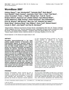
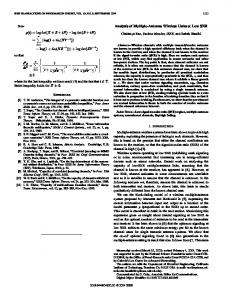
R A D I A L P O S I T I O N , r/R Fig. 3 Radial variatiorts of the blade angle 8, blade thickness to nor ma1 spacing ratio, d, and angle of attack, a, (for various flow coeffi cients, (P) for the simple helical inducer of Impeller 111
lie along helical surfaces (similar to those employed in the cavitation studies of Acosta [ZS]). The hub ratio is 0.4 and the distributions of P, d and a (for various cp) are indicated in Fig. 3.
0.5-',
.
1
1
1
. .. .
IMPELLER
\
0.4 -
I
I
I
E l LPOTS
a($=0.12)
HUB
I
I
1
0.4
0 5
06
I 0.7
I
0 8
R A D I A L POSITION , r / R
I
0.9
1
r/R
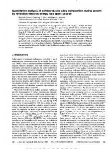
B impeller IV LPOTS. This is the projected design for the inducer of the low pressure oxidizer pump to be used in the main engine of the Shuttle space vehicle. The radial distributions of p, d arid a are indicated in Fig. 4. A primary reason for the choice of this impeller is the projection that this inducer will be important from the point of view of possible POGO instabilj ties. The high pressure oxidizer pump will also be important but will be less susceptible t o cavitation; in the light of past experience, the fuel pumps are unlikely to be a major factor. As described in detail by Brennen and Acosta 1141 an important byproduct of the cascade analysis is the value of the tip cavitation number, UT, a t which the flow a t a particular radial station becomes choked. These values are shown in Fig. 5 and suggest that the breakdown cavitation number for the Impeller 111 will be close to 0.009 while that for the LPOTS inducer will be in the neighborhood of 0.011. The difference is primarily due to the fact that the blades of the LPOTS inducer are much thicker near the hub. Fig. 5 suggests choking will first occur near the hub of the LPOTS inducer as UT is reduced. Examples of the radial distributions of compliance, KL, and mass flow gain factor, ML, are given in Figs. 6 and 7. From these we may anticipate that the overall mass flow gain factor will decrease much less rapidly than compliance as the cavitation number is raised. Integrated compliances, KB, and mass flow gain factors, ME, for the inducers are presented in Figs. 8 and 9. Perhaps the most significant feature of these results is that, over most of the range of cavitation number, the mass flow gain factor, MB, is very much larger than the compliance, Kg. This strongly suggests that any dynamic model for the transfer function, [Z], which omits Z22or MB while retaining Kg could be significantly in error. In order to illustrate this it is necessary to delve more deeply into the models used by the dynamicists to extract compliance values from experimental observations.
1
1'IP
Fig. 4 Radial variations of the blade angle 8, blade thickness to norm a l spacing ratio, d, and angle of attack, a, (for various flow coefficients, co) for the IQWpressure oxidizer turbopurnp of the main shuttle engine (designated Impeller LPOTS).
Journal of Fluids Engineering
POSITION,
Fig. 5 The tip cavitation numbers a t which the flow a t each radial station becomes choked; values for both impellers and for various flow coefficients, P
Some Comparison With Test Observations of Saturn Engines Since computed compliances, Kg, for the oxidizer (-0) and
I
I
IMPELLER
m
HUB
I
for
I
I
4=0.06
RADIAL POSITION
,
TIP
r/R
Fig. 6 Example of the radial distributions of compliance, KL, and mass flow gain factor, ML, for Impeller I l l a t a flow coefficient of 0.06 and various tip cavitation numbers, UT
fuel ( - F ) turbopumps of the Saturn engines (52, F1, H I ) were compared with values deduced from experimental test observations (Vaage, Fidler and Zehnle [21])in the earlier paper of Brennen and L o s t a [14] it is appropriate that we should introduce calculated values of the mass flow gain factor into this picture and investigate whether the experimental observations can be explained in terms of this additional parameter. Since extensive tests were performed on t-he J2-0 turbopump, we select this for particular study. Fig. 10 presents the computed results for the compliance, Kg, and mass flow gain factor, MB, of the 52-0 turbopump near the design flow coefficient (9= 0.097) based on the radial distributions of blade angle and blade thickness included in Brennen and Acosta [14]. The circled points represent the values for the nondimensional compliance deduced from engine tests in the Rocketdyne facility (see below) and the difference between these experimental values (obtained by assuming Zzz= 0) and the theoretical Kg is clearly evident. This discrepancy would appear to be even greater for other Saturn turbopumps (Brennen and Acosta [14]) Lumped paramekr electrical analogies have been employed to model the presumed dynamical behavior of rocket turbopumps; from these, experimental compliance values are deduced. The simplest model employed for example by Murphy (1969) visualizes the pump as consisting of a compliance element, C, a pressure (voltage) amplifier of gain, G, and a pump resistance, Rp as in Model A, Fig. 11. The discharge line is conventionally represented by an inertance, L, and a discharge resistance, Rn. However in the tests under consideration RDwas estimated to be small compared with Rr (Murphy [29] and private communication) so that for simplicity it is convenient to assume that it is absorbed in Rp and that the load merely consists of the inertance, L. I n general the experimental observations which consist of pressure fluctuation measurements for inlet perturbations over a range of frequencies, Q, are analyzed in the followjng way. First theoretical estimates are made for some of the quantities such as L, Rp and G, the last being close to unity (e.g.,
_I
z LZ
P
0.9
I I I I IMPELLER IE LPOTS for $ = 0.06
Z
I
I
t
HUB
R A D I A L POSITION , r / R
Fig. 7 Example of the radial distributions of compliance, KL, and mass flow gain factor, ML, for Impeller IV LPOTS at a flow coefficient of 0.06 and various tip cavitation numbers, UT.
188 /
J U N E 1976
TIP CAVITATION
NUMBER,
UT
Fig. 8 Calculated compliance, Kg, and mass flow gain factor, MB, for Impeller III as a function of flow coefficient, P, and tip cavitation number, UT
Transactions of the ASME
TIP CAVITATION
NUMBER , uT
Fig. 9 Calculated compliance, Kg, and mass flow gain factor, MB, for low pressure oxidizer turbopump i n the main shuttle engine (Impeller IV LPOTS) as a function of flow coefficient and t i p cavitation number, aT
1
I
I
I
I
I
0.02
0.03
0.04
0-05
0.06
TIP
-------
tion. The analysis cannot predict variations in Mg* and CBwhen w is no longer small. Therefore if the expressions (22) snd (23)
L
DISCHARGE
DISCHARGE
COMPLIANCE MODEL
B
A
p; = ~i;: - R~G; DISCHARGE
INLET
MASS FLOW ,GAIN
Journal of Fluids Engineering
8
PUMP
"DOUBLE
Now in comparing (22) and (23) it is well to remember the limitations of our quasistatic analysis and therefore t.he transfer func-
......
......
INLET
Now consider Model C which we might construct from the considerations of this paper. I t consists of a pump transfer function containing a gain, G, a pump resistance, RP, the dimensional mass flow gain factor, Mn*, and the dimensional compliance, CB. The input impedance is thus
(
NUMBER, uT
Fig. 10 Dynamic characteristics of the J2-0 turbopump. Theoretically , and mass flow gain factor, calculated compliance, Kg, , for cp = 0.097. Values derived f r o m experimental obMg-servation: (1) main compliance, C,derived from double compliance 0; (2) compliance, Kg, 0 and Model B, 0 A, from Model C of this mass flow gain factor, Mg. A paper
.....
Murphy [29] used 1.2). Then the observations are analyzed to find the values of the compliance, C, a t various cavitation numhers or suction pressures, which yield the best fit to the input impedance of the electrical analogy. The most detailed investigation of this type was that pelfornied on the 52-0 turbopump (references [21, 30, 311). I t was apparent from the results of those investigations that a single mriable, (I, was insufficient to properly match the observations. As a result a particular empirical model was proposed which seemed to fit the data quite well. This so-called "double compliance model" is shown as Model B in Fig. 11 and values for C, Rl/G, R2/G, GC2 and L/G are given by Vaage, FidIer and Zehnle [21]. Dimensional values for C and RJG are also listed in t,he first part of Table 1 and it is the nondimensional version of C which is plotted in Fig. 10. The input impedance of Model B is
CAVITATION
FACTOR
MODEL
C
Fig. 11 Electronic analogies for the dynamic behavior of cavitating turbopumps and the mass flow gain factor Model C of this paper
are equated and the result arranged as a polynomial .in jQ we are only justified in eqnating the coefficients of first two terms in the polynominal, a t most. The first coefficient obviouslv yields Rp = R1; the second coefficient gives
Thus dynamic behavior equivalent to that of the Double Con~plianceModel can bc constructed from a mass flow gain factor, MB*, and a compliance, CB, which are related through equation (24) to the values for C and R I / G yiven in Table 1. This simple analysis cannot separate CB and MB* but a set of dimensional values consistent with the experiinental data [30, 31 and 211 are listed in Table 1 and plotted nondimensionally in Fig. 10. Comparing these with the theoretical values of K B and i l f ~i t is clear that there iq significantly better agreement t h a ~ , between the Double Compliance Model compliance alone and the theoretical Kn. Indeed, given t,he approximate nature of the experimental data the agreement is most encouraging. Furthermore, it should be noted that the somewhat greater experimental colnpliance and mass flow gain factor could arise through cont,ributions from tip vortex, backflow and bubble cavitation volumes which are not, of course, included in the present theory.
are e~periment~al indications of significant differences between static and dynamic pump gains [15]. Such effects would have to be included in Model C, Fig. 11 and would influence the values of compliance and mass flow gain factor derived from the experimental observations. Clearly, however, there is a dire need for more specific and detailed experimental data on the complete transfer function. Such experi&nts, unlike the previous tests, should measure directly the fluctuating pressures and mass flow rates a t inlet and discharge and thus permit conclusive comparison between theory and experiment. We are presently involved in such an experiment and hope to present such results in the near future.
Acknowledgment The authors are indebted to the George Marshall Space Flight Center, Huntsville, Alabama for support under NASA Contract NAS 8-28046 and to Mr. L. Gross of NASA, Huntsville, Dr. S. Rubin of Aerospace Corporation and Dr. J. Fenwick of the Rocketdyne Division of Rockwell International for valuable suggestions and advice.
References
1 Jaeger, C., "The Theory of Resonance in Hydro-Power Systems, Discussion of Incidents and Accidents Occurring in Pressure Svstems." Journal of Basic Engineering, - . Vol. 85, 1963, pp. 631-64b. 2 Streeter, V. L., and Wylie, E. B., "Waterhammer and Tip Surge Control, Annual Review of Fluid Mechanics, Vol. 6, 1974, cavitation Double compliance Mass flow gain(.) pp. 57-73. number Model B factor model C 3 Liao, G. S., "Protection of Boiler Feed Pump Against Transient Suction Decay," Journal of Engineering for Power, Vol. 96, 1974, pp. 247-255. 4 Liao, G. S., and Leung, P., "Analysis of Feedwater Pump Suction Pressure Decay Under Instant Turbine Load Rejection," Journal of Engineering for Power, Vol. 34, 1972, pfi. 83-90. 5 Zielke, W., and Hack, H. P., "Resonance Frequencies and Associated Mode Shapes of Pressurized Piping Systems," lnternational Conference Pressure Surges, Paper G-1, Brit,. Hydromech. Ites. Assoc., Cranfield, England, GI-1-13, 1972. 6 Wijngaarden, L. van, "On the Equations of Motion for Mixtures of Liauid and Gas Bubbles," Journal of Fluid ~Mechan(u)For the 52-0 pump the nondinlensional Kg is given by ics, Vol. 33, 1968, p. 465. C B / ( ~.48 X 10-5 m2) and the nondimensional MB by i l f R 4 X 7 Weyler, M. E., Streeter, V. L., and Larsen, P. S., "An (279s-l ) Investigation of the Effect of Cavitation Bubbles on the Momentum Loss in Transient Pipe Flow," Journal of Fluids Engineering, Vol. 93, 1971, pp. 1-10. 8 Safwat, H. H., and Van Den Polder, J., "Experimental Concluding Remarks and Analytical Data Correlation Study of Water Column SepIt has been demonstrated that, a transfer function which in- aration," Journal of Fluids Engineering, TRANS.ASME, Vol. 9.5, cludes not only a compliance element but also a mass flow g a i ~ 1973, pp. 91-97. It. T., "Complete Characteristics of Centrifugal factor is a satisfactory first approximation for a cavitating pump. P u 9m ~Knapp, sand Their Use in the Predictmionof Transient Behavior," I n the past, neglect of this latter factor led to large discrepancies ~ i t . 1 6 ASME, ~. Nov. 1937, pp. 683-689. between compliances estimated theoretically on the basis of free 10 Prevention of coupled-structure propulsion instability (POGO), NASA SP-8055, Oct. 1970. streamline solutians of the fully cavitating cascade flow through 11 Rubin, S., "Longitudinal Instab,i,lity of Liquid Rocket,s a n inducer and "co:npliances" evaluated from experimental obdue to Propulsion Feedback (POGO), Journal of Spacecraft servation of the dynamic behavior of cavitating pumps. When and Rockets, Vol. 3, No. 8, 1966, pp. 1188-1195. the latter are a~lalyzedwith prior knowledge of the existence of a 12 Sack, L. E., and Nottage, 13. B., "System ~scilldtions Associated With Cavitating Inducers," Journal of Basic Engineermass flow gain factor when the differences between the theory 87, Series D, No. 4, 1965, pp. 917-925. and experi~nentalobservations are very much smaller and the ing, Vol. 13 Natanzon, 31. S., Bal'tsev, N. I., Bazhanov, V. V., and conlparison provides support for the validity of the theoretical Leydervarger, 11. R., "Experimental Investigations of Cavitamodel. The experimental values of compliance and mass flow tation-Induced Oscillations of Helical Inducers," Fluid Mechangain factor still appear to be somewhat higher than the theo- ics Soviet Research, Vol. 3, 1974, pp. 38-45;( 14 Brennen; C., and Acosta, A. J., Theoretical, Quasiretical values. Since the theory of the preseut paper considem Static Analysis of Cavitatiorl Compliance in Turbopumps," only fully developed blade cavities and neglects the volume of ti;) Journal of Spacecraft and Rockets, Vol. 10, NO. 3, 1973, pp. vortex, backflow and bubble cavities it would seem reasonable to 175-180. 15 Wagner, It. G., "Tit,an I1 Engine Transfer Function Test associate this !atter volunle with the remaining discrepancy. Results. Reuort No. TOR-0059 (6471)-9, Aerospace CorporaHowever there are also limitations to the present theory which ' Calif ., Feb. 1971. tion, ~ 1seguido, require attention. I n the first place it is limited to low reduced 16 Kim, J. H., and Acosta, A. J., "Unsteady Flow in Cavifrequencies. Furthermore we have thus far evaluated only the tating Turbopumps," Journal of Fluids Engineering, Vol. 96, 1R74,-pp. 25-28. first term in each of the elements of the transfer function. I n 17 Furuva, 0.. "Unsteady Cavitating Cascade Plow," unthis respect it would appear that the next important step would published report, 1975. be to determine the first order frequency de~endenceof the pump 1% Ruhin, S., Wagner, It. G., R T ; ~Payre, .T. G., 'Togo Supgain 211(or G) and the pump resistance Zlz (or l i p ) ; indeed there pression on Space Shuttle-Early Studies," KASA Report CRTable 1 Numerical values for the JZ-0 turbopump according to the Model B, Fig. 10 from Vaage, Fidler and Zehnle [21] and equivalent values of CB and MB* for the mass flow gain factor Model C
Transactions of the ASME
2210, Mar. 1973. 19 Ghahremani, F. G., and Ituhin, S. : "Empirical Evaluation of Pump Inlet Compliance," Final Report No. ATR-73 (7257)-i, Aerospace Corporation, El Segundo, Calif., July 1972. 20 Rrennen, C., "The Dynamic Behavior and Compliance of a Stream of Cavitating Bubbles," Journal of Fluids Engine~ring, Vol. 95, Series 1, No, 4, 1974,.pp. 533-542. 21 Vaage, R. D., Fidler, L. E., and Zehnle, R. A., "Investigation of Characteristics of Feed System Instabilities," Final Heaort MCR-72-107. Martin Marietta Cor~oration,Denver, C&O;, May 1972. ' 22 ,,Cohen, H., and Sotherland, C. D., "Finite Cavity Cascade Flow. Ill ath. Rep. 14, Apr. 1958, Rensselaer Polytechnic Inst., ~ r o N.Y. ~ ; 23 Acosta, A. J., and Hollander, A, "Remarks on Cavitation in Turbomachines," Rept. E-79.3, Oct. 1959, Eng. Science Dept., Calif. Inst. of Tech., Pasadena, Calif. 24 Acosta, A. J., "Cavitating Flow Past a Cascade of Circular Arc Hydrofoils," Rept'. E-79.2, Eng. Science Dept., Calif. Ins t)itute of Technology, Pasadena, Calif., Mar. 1960. 25 Wade, R. B., "Linearized Theory of a Partially Cavitating Cascade of Flat Plate Hydrofoils," Applied Science Research, Vol. 17, No. 3, 1967, pp. 169-188. 26 Stripling, L. B., and Acosta, A. J., "Cavitation in Turbopump:;--Part I,'! Journal of Basic Engineering, Vol. 84, No. 3, Sept,. 1962, pp. 326-338. 27 Lakshminarayana, B., ('Three-Dimensional Flow Field in Rocket P u m ~Inducers. Part I: Measured Flow Field Inside the ~ o t n t i n i ~ l a Passage de and at the Exit," Journal of Fluids Engineering, Vol. 95, 1973, pp. 567-578. 28 Ac~sta,A. J., "An Experimental Study of Cavitating Inducers, Proceedings of Second O.N.R. Symposium on Naval Hydrodynamics, August 25-29, 1958, ACR-38. 29 Murphy, G. L., "Pogo Fppression Analysis of the S-I1 and S-IVB LOX Feed Systems, Summary Report ASD-ASTN1040, Brown Engineering Co., Huntsville, Ala., 1969. 30 Rocketdyne Report, ('J-2 Vehicle Longitudinal Stability (POGO) Analysis Program," Rocketdyne Division, North American Rockwell, Report No. R-6283, Aug. 1965. 31 Rocketdyne Report,, "Investigation of 17-Hz, closed-loop instability on S-I1 Stage of Saturn V," Rocketdyne Division, North American Rockwell, Report No. R-7970, Aug. 1969. 32 Kolesnikov, K. S., and Kinelev, V. G., "Mathematical Model of Cavitation Phenomena in Heilocentrifugal Pumps," Soviet Aeronaulics, Vol. 16, No. 4, 1973, pp. 64-68.
rotational speed. As with 2 1 1 and 2 1 2 the quasistatic value of Zla may be obtained from the steady state pump characteristic which describes the variation of pressure rise with rotational speed when both the suction pressure and inlet mass flow remain ccnstant. Thus we concentrate here on 2 2 3 which is given by
APPENDIX I Variation of the Rotational Velocity
Hence after integration i t follows that
By way of further informatiori it is useful to evaluate the addit,ional effects which occur when the rotational speed fluctuates in response to the fluctuating loading or due to some other dynaniic linkage between the fluid flow and the impeller drive system, such as a turbine drive requiring a bleed from t,hethrough flow. The matrix Z must then be expanded to
This simple relation between the rotational influence factor and the dimensionless compliance of the pump is of considerable value in assessing the importance of the role played by fluctuations in the rotational speed. By substitution of equation (31) into the transfer matrix it is readily observed that the relative or fractional speed variation, N, has a negligible effect on the transfer function only when
where N describes the phase and amplitude of the fluctuating rotational speed, nondimensionalized with respect to the mean
Journal of Fluids Engineering
In a manner analogous with the compliance and the mass flow gain factor we define a quantity called the rotational influence factor, Ng, SO that
Further we define local rotational influence factors, NL, such that
where i t follows from equations (26), (27), (28) and the definitions of previous sections that
2 u sin ~ (a
da aa + @) aaL - cos (a+ B )
1
.
Thus with the derivatives d a / d a ~and a a / a a which have already been calculated from the cascade analysis for the evaluation of compliance and mass flow gain factor we may also evaluate the local rotational influence factors, NL, and thus, by integration, the overall factor, NB. But as previously mentioned ( a @) is generally close to n/2; hence NL is approximately given by
+
Conversely the speed variation dominates the inlet pressure Comparison of fluctuation entirely when N > > FI*/PUT~~T. these quantities merely amounts to comparison of the percentage fluctuations in rotational speed and cavitation number.