ELECTRONICS AND ELECTRICAL ENGINEERING ISSN 1392 – 1215
2011. No. 8(114) ELEKTRONIKA IR ELEKTROTECHNIKA AUTOMATION, ROBOTICS
T 125 AUTOMATIZAVIMAS, ROBOTECHNIKA
Micro Operation System for Microprocessor Applications O. Krejcar Department of Measurement and Control, FEECS, VSB Technical University of Ostrava, 17. listopadu 15, Ostrava, 70833, Czech Republic, phone: +420737882422, e-mail:
[email protected], Department of Information Technologies, FIM, University of Hradec Kralove, Rokitanskeho 62,Hradec Kralove, 500 03, Czech Republic
I. Spicka, R. Frischer Department of Automation and Computing in Metallurgy, FMME, VSB Technical University of Ostrava, 17. listopadu 15, Ostrava, 70833, Czech Republic, phone: +420597324576, e-mails:
[email protected],
[email protected] http://dx.doi.org/10.5755/j01.eee.114.8.702
Introduction
Applicability: Is an RTOS an appropriate for my project? Features: What features does a typical RTOS support? Performance: What factors influence RTOS performance? Commercial Considerations: What kind of company stands behind an RTOS? Licensing Model: Under what terms can I distribute an RTOS-based application? Cost: How much does an RTOS cost? Applicability: Is an RTOS an appropriate for my project? A set of limitations is there, too. An RTOS used system resources, both FLASH and RAM. They can be used on larger processor families such as the PIC24, dsPIC and PIC32. On the other hand applications which are modular and integrate elements mostly written by different authors are suitable for running under an RTOS.
Real-time applications for embedded systems often use microprocessor systems. Especially when using singlechip microprocessors, there are limitations with size of the operation and program memory and those are disadvantages to use conventional RTOS, which occupy unnecessarily amount of memory, and most of their services will remain unused. It is shown, that the appropriate strategy is to separate processing of input signals, custom application and output signals into CPU peripherals. To synchronize the processes in embedded applications is sufficient to implement the wait states, the sleeps state, and some synchronization means. Presented system includes subsystems: (a) the cooperative management as many as eight to sixteen tasks for timeindependent role and (b) preemptive multitasking for time role management. In this mode are solved objective tasks of numerical control and implementation of PID controllers. The proposed solution will bring simplified design of digital control applications, when the commercially delivered applications are unnecessary robust and solve task like file management etc. Proposed solutions will reduce tasks management the minimum, so that minimizes memory demands of the microprocessor units with providing basic management tasks. A number of vendors offer real-time operating systems (RTOS) for Microchip PIC® MCUs and dsPIC® DSCs. Many of these products provide a full range of features and are designed to be run on PIC32, dsPIC, PIC24 and even PIC18 processors When choosing an RTOS, consider the following questions:
Basic functions of a RTOS There are commonly features implemented into RTOS systems. A number of objects (such as tasks and queues) are dynamically created and destroyed at run-time, so most of RTOS provides a scheme to ensure correct allocation of memory and typically need a mechanism to manage memory. One of the most basic elements of an RTOS is a task. Depending upon the RTOS the code may be written to run once through to completion or it may enter the typical while(1) loop. Tasks can be dynamic created and deleted or they must all be created at compilation time. To select the next task to run each task has assigning a priority and 83
the RTOS selects the highest one. Mostly the user must ensure that each task has a different priority. Than simple tasks which are variously called ‘coroutines’ typically share a single stack and may be restricted in the functions. RTOSs use different scheduling systems and algorithms such as fully pre-emptive RTOS or a cooperative RTOS. In case of a co-operative RTOS the user must write software so that the tasks execute and then yield control to other tasks at suitable points. An RTOS where many tasks can share the same priority will typically use a ‘round-robin’ scheduling algorithm to ensure that each one gets a share of the processors resources. Once the program is broken into suitable elements then they can be put into separate isolated tasks so the tasks can communicate with each other. A queue provides a simple first-in first-out structure and a programmer may send data from one task to another in a ‘safe’ manner. A task will typically wait or pend on a semaphore until it is set by another task or by the system, the state information will to be signalled between tasks. The way to think of it is as a flag (named semaphore) that allows another task to become active. An alternative option to semaphore is the mutexes. Mutexes guard accesses to common resources or protect particular sequences so that they cannot be interrupted. A problem occurs if a high priority task enters a section of code and needs to access a resource currently locked by a lower priority tasks. Events or event flags are a more complex way of signalling to a task from other places that a section of code should be executed. One semaphore would allow one piece of code to execute. Flags can be used to trigger combination of multiple items to control. It is possible to have a task pend upon several flags and only when they are all set a task will become active and continue executing. The timer operates at a moderate frequency (typically a few hundred hertz) and at each interval it interrupts the currently running task and allows the RTOS to switch to another higher priority task. If the frequency of this timer is set too fast then the system could spend all of its time switching in and out of and the system response may be insufficient. Rather than directly editing the RTOS source code many RTOSs provide the ability to attach functions or code into parts of the kernel itself. An RTOS with a large memory footprint may appear low performance. On the other hand it can provide a large range of functions that reduce programming and such solution can be better solution than a small fast kernel is used. A modern RTOS provides a large number of functions that can be used to create a user program, but the final application may spend more time executing the kernel rather than the user’s code. It is important that the RTOS is fast and any functions it contains are efficient. An RTOS can disable interrupts while it switches between executing tasks. If a high priority interrupt arrives it may not get serviced until the RTOS re-enables interrupts again. This introduces unwanted jitter in the application response time.
All RTOSs need to save the state of a running task when switching to another task. This saved stack typically consists of the call stack for the task, its automatic variables and the contents of all of the used processor registers. If we consider a PIC32 application then each function call or frame will consume a minimum of about 60 bytes (return address + function arguments + caller preserved registers). More importantly when a task is switched the majority of the processor registers must also be saved and this can exceed 130 bytes. If the application then has ten tasks each one would require an equivalent stack size consuming much of the total memory. RTOS implementation The basic idea of suggested system is to implement system of tasks scheduling using in PLC machines. Such system consists of tree type of tasks: Main task, which is repeatedly executed in normal priority level, this task can be interrupted by a higher priority fast task and by an interrupt tasks; Fast task, has higher priority than main task and it can be interrupted only by interrupt tasks; Interrupt task has the highest priority, it cannot be interrupted by any other tasks; Auxiliary tasks have lower priority than main and interrupt tasks. The main task uses all free system time resources. The maximum execution time, T_Exec_Main, is assigned to this task. It means that this main task cannot exceed T_Exec_Main time. This preserves bad logical design of a program or a program crash. In such case, the system can be halted or restarted. At the beginning of the main task execution the selected inputs are stored into their memory mirrors and on the end of execution the output mirrors are putted onto outputs respectively. The main task can be broken down to subtasks. Each subtask can be based on state machine principle [1–9]. State machines The state machine represents a system of separate states and transition between these states. The transition is provided when fulfilling a corresponding condition. There are two basic models of state machines. Formal definition Formally, an unlabelled state transition system is a tuple ( , →) where is a set (of states) and → ⊆ × is a binary relation over (of transitions). If , ∈ , ( , ) ∈ → is usually written as → . This represents the fact that there is a transition from state to state . A labelled transition system is a tuple ( , , →) where is a set (of states), is a set (of labels) and → ⊆ × × 84
is a ternary relation (of labelled transitions). If , ∈ and ∈ , then ( , , ) ∈ → is written as → . This represents the fact that there is a transition from state to state with label . Labels can represent different things depending on the language of interest. Typical uses of labels include representing input expected, conditions that must be true to trigger the transition, or actions performed during the transition. If is a finit set of states such state machine in named as Finite State Machine (FSM). For technical implementation only these FSM are important.
Mealy machine The FSM uses only input actions, i.e., output depends on input and state. The use of a Mealy FSM leads often to a reduction of the number of states. In practice mixed models are often used.
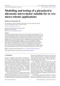
Fig. 2. Moore machine of a gate automata
The main task implementation The main task can be implemented as a composite state machine. It is mean, that the entire main task is composed as a set of composites states. Each of this composite state represents one simple subtask of the main task. Using obvious programming technique each task can be implemented into a while loop: main_task() { while (true) { call substate_1(); call substate_2(); … call substate_n(0); } }
Fig. 1. Moore machine of gate automata
Moore machine The FSM uses only entry actions, i.e., output depends only on the state. The advantage of the Moore model is a simplification of the behaviour. Consider a parking gate. The FSM has four states, “opened_gate”, “opening_gate”, “closing_gate”and “closed_gate”. The state machine recognizes four commands: "open_gate“, "close_gate“, “is_opened” and “is_closed” which trigger state changes. The entry action in state "Opening" starts a motor opening the gate, the entry action in state "Closing" starts a motor in the other direction closing the door. The command “is_opened” turn FSM from “opening_gate” state to “opened_gate” and so on. States "Opened" and "Closed" stop the motor when fully opened or closed. They signal to the outside world (e.g., to other state machines) the situation: "door is open" or "door is closed".
The substate may have following structure: subtate_n() { switch (state) { case state_1: provide_state1(); break; case state_2: provide_state2(); break; … case state_n: provide_staten(); } }
85
returnStateMachineAndContinue n macro combines the actions on the two previous macros. At first it stores the actual address + length_macro to actual_entry_task[n]. Then jump to entry point of the task scheduler. Each task begins with macro: entryPointTaks n. It increment number_of_tasks variable and store the actual address to actual_entry_task[n] and entry_taks[n].
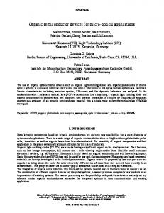
Fig. 3. State machine of the main task and structure of a subtask
The state variable has been a global variable. This program structure may be representing as a state machine. Structure of a composed state is given on figure. Transitions S1, S2, S3 and S4 selected the actual state, for example S1 transition select the State1 and so on. Transitions T1, T2, T3 and T4 are transitions to the next step. The main task exploits a data structure which contains: structure main_task_descriptor { int number_of_tasks; pointer entry_task[n]; pointer actual_entry_task[n]; int mask_task; int actual_task; }
Fig. 4. Implemetation of one subtask as a state machine
The value of the number_of_tasks variable is the number of all task, entry_task[n] contains an entry point of echo of the total number n tasks, where the n is the constant of maximum implemented tasks. Variable actual_entry_task[n] include actual state address of each of all implemented tasks, the mask mask_task is a variable, which bits masks corresponding tasks, that set bit mean unmask, running task, zero bit mean mask task, which is exclude form executing. The actual_task variable consists of the number of the actually executed task. The implementation (Fig. 4) of each state may be done using macros. The first of them: setStateMachine n stores the actual program counter main_task_desriptor[n ]. The second of macros,
to
the
returnStateMachine Fig. 5. Structure of tasks and timing
jump to entry point of the task scheduler. The third 86
This dual storing preserve the task reset. The main part of the task scheduler does:
Acknowledgements This research was supported in part by (1) „Centre for Applied Cybernetics“, Ministry of Education of the Czech Republic under project 1M0567, (2) „SMEW – Smart Environments at Workplaces“, Grant Agency of the Czech Republic, GACR P403/10/1310, (3) „SCADA system for control and monitoring of processes in Real Time“, Technology Agency of the Czech Republic, TACR, TA01010632 and (4) "User Adaptive Systems", VSB Technical University of Ostrava under project SP/2011/22.
while (true) { sheduller_entry_point: do { if (main_task_descriptor. actual_task > main_task_descriptor. number_of_tasks) { main_task_descriptor. actual_ task=0; break; } main_task_descriptor. actual_task++; } while (mask_task && (main_task_descriptor. actual_ task>>1)) jump main_task_descriptor. actual_entry_task [actual_ task ]; }
References 1. Posadas H., Adamez J. A., Villar E., Blasco F., Escuder F. RTOS modeling in System C for real-time embedded SW simulation: A POSIX model // Design Automation for Embedded Systems, 2005. - Vol. 10. – Iss. 4. – P. 209-227. 2. Tomiyama H., Chikada S., Honda S., Takada H. An RTOS-based design and validation methodology for embedded systems // IEICE Transaction on Information and Systems, 2005. - Vol. E88D. – Iss. 9. – P. 2205-2208. 3. Barkalov A., Titarenko L., Hebda O. Synthesis of Moore finite state machine with nonstandard presentation of state codes // Przeglad Elektrotechniczny, 2010. - Vol. 86. – Iss. 9. – P. 134-136. 4. Dziurzanski P. Modelling of complex systems given as a mealy machine with linear decision diagrams // Lecture Notes in Computer Science, 2003. - Vol. 2658. – P. 758-765. 5. Krejcar O. Problem Solving of Low Data Throughput on Mobile Devices by Artefacts Prebuffering // EURASIP Journal on Wireless Communications and Networking. – Hindawi, 2009 – Vol. 2009. Article ID 802523. – P. 1–8. DOI 10.1155/2009/802523. 6. Krejcar O., Frischer, R. Detection of Internal Defects of Material on the Basis of Performance Spectral Density Analysis // Journal of Vibroengineering. – Kaunas, 2010. – Vol. 12. - No. 4. - P. 541-551. 7. Krejcar O., Frischer R. Non Destructive Defects Detection by Performance Spectral Density Analysis // Sensors – MDPI Basel, 2011. – Vol. 11. - No. 3. - P. 2334-2346. 8. Brida P., Machaj J., Duha J. A Novel Optimizing Algorithm for DV based Positioning Methods in ad hoc Networks // Electronics and Electrical Engineering. – Kaunas: Technologija, 2010. – No. 1(97). – P. 33–38. 9. Dodiu E., Graur A., Gaitan V. G. Hard-Soft Real-Time Performance Evaluation of Linux RTAI Based Embedded Systems // Electronics and Electrical Engineering. – Kaunas: Technologija, 2010. – No. 8(104). – P. 51–56.
In the main loop while(1) jump to actual entry point of each of unmask tasks. The loop breaks when all task are executed. The mask task has set to zero corresponding bits in mask_task variable. The periodically called auxiliary tasks have the same scheduler, which is call in predefined time period. Interrupt task are implemented as en interrupt routine. The structure of the base part of RTS is given on the figure. Conclusions The proposed method minimizes the memory occupation of the controller and with only minimum processor resource will implement very light RTOS system. Only minimum of number of instructions is used for switching of tasks. Then lead to some restrictions such the routines must be reentrant. The implementation of periodic task is based on the timer interrupt and the principle of the scheduling is the same using in non periodic task scheduler.
Received 2011 02 14 O. Krejcar, I. Spicka, R. Frischer. Micro Operation System for Microprocessor Applications // Electronics and Electrical Engineering. – Kaunas: Technologija, 2011. – No. 8(114). – P. 83–88. To implement Real-time applications for embedded systems we often using microprocessor systems. Especially when using singlechip microprocessors, we are limited with size of the operation and program memory. Then it appears to be disadvantage to use conventional RTOS, which occupy unnecessarily amount of memory, and most of their services will remain unused. The first papers part is intended to the description of the general management philosophy of the microprocessor applications. There are set goals that should easy control of the separate tasks should meet. It is shown, that the appropriate strategy is to separate processing of input signals, custom application and output signals into CPU peripherals. To synchronize the processes in embedded applications is sufficient to implement the wait states, the sleeps state, and some synchronization means. Presented system includes subsystems: (a) the cooperative management as many as eight to sixteen tasks for time-independent role and (b) preemptive multitasking for time role management. In this mode are solved objective tasks of numerical control and implementation of PID controllers. The second papers part then show concrete sample applications of digital control, including operator control. The proposed solution will bring simplified design of digital control applications, when the commercially delivered applications are unnecessary robust and solve task like file management etc.
87
Proposed solutions will reduce tasks management the minimum, so that minimizes memory demands of the microprocessor units with providing basic management tasks. Ill. 5, bibl. 9 (in English; abstracts in English and Lithuanian). O. Krejcar, I. Spicka, R. Frischer. Mikrooperacijų sistemų taikymas mikrovaldikliuose // Elektronika ir elektrotechnika. – Kaunas: Technologija, 2011. – Nr. 8(114). – P. 83–88. Mikrovaldikliai dažnai taikomi realaus laiko sistemoms įdiegti. Neretai naudojamas vienas mikrovaldiklis, turintis ribotą funkcijų skaičių ir riboto dydžio programinę atmintį. Pateikiama mikrovaldiklių taikymo strategija. Sinchronizuojant procesus svarbu tinkamai aprašyti sinchronizavimo eiliškumą ir įvertinti vėlinimą. Pateikta sistema sudaryta iš posistemių. Naudojant patobulintą PID reguliatorių, pateikiamas objektyvių užduočių sprendimas iš eilės. Antrojoje straipsnio dalyje pateikiama konkrečių programų pavyzdžių. Pateiktieji pasiūlymai leis supaprastinti užduočių valdymą, todėl sumažės reikalinga atmintis. Il. 5, bibl. 9 (anglų kalba; santraukos anglų ir lietuvių k.). .
88