Available online at www.sciencedirect.com
ScienceDirect Procedia Technology 24 (2016) 1194 – 1202
International Conference on Emerging Trends in Engineering, Science and Technology (ICETEST - 2015)
Microcontroller Based Orbital Motion Shaker Arshi Mohini* Meccano instruments, Pune,411042,Maharashtra, India
Abstract A novel procedure of controlling various environmental conditions, shaking speed and duration for shaking of liquid/ semi solid required for microbiology/ chemical research laboratories with the use microcontroller is presented in this paper. The Microcontroller monitors and controls the environmental conditions i.e. humidity, temperature and also provides selectable speed, duration of orbital motion shaker. The system consists of orbital motion producing mechanism, the enclosure for controlled conditions, instruments to control environmental conditions, feedback instruments in order to establish control and microcontroller system which provides programming, interlock and protection for conditions required. This advance microprocessor control ensures reproducible results and operator convenience. System interlocks are also provided in order as a safety measures towards samples examined or cultured by not allowing deviation from the programmed conditions. Microcontroller also ensures self correction in incubation, refrigeration or humidity controls by taking continuous feedback from field instruments. The control system becomes significant as it provides reproducibility in enzyme reactions like aeration in liquid or faster cell growth rate.
© byby Elsevier Ltd.Ltd. This is an open access article under the CC BY-NC-ND license © 2016 2016The TheAuthors. Authors.Published Published Elsevier (http://creativecommons.org/licenses/by-nc-nd/4.0/). Peer-review under responsibility of the organizing committee of ICETEST – 2015. Peer-review under responsibility of the organizing committee of ICETEST – 2015 Keywords: Embedded system; Humidity control; Pulse width modulator ; Microcontroller; Temperature control.
1. Introduction The paper aims to elucidate design of a system with help of a microcontroller [1] to control environment inside a closed chambers. Due to incorporation of microcontroller a low cost, easy, accurate and fast control over various environmental conditions is possible. _____________ *Arshi Mohini. Tel +919765719062 Email:
[email protected]
2212-0173 © 2016 The Authors. Published by Elsevier Ltd. This is an open access article under the CC BY-NC-ND license (http://creativecommons.org/licenses/by-nc-nd/4.0/). Peer-review under responsibility of the organizing committee of ICETEST – 2015 doi:10.1016/j.protcy.2016.05.079
Arshi Mohini / Procedia Technology 24 (2016) 1194 – 1202
Many parameters cans be controlled using the concept illustrated in this paper but in the system designed the parameters controlled are limited to: 1. Temperature 2. Humidity 3. Speed of rotation 4. Door Lock 5. Light requirements The system controls 3 parameters- Temperature [2], humidity and speed with the help of a Microcontroller, which makes this product less costly. Door switch interlock is also provided in the system to stop spinning of motor in order to prevent any hazard. For orbital shaking we are using Triple Eccentric Counter balance Drive, driven by an AC motor. Also the user may acquire current data and can plot graph of temperature and humidity versus time. This application of microcontroller will facilitate extensive research in scientific experiments in pharmaceutical and chemical fields due to its very low cost. The system described works in three modes i.e. manual mode, programming mode and maintenance mode which are discussed with more details in other section of the paper. The primary advantage of this system is that is has no size constraints. The system can be small and compact for laboratory practices or can be very large for industrial application as the drivers and sensors can be changed according to application but the programmed microcontroller can remain same. 2. Literature Survey There are similar products in the market. But the existing products in market either allow only shaking of the chemicals in the flask by controlling speed of AC motor used for shaking [3] or provide orbital shaking with temperature control only [4], i.e. maximum two parameters are measured and controlled i.e. temperature and speed. Also the existing systems use PLCs [5] which makes them expensive and complicated as for processing of parameters signal conditioning at multiple stages is required. But with microcontroller signal conditioning at only one stage is required. Thus it can be seen that the system showed in this paper is cost effective due to the use of microcontroller and provides effective and accurate control for more than two parameters. This provides the potential users to perform chemical processes which involve control over humidity, temperature and speed of shaking at same time which is not provided by existing products in market. Also the different modes provided in our system are not readily available in today’s market. Most of the affordable existing systems provide only manual mode in contrast to the discussed system.
3. Application The advancement of medical science and pharmaceuticals necessitates highly accurate and efficient laboratory instruments [6]. The system described in this paper is highly efficient yet simple in design. The combination of cost effectiveness and technological aspects of the system makes it a competitive solution in today’s market [7]. Due to availability in different size the system can be used in chemical research laboratories, pharmaceutical laboratories, microbiology laboratories and steel industries for chemical analysis of different materials. The laboratory processes which can be facilitated by this system are: 1. Aeration: To increase air content in any given sample. This process is widely used in aerated drinks industry and for fermentation of yeast 2. Prevention of skin formation: The content of proteins in liquid allows skin formation on the surface which may hinder certain type of chemical analysis. By shaking continuously or periodically the system prevents the onset of relaxation process of surface (immobile surface), thus avoiding skin formation. 3. Vigorous mixing: This process is generally done to dispel dissolved gases, scatter particles, and uniformly mix samples e.g. blood samples. The system facilitates this by providing desired temperature, humidity and desired speed of mixing
1195
1196
Arshi Mohini / Procedia Technology 24 (2016) 1194 – 1202
4. 5.
Fast cell growth rate: By providing ambient temperature and humidity cultivation of various bacteria cultures can be accelerated. Biochemical Assays: The convenience to select the set points of different parameters provided by the users helps easy preparation of various chemical compounds. These compounds can be used for various purposes like pre-treatment of various enzyme reactions.
4. Future Scope 1.
2. 3. 4. 5. 6.
The system can be incorporated with a ‘Look Ahead’ function in which the effect of humidity on temperature and vice versa can be compensated with help of a program module in microcontroller for the system to attain stable and desired set-points of the parameters. The system can also have a feature to raise an alarm and send a text message or SMS to warn the administrator if the chamber’s environmental conditions and speed is above normal. The system can be introduced with water or oil bath. This can be achieved by introducing thermally insulated container (vessel) with pump for circulating fluid. Addition of Programmable Photosynthetic Light array/ Ultraviolet Germicidal Lights will have the additional application in Micro biology Lab. Introduction of gassing port for inserting inert or necessary gas can allow different experiments in Mechanical/ Microbiological/ Chemical Labs. Space like vacuum conditions can be simulated by using Vacuum Chamber Instead of Humidity control. This opens up possibilities for conducting studies for a whole range of space related applications.
5. system
overview
The basic function of this system is to control the temperature, humidity and speed in a chamber called orbital motion shaker. Figure 1 illustrates the schematics of the system:
Figure 1: System Schematic
The system consists of temperature sensing module, humidity sensing module, motor speed control module, microcontroller, LCD display and keypad. In the experimental setup of the system for heating purpose a heating coil was used and for cooling purpose compressor was used. For the purpose of humidification air pump was used and for dehumidification vaporizer was used. Pulse width modulation was used to control the speed of motor. The
1197
Arshi Mohini / Procedia Technology 24 (2016) 1194 – 1202
system works in three modes i.e. manual mode, programming mode and maintenance mode. In manual mode set points for the parameter are given and parameters are controlled to reach the set points. After set points are reached the process ends. In programming mode number of steps is given in the beginning. Each step has unique set points for parameters for specified time. Once the START key is pressed the system controls the parameters at each step. The process ends only after every step is completed. Maintenance mode is used to offset any error in beginning of the process. The working of the system can be understood from the flowcharts presented in figure 2 and figure 3.
Figure 2
Figure 3
5.1 Temperature Sensor The temperature sensor used in this project is LM35 [8] as the scale factor is .01 V/ o C, it does not require any external calibration or trimming, maintains an accuracy of +/-0.4 o C at room temperature and +/- 0.8 o C over a
1198
Arshi Mohini / Procedia Technology 24 (2016) 1194 – 1202
range of 0 o C to +100 o C, draws only 60 micro amps from its supply and possesses a low self-heating capability. The sensor self-heating causes less than 0.1 o C temperature rise in still air. Also the sensor circuitry is sealed and not subject to oxidation. LM35 was used for laboratory application, for industrial application any other more suitable temperature sensor can be used.
5.2 Humidity Sensor The humidity sensor used is SY HS 220[9] and is shown in Figure 5. This sensor module is readily available and is very cost effective. The module has a circuit which conditions the output into suitable form. The gain of the sensor module can be adjusted by the resistance pot. The sensor provides the information about humidity in the range 30%RH to 90%RH. The sensor module is very compact hence allows easy placement of sensor in the system. Along with the above advantages the current consumption of the sensor module is also very low (below 0.3 mA). All these benefits make SY HS 220 an appropriate choice for this system.
Figure 4: LM35 Temperature sensor
Figure 5: SY HS 220 Humidity sensor
5.3 Microcontroller Microcontroller is the heart of the system. The various controllers considered for this system were 8051[10],[11] PIC, AVR, ARM[12], etc. 8051 does not have internal ADC and internal PWM channels and is also relatively slower. PIC is slower and ARM is relatively expensive and also the software is not readily available on internet. The AVR AT Mega 8535[13] microcontroller is a high performance and low power 8 bit microcontroller with 4 Input / Output ports. It has advanced RISC architecture with 130 powerful instruction set. It has two 8 bit timers and one 16 bit timer and 4 PWM channels. The microcontroller has 512 bytes of EEPROM. The microcontroller has an inbuilt 8 channel 10-bit ADC that has been used for converting the analog output on the signal conditioning circuit to digital form. The entire data processing is achieved with the help of microcontroller. It is also responsible for synchronization of various devices connected to the system. The Reset pin of the Keypad is directly given to the RESET pin of the Microcontroller. Configuration of the Internal Blocks of Microcontroller: The microcontroller AT-MEGA 8535 provides the facility to program the controller in both assembly language and C language. For the configuration of this system C language is used. 5.3.1
Analog to Digital Converter
AVR At-Mega 8535 has an inbuilt 10 bit ADC used to convert analog signal from the sensors into digital output. With the use of the ADLAR bit in the ADMUX register the ADC can be configured as an 8 bit ADC. The ADC module has 3 registers which are used for the configuration of ADC: 1. ADC Data register (ADCL and ADCH). 2. ADMUX (ADC Multiplexer Selection Register) 3. ADCSRA (ADC Control and Status register
Arshi Mohini / Procedia Technology 24 (2016) 1194 – 1202
5.3.2
1199
Pulse Width Modulator
Steady speed for a given load can be maintained by using a Pulse Width Modulator (PWM). By changing the width of pulse applied to the motor the amount of power provided to the motor can be increased or decreased, thereby increasing or decreasing the speed. There are 3 timers in AT Mega 8535 which can be used as wave generators. The advantage of using an inbuilt PWM is that it provides the option of programming the time period and duty cycle as per requirement. Timer 2 is used as PWM in this system. Timer/Counter Control Register 2 (TCCR2) is configured for this purpose. TCCR2 is set to 0x69 in order to set all the desired bits for fast PWM mode. The wave generated by PWM is given optoisolator [14], then inverter [15] from which it is given as input to LM358 [16] and then to RC filter which averages and integrates the wave and gives DC voltage level corresponding to the speed given by the user. This voltage is given to the Variable Frequency Drive (VFD) [17] which generates a frequency corresponding to the voltage level and the frequency is given to the AC Motor. 5.4 Display A display device enables user to make parameter settings and provides with continuous monitoring of process parameters. 20×4 LCD is used for this purpose. The microcontroller controls the initialization and the data output to the LCD. PORTC is used as data port for the LCD and the PORTA pins numbered from 5 to7 are used as control pins for the LCD. LCD or the display of our system is as shown in the Figure 6.
Figure 6: Display and keypad of our system
5.5 Keyboard A keyboard is provided to the user to make desired parameter settings and allow set different set points for various purposes. The keypad of the system is: x RESET x INCREMENT x DECREMENT x HOLD x START/STOP x SELECT x 5.6 Relays
1200
Arshi Mohini / Procedia Technology 24 (2016) 1194 – 1202
Solid state relays are used to turn on and off the various components of the system. A solid-state relay (SSR) is an electronic switching device that switches states when an external voltage is applied. SSR has a small control signal that controls a larger load current or voltage. It consists of a sensor which responds to an appropriate input (control signal), a solid-state electronic switching device which switches power to the load circuitry, and coupling mechanism to enable the control signal to activate this switch without mechanical parts. Lifetime is high as there are no moving parts to wear and no contacts to pit or build up carbon and also there is no mechanical wear and tear. Output resistance remains constant regardless of frequency of usage. 3-32V can be given as an input to the relay and output is 5A-330V AC.
6. Testing The following modules of the system were tested individually: x LM35 x SY HS 220 x Keyboard x Display x PWM block x Relays x Entire system testing 1.
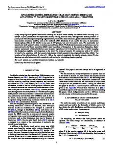
Signal conditioning [18], [19] of LM35 was tested by noting the signal Voltage for various temperatures. Table 1 shows Testing results of LM 35 and figure 7 depicts the graph:
Table 1: Testing Results of Signal Conditioning of LM 35 Serial Present Output Expected No. Temperature(ºC) Voltage(mV) Voltage(mV) 1
25
249
250
2
30
297
297
3
35
347
347
4
60
596
596
5
64
636
636
Figure 7: Graph of LM 35 output versus Actual Temperature
2.
Testing of Signal Conditioning For Humidity Sensor: Table 2 shows results obtained for the signal conditioning circuit Humidity sensor and figure 8 depicts the graph.
Sr No.
3.
Humidity (%)
Sensor Output(mV)
Final Output(mV)
Expected Output(mV)
1
30
990
300
300
2
34
1122
338
340
3
41
1353
408
410
4
56
1848
557
560
Table 2: Testing Results SY HS 220
Figure 8: Graph of SY HS 220 output versus Actual Humidity
Testing Of LCD: The display is completely black when pin no. 2
Arshi Mohini / Procedia Technology 24 (2016) 1194 – 1202
is given +5V along with its ground connections. A simple program for displaying ‘LABORATORY SHAKER’ was successful. 4.
Testing Of Keypad: Key detection was checked successfully, Key denouncing was done correctly. A simple program for increment and decrement of parameters using keypad was successful.
5.
Testing for Signal Conditioning of PWM Going to Motor: PWM output being generated by the microcontroller was successfully checked. 6N137 i.e. the optocoupler IC, CD40106, LM358 and RC filter generated desired output when checked individually and together
6.
Testing of Relays on PCB: Respective Port Pins of relays were made high individually to check if all the loads like Heater, Compressor or Fan were running.
7.
Result of entire system testing:
For testing purpose, a testing panel was made which had all the components i.e. the signal conditioning blocks of LM35 and SY HS 220 along with signal conditioning block of PWM to motor were assembled together as shown in figure 9. The system was assembled as described in system overview section. All the parameter set points were given to system at once using the keypad of the system and were visible on the LCD display of the system. The temperature and humidity variations to reach set point are noted. The set point and the current values are compared and accordingly Temperature and Humidity are increased and decreased.
Figure 9: Testing Panel
Figure 10: Graph showing temperature and humidity for complete system.
The graph is plotted for the condition where set point of temperature and humidity greater than current temperature and humidity. The LM35 and SY HA 220 used for sensing purpose give accurate reading as shown in figure 10. 7. Conclusion A system designed is capable of producing a controlled environment as per user’s requirement. The parameters being monitored and controlled are temperature, humidity and speed of shaking. The temperature sensor LM35 and the humidity sensor SY HS 220 are successfully interfaced as input. The system is also correctly able to drive motor, heater, compressor, vaporizer and air pump as per the environment desired. The entire system fabricated is cost effective and has the capability to respond immediately to any kind of changes. The system is made safe by incorporation of door open alarm which prevents the operation of the system in case the door is opened. Thus system successfully provides necessary functions required in various microbiology labs and pharmaceutical labs at very economical price.
1201
1202
Arshi Mohini / Procedia Technology 24 (2016) 1194 – 1202
8. Acknowledgement This system consumed a lot hard work and time which would not have been possible without Mr Parag Pathak’s enormous support. My team members namely Ekta Ghonge, Prajakta Kale and Shivani Mattoo whole heartedly contributed in successfully developing this system. Also the staff of MKSSS’s Cummins College of Engineering for Women provided with their valuable guidance. It is because of collective effort of these valuable entities that this project was developed successfully.
9. References [1] By Muhammad Ali Mazidi, S. Naimi “The AVR Microcontroller and Embedded System Using Assembly and C” Second Edition. [2] Emerson - Refrigeration Compressor manual [3] Orbital Shaker manufactured by Eltek- http://www.eltekindia.com/Orbital_shaker.html [4] MP 6000 R by Eltek - http://www.eltekindia.com/mp6000r.html [5] MaxQ 6000 Incubated and Refrigerated Stackable Shakers By Thermoscientifichttp://www.thermoscientific.com/en/searchresults.html?keyword=MaxQ%E2%84%A2+6000+Incubated%2FRefrigerated+Stackable+Shakers&ma tchDim=Y [6] Calibration of laboratory instruments- Sheldon S. Myers [Online] [7] The Research lab of 2020-Laboratory Equipment http://www.laboratoryequipment.com/articles/2009/12/research-lab-2020 [8] Texas Instruments LM 35 – Datasheet [9] RhydoLABZ SY-HS 220 – Datasheet [10] Intel MCS-51 8051- Datasheet [11] Microchip P16F87X- Datasheet [12] NXP Semiconductors LPC2141 – Datasheet [13] Atmel AT Mega 8535- Datasheet [14] Fairchild Semiconductor 6N137 – Datasheet [15] Fairchild Semiconductor CD 40106 – Datasheet [16] Texas Instruments LM 358 – Datasheet [17] DELTA Variable Frequency Drive -EL user manual [18] P. Horowitz, W. Hill “The Art of Electronics” Second Edition. [19] Texas Instruments LMC 7660 – Datasheet