Available online at www.sciencedirect.com
Sensors and Actuators B 132 (2008) 525–530
Microfluidic centrifuge of nano-particles using rotating flow in a microchamber Jung Hwan Lee a , Jin Bong Ha a , Yeon Kyeung Bahk a , Sung Hwan Yoon a , Takahiro Arakawa c , Jong Soo Ko a , Bo Sung Shin b , Shuich Shoji c , Jeung Sang Go a,b,c,∗ a
School of Mechanical Engineering, Pusan National University, San 30, Jangjeon-dong, Geumjeong-gu, Busan 609-735, Republic of Korea b Engineering Research Center, Busan, Republic of Korea c Electrical Engineering and Bioscience, Waseda University Tokyo, Japan Available online 22 November 2007
Abstract This paper presents the centrifugation of the nano-particles using the rotating flow in the microchamber. The feasibility of the microfluidic centrifuge was demonstrated numerically and experimentally. The centrifugation of the nano-particles of 300 and 500 nm was visualized by using a high-speed CCD camera and a micro-PIV. In addition, its performance was characterized quantitatively. The experimental results of the mechanical contact-free microfluidic centrifuge showed the same physical phenomena with the conventional one even in its small size. Also, a new finding was obtained that the transient motion influenced the stable operation of the microfluidic centrifuge. © 2007 Elsevier B.V. All rights reserved. Keywords: Centrifuge; Nano-particle; Microfluidic; Rotational flow; Micro-PIV
1. Introduction In bio-technology and medical science, the concentration of a specific protein, DNA or cell containing clinical information is very important to increase the sensitivity of detection and clinical diagnostics. Various technical wises such as capillary electrophoresis, mass chromatography, bead handling and centrifugation have been developed and used practically to obtain the target biomolecules [1–4]. Among them, the centrifugation has been used most commonly due to its powerful separation performance and simple manipulation of mixtures without any labeling and additional biological treatment. The centrifuge uses the sedimentation of the mixed biomolecules of greater and less density. The precipitate separation can be obtained from the centripetal acceleration induced by the mechanical rotation. It means that in order to make the selective sampling of the nano-size proteins or DNAs, the spinning of a rotor requires very high speeds so that its own system becomes ∗ Corresponding author at: School of Mechanical Engineering, Pusan National University, San 30, Jangjeon-dong, Geumjeong-gu, Busan 609-735, Republic of Korea. Tel.: +82 51 510 3512; fax: +82 51 512 5236. E-mail address:
[email protected] (J.S. Go).
0925-4005/$ – see front matter © 2007 Elsevier B.V. All rights reserved. doi:10.1016/j.snb.2007.11.027
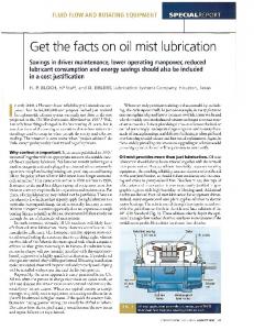
lager. However, the direct contact of the mechanical components at the high speed may result in poor system reliability [5]. This paper presents a mechanical contact-free microfluidic centrifuge using the rotating flow to obtain the high concentration of nano-particles. Its separation performance is evaluated by visualizing the dynamic behavior of the fluorescent nanoparticles. 2. Design of the microfluidic centrifuge Fig. 1 describes the configuration of the microfluidic centrifuge consisting of a microchannel and chamber connected to a extraction channel to guide the centrifuged nano-particles and working mechanism in addition. The streamwise fast flow in the microchannel occurs the momentum transfer at the interface between the microchannel and the chamber due to the interfacial viscosity. This momentum generates the rotating flow in the chamber [6]. Thus, the nano-particles suspended in the chamber fluid rotate simultaneously so that the centripetal acceleration is applied proportionally to the square of their rotational speed on the nano-particles. As a result, they can be centrifuged to the outer from the center of the rotating flow. It is physically identical to the working principle of centrifugation.
526
J.H. Lee et al. / Sensors and Actuators B 132 (2008) 525–530
Fig. 1. Occurrence of the rotational flow in the chamber due to interfacial viscosity and description of the microfluidic centrifugation. (a) 2D velocity vector field with the center of the rotating flow; (b) horizontal velocity profile to the channel flow; (c) vertical velocity profile to the channel flow.
Fig. 2. Velocity distribution of the microfluidic rotational flow induced by the fast flow stream in a 1 inlet–1 outlet.
Fig. 3. Trajectory of the nano-particle with the diameter of 500 nm in the rotation flow.
We first examined the occurrence of the rotating flow in the chamber and the hydrodynamic behavior of the nano-particles by using the numerical simulation of spray module (CFD-ACE) [7–9]. The depth and width of all microchannels were 25 m. The square chamber of 125 m was used. For the inlet condition, the pure water was introduced with an inlet flow rate of 200 l/min. Fig. 2 shows the magnitude of the vertical and horizontal velocity to the streamwise direction in the chamber obtained from the rotating flow. The numerical vector field implies the
Fig. 4. Velocity distribution of the microfluidic rotational flow induced by the fast flow stream in a 2 inlets–2 outlets. (a) 2D velocity vector field and (b) comparative velocity profile.
J.H. Lee et al. / Sensors and Actuators B 132 (2008) 525–530
527
Fig. 5. Microfabrication process of the microfluidic centrifuge. (a) Double-side polished Si wafer; (b) photolithography; (c) DRIE of Si; (d) growth of SiO2 ; (e) photolithography; (f) backside DRIE of Si; (g) removal of SiO2 ; (h) anodic bonding of Si/Pyrex glass. Table 1 Maximum interfacial velocities and Mega-g centripetal accelerations for the various chamber sizes D/d
Interfacial velocity (m/s)
Centripetal acceleration 9.81 × 10⁶ (m/s2 )
1 2 3 4 5
12.27 16.88 20.78 23.53 26.16
1.23 1.16 1.17 1.13 1.12
occurrence of the rotating secondary flow in the chamber. The rotating center did not occur at the center of the chamber but it was located near the outlet because of the sudden expansion–contraction effect of the microchannel and the rapid
momentum loss near the walls. They also brought the asymmetric velocity distribution. Fig. 3 shows the trajectory of a nano-particle of the diameter of 500 nm in the rotating flow. It is identical that the suspended nano-particle in the chamber is centrifuged to the outer wall. In order to overcome the asymmetric velocity distribution, two sides interfacial shear flow was introduced. As shown in Fig. 4, the center of the flow rotation was obtained at the center of the chamber and the velocity was distributed symmetrically. In addition, the centrifugation performance can be expected from the higher density of the rotational flow as compared for the same inlet flow rate of 200 l/min (Fig. 4(b)). Especially, in designing the microfluidic centrifuge, we considered the ultra-centrifugation able to realize the mega gravity magnitude of the centripetal acceleration. The width and depth of the inlet microchannel were fixed with 25 m. The maximum
Fig. 6. SEM images of the fabricated microfluidic centrifuges.
528
J.H. Lee et al. / Sensors and Actuators B 132 (2008) 525–530
Fig. 7. Experimental setup for performance evaluation.
inlet flow rate of 1 ml/min that the commercial syringe pump could provide was considered in simulation. Table 1 shows the maximum velocities at the interface between the microchannel and the chamber and their equivalent centripetal accelerations for the various ratios of the chamber size to the channel size from 1 to 5. The one mega gravity (106 g) can be expected in all cases. 3. Experimental installation For experimental investigation, the microfluidic centrifuge was fabricated on a 400 m-thick both-side polished silicon
wafer by using a double-step deep reactive ion etch (DRIE). The depth and width of the microchannel were 25 m as designed. For optical visualization, a 100 m-thick Pyrex glass (#7740) was anodically bonded with the silicon substrate to form the microchannel. Fig. 5 describes the fabrication process of the fabricated microfluidic centrifuge and the fabricated microfluidic centrifuges were shown in Fig. 6. In order to evaluate the centrifugation performance, we infused the deionized water mixed with fluorescent nanoparticles of 300 and 500 nm by using the syringe pump (Harvard 4400). The inlet flow rate was increased from 60 to
Fig. 8. Comparative centrifugation performance of the fluorescent particles at the inlet flow rate of 200 l/min. (a) Centrifugation of nano-particles of 300 nm and (b) centrifugation of nano-particles of 500 nm.
J.H. Lee et al. / Sensors and Actuators B 132 (2008) 525–530
200 l/min to investigate the centrifugation according to the increasing interfacial flow velocity. However, over the inlet flow rate of 200 l/min, it is very difficult to keep the tube held due to high flow resistance. For the visualization of the rotating flow in the microchamber, a high-speed CCD camera was installed. Fig. 7 illustrates the experimental setup for the performance evaluation. In spite of using the high performance camera to take 1000 images per a second, the quantitative movement of nanoparticles could not be obtained. However, it was possible to visualize qualitatively that the nano-particles were centrifuged from the center of the rotation to the outer wall with rotation. Thus, we replaced the high-speed CCD camera with a micro-PIV system [10,11]. The incident ray from the Nd:YAG laser stimulates the fluorescent nano-particles and the ray with a different wavelength is emanated from them. By using an optical filter, the emanated ray is only filtered and the dynamic movement of the fluorescent nano-particles can be analyzed. 4. Results and discussions Fig. 8 shows the centrifugation performance of the fluorescent nano-particles of 300 and 500 nm for the inlet flow rate of 200 l/min with respect to time. The depletion region of the fluorescent nano-particles was generated and grew from the center of rotation with time. The nano-particles of 500 nm were centrifuged much faster than the nano-particles of 300 nm. Especially, the nano-particles of 500 nm were perfectly centrifuged within 10 s. It is determined that the larger the size, the faster the centrifugation can be obtained. In addition, the centrifuged nano-particles were collected through the concen-
Fig. 9. Centrifugation performance of nano-particles of 500 nm for the increasing inlet flow rate. (a) Definition of ratio of centrifuged area and chamber size and (b) comparative centrifugation.
529
Fig. 10. Velocity vector filed washing the chamber away during the transient motion.
tration channel. It was visualized that the channel became bright because of concentration of nano-particles as time went by. We also examined the centrifugation by increasing the inlet flow rate for the quantitative evaluation. The depletion region was not circle but an ellipse. Thus, we defined the ratio of the size of the depletion region to the chamber size as a parameter of centrifugation. Fig. 9 shows that by increasing the inlet flow rate, which implies the faster rotation, it took a shorter time to grow the depletion area of the suspended nano-particles of 500 nm. However, for the centrifugation of nano-particles of 500 nm, it was hard to obtain the ratio of the size of the depletion region to the chamber size. However, the microfluidic centrifuge experiences the transient motion in reaching the stable rotational flow in the microchamber because of the presence of pressure damping in the flexible silicone tube. Fig. 10 shows the velocity vector field at a transient motion. Instead of the rotational flow, it caused to wash the nano-particles residing in the chamber away. In order to obtain the reliable centrifugation, the opening area and the chamber size must be taken into account in advance. In case of the microfluidic centrifuge with two inlets and two outlets, the promising numerical results were obtained with the symmetric velocity distribution and the faster rotation for the same inlet flow rate. However, in the experimental results, the
Fig. 11. Flow directions in the microfluidic centrifuge with two inlets and two outlets.
530
J.H. Lee et al. / Sensors and Actuators B 132 (2008) 525–530
inlet flow was divided and drained into two outlets, differently from design (Fig. 11). 5. Conclusions Based on the simulated ultra centrifuge with mega gravity, the microfluidic centrifuge was fabricated and its centrifugation performance was successfully shown by centrifuging the fluorescent nano-particles of 300 and 500 nm. It is concluded that the nano-particles are centrifuged faster for the increasing inlet flow rate and the larger nano-particles are centrifuged earlier. These show exactly the same physical behaviors with the conventional centrifuge. It is newly visualized that the microfluidic centrifuge can be used to concentrate nano-particles. Further works for the reliable centrifugation requires the elimination of the transient motion by considering the opening area of the chamber and its size. Also, in order to enhance the efficiency of centrifugation, a new design of the microfluidic centrifuge must be advanced. References [1] P. Dario, et al., Micro-systems in biomedical applications, J. Micromech. Microeng. 10 (2000) 235–244. [2] I.-F. Zhurnal, Theory of centrifugal sedimentation of large particles, Eng. Phys. Thermophys. 32 (5) (1977) 865–869. [3] Y. Hayashi, R. Matsuda, Information theory of optimization in chromatography, Chromatographia (1990) 446–448. [4] D. Li, Electrokinetics in Microfluidics, Elsevier, Amsterdam, 2004. [5] J.D. Rodgers, F. Cericola, J.W. Doggett, M.L. Young, Vibrafuge: Combined Vibration and Centrifuge Testing, in: Shock and Vibration Symposium. SAND89-1656C, 1989. [6] J.P. Veerapen, B.J. Lowry, M.F. Couturier, Design methodology for the swirl separator, Aquacultural Eng. 33 (2005) 21–45. [7] M. Turkyilmazoglu, Influence of centrifugal forces on the development of wave packets in boundary layers with a uniformly valid model, Comput. Fluids 36 (2) (2007) 342–358. [8] W.T. Godbey, B.S. Hindy, M.E. Sherman, A. Atala, A novel use of centrifugal force for cell seeding into porous scaffolds, Biomaterials 25 (2004) 2799–2805. [9] R.J. Townsend, M. Hill, N.R. Harris, N.M. White, S.P. Beeby, R.J.K. Wood, Fluid modeling of microfluidic separator channels, Sens. Actuators B: Chem 111–112 (2005) 455–462. [10] I. Grant, Particle image velocimetry, in: Proceedings of the Institute of Mechanical Engineers, vol. 211, 1997, pp. 55–76. [11] R.J. Adrian, Particle-imaging techniques for experimental fluid mechanics, Ann. Rev. Fluid Mech. 23 (1991) 261–304.
Biographies Jung Hwan Lee received a MS degree in the school of Mechanical Engineering from the Pusan National University, Busan, Korea, in 2007. Beginning from
March 2007, he has been working at the Renault–Samsung Automotive company in Korea, where he is responsible for the application of micro technology to the car system. His research interests include micro biochemical separation system and MicroThermoFluidics. Jin Bong Ha received a BS degree in the school of Mechanical Engineering from the Pusan National University, Busan, Korea, in 2006. His research topic for thesis is engaged in the investigation of the size-selective separation of particles for bio-application. His research interests include micro biochemical plant and MicroThermoFluidics. Yeon Kyeung Bahk received a BS degree in the school of Mechanical Engineering from the Pusan National University, Busan, Korea, in 2006. His research topic for thesis is the development of a new microfabrication method of the functional glasses. His research interests include micro-biochemical system. Sung Hwan Yoon received a BS degree in the school of Mechanical Engineering from the Pusan National University, Busan, Korea, in 2006. His research topic for thesis is the development of the environment-constrained energy technology. His research interests include micro energy generation system. Takahiro Arakawa received a PhD degree in the school of Electrical Engineering and Bioscience from the Waseda University, Tokyo, Japan, in 2007. His research topic for thesis is the development of the environment-constrained energy technology. His research interests include micro and nano system of biochemical microfluids and micro chemical plant. Jong Soo Ko received a PhD degree in Mechanical Engineering from the Korea Advanced Institute of Science and Technology (KAIST), Taejeon, Korea, in 2000. His doctoral research was engaged in the investigation of IR sensor array. Beginning from September 2000, he had been working at the ETRI in Korea, where he was responsible for the development of a Biochip. From April 2003, he has been working at the Pusan National University. His research interests include microfabrication, sensors and actuators, nanoimprinting and X-ray sensor. Bo Sung Shin received a PhD degree in Mechanical Engineering from the Korea Advanced Institute of Science and Technology (KAIST), Taejeon, Korea, in 2002. His doctoral research was engaged in the investigation of Micro/Nano fabrication using the rapid prototyping technology. From 1990 to 2003, he had served at the KIMM, in Korea. From September 2003, he has been working at the Pusan National University. His research interests include micro/nano fabrication using laser technology. Shuich Shoji received his PhD degree in engineering from Tohoku University, Sendai, Japan. From 1992 to 1998, he was a research associate and an associate professor of Tohoku University. From 1992 to 1997, he was an associate professor of Waseda University. Since 1997, he has been a professor of electronics, information and communication engineering of Waseda University. Jeung Sang Go received a PhD degree in Mechanical Engineering from the Korea Advanced Institute of Science and Technology (KAIST), Taejeon, Korea, in 2001. Beginning from May 2000, he had been working at the Samsung Advanced Institute of Technology (SAIT) in Korea for the investigation and development of MicroCooling Systems. From April 2002, he had performed research on micro and nano system of biochemical microfluids at Applied Chemistry of Tokyo University and Waseda University in Japan. He is currently working at the Pusan National University as an assistant professor. His research interests include micro biochemical plant, environmentconstrained energy technology (E2 technology) and microcooling based on MicroThermoFluidics.