Microfluidic chambers using fluid walls for cell biology Cristian Soitua, Alexander Feuerbornb,c, Ann Na Tanb,c, Henry Walkerc, Pat A. Walshd, Alfonso A. Castrejón-Pitae, Peter R. Cookb,1, and Edmond J. Walsha,1 a Department of Engineering Science, University of Oxford, OX2 0ES Oxford, United Kingdom; bSir William Dunn School of Pathology, University of Oxford, OX1 3RE Oxford, United Kingdom; ciotaSciences Ltd., OX5 1PF Oxfordshire, United Kingdom; dBernal Institute, School of Engineering, University of Limerick, Castletroy, V94 T9PX Limerick, Ireland; and eDepartment of Engineering Science, University of Oxford, OX1 3PJ Oxford, United Kingdom
microfluidics
| fluid walls | tissue culture | sessile drops | interfacial tension
M
icrofluidics addresses the manipulation of tiny volumes, typically less than 1 μL. Despite many proofs of concept involving common protocols in cell biology, uptake of microfluidics by biologists is limited. Some well-known and documented reasons include the cost and complexity of manufacture of microfluidic devices (which might involve soft lithography and clean rooms), concerns regarding biocompatibility (materials used for fabrication like polydimethylsiloxane and the associated solvents are not traditionally applied in cell biology), and the inaccessibility of cells after being introduced into enclosed spaces within devices. This prompts the development of many alternatives, including “open” and “paper-based” microfluidics (1). Microtiter plates are widely used during liquid handling; each is essentially an array of miniature test tubes with 96, 384, or 1,536 wells in a uniform footprint, where wells have working volumes of ∼100 to 400, ∼15 to 150, or ∼3 to 10 μL, respectively. Arrays with more wells and volumes down to a few femtoliters have been developed (2, 3). Arrays of aqueous drops sitting on flat (usually patterned) surfaces and overlaid with an immiscible liquid to prevent evaporation have also been fabricated (4–9); in these, liquid walls/ceilings confine the aqueous phase. The burgeoning field of droplet-based microfluidics also uses fluid walls to confine liquids (10–12). However, compared with the widespread use of microtiter plates, few of these alternatives are incorporated into workflows in cell biology (13); consequently, most still involve volumes of many microliters. A recent method termed Freestyle Fluidics allows fabrication of microfluidic circuits by dispensing cell media in a desired pattern on a Petri dish and overlaying it with an immiscible liquid (14). The aqueous phase is bounded by fluid walls—the interface between water and immiscible liquid. One of the resultant circuits was used in a chemotaxis experiment with bacterial cells, and several benefits compared with traditional circuits were www.pnas.org/cgi/doi/10.1073/pnas.1805449115
demonstrated. Here, we also created microfluidics patterns with fluid walls. However, instead of depositing the aqueous phase in the desired pattern on the substrate and then overlaying the immiscible liquid, we simply reshaped the two fluids already on the substrate and allowed interfacial forces to build fluid walls accurately, reproducibly, and immediately. At the microscale, these fluid walls prove to be strong, pliant, and resilient; they morph above unchanging footprints when nanoliter volumes are added/removed. Although any 2D pattern can be made, we demonstrate the method and its versatility by creating analogs of a familiar experimental platform in cell biology, the microtiter plate. We show that mammalian cells grow and respond to stimuli normally and that worm eggs develop into adults. We also demonstrate many basic manipulations involved in cell biology (i.e., cell feeding, replating, cloning, and cryopreservation), plus some common downstream workflows (i.e., fixation/immunolabeling, cell lysis/RT-PCR, transfection/genome editing). Furthermore, we go beyond what is possible with existing microfluidics and reconfigure the fluidic structures in real time. We suggest that this method provides biologists with an easy entrée into microfluidics, without the usual expertise/equipment requirements, while also providing the freedom to create and reconfigure designs on demand. Significance Despite improvements in our ability to manipulate eversmaller volumes, most workflows in cell biology still use volumes of many microliters. We describe a method for creating microfluidic arrangements containing submicroliter volumes. It exploits interfacial forces dominant at the microscale to confine liquids with fluid (not solid) walls. We demonstrate many basic manipulations required for cell culture and some widely used downstream workflows. The method eliminates many problems associated with the fabrication of conventional microfluidic devices, thereby providing a simple on-demand approach for fabrication of microfluidic devices using materials familiar to biologists. Author contributions: C.S., A.F., P.R.C., and E.J.W. designed research; C.S., A.N.T., and E.J.W. performed research; H.W., P.A.W., and E.J.W. contributed new reagents/analytic tools; C.S., A.F., A.N.T., A.A.C.-P., P.R.C., and E.J.W. analyzed data; and C.S., A.F., P.A.W., A.A.C.-P., P.R.C., and E.J.W. wrote the paper. Conflict of interest statement: Oxford University Innovation—the technology transfer company of the University of Oxford—has filed provisional patent applications on behalf of C.S., A.F., P.R.C., and E.J.W. partly based on this study. A.F., H.W, P.R.C., and E.J.W. each hold equity, or rights to equity, in Iota Sciences Ltd., a company that is exploiting this technology. Iota Sciences Ltd. provides a scholarship for C.S. and partially funds salaries and research of A.F., A.N.T., H.W., and P.A.W. This article is a PNAS Direct Submission. This open access article is distributed under Creative Commons Attribution-NonCommercialNoDerivatives License 4.0 (CC BY-NC-ND). 1
To whom correspondence may be addressed. Email:
[email protected] or
[email protected].
This article contains supporting information online at www.pnas.org/lookup/suppl/doi:10. 1073/pnas.1805449115/-/DCSupplemental.
PNAS Latest Articles | 1 of 8
ENGINEERING
Many proofs of concept have demonstrated the potential of microfluidics in cell biology. However, the technology remains inaccessible to many biologists, as it often requires complex manufacturing facilities (such as soft lithography) and uses materials foreign to cell biology (such as polydimethylsiloxane). Here, we present a method for creating microfluidic environments by simply reshaping fluids on a substrate. For applications in cell biology, we use cell media on a virgin Petri dish overlaid with an immiscible fluorocarbon. A hydrophobic/fluorophilic stylus then reshapes the media into any pattern by creating liquid walls of fluorocarbon. Microfluidic arrangements suitable for cell culture are made in minutes using materials familiar to biologists. The versatility of the method is demonstrated by creating analogs of a common platform in cell biology, the microtiter plate. Using this vehicle, we demonstrate many manipulations required for cell culture and downstream analysis, including feeding, replating, cloning, cryopreservation, lysis plus RT-PCR, transfection plus genome editing, and fixation plus immunolabeling (when fluid walls are reconfigured during use). We also show that mammalian cells grow and respond to stimuli normally, and worm eggs develop into adults. This simple approach provides biologists with an entrée into microfluidics.
CELL BIOLOGY
Edited by David A. Weitz, Harvard University, Cambridge, MA, and approved May 21, 2018 (received for review March 28, 2018)
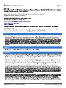
Results Methodology. Fig. 1A illustrates the fabrication of a 2 × 2 grid.
The bottom of a standard polystyrene Petri dish is completely covered with cell medium, excess medium is removed, and the residual thin film is overlaid with an immiscible liquid. This overlay can be less dense than water, like a hydrocarbon. Perhaps counterintuitively, it can be denser, like FC40—a transparent
A
C
D
B
E
Fig. 1. Reverse printing. (A) Principle. A Petri dish is filled with DMEM plus 10% FBS, most medium is removed, and the residual thin film is overlaid with FC40 (shown in green). A hydrophobic stylus is lowered to touch the dish and to bring FC40 to the surface. As the stylus moves horizontally, medium is pushed aside and FC40 takes its place. This creates a track of FC40 pinned to the substrate and a liquid wall of FC40 dividing the aqueous layer. Drawing more lines creates a grid. (B) A 32 × 32 grid made in ∼4 min. After printing, 70 nL of yellow or blue dye is added to each chamber. (C) A high-density grid made with a thin stylus (73% surface covered by medium). (D) Adding and subtracting medium. (i) The contact angle is θE). (iii) Medium can be removed without altering the footprint until θR is reached (70°. (E) Stylus width determines wall width. Lines were made using styli with wider and narrower tips than in B, and regions between chambers were imaged.
2 of 8 | www.pnas.org/cgi/doi/10.1073/pnas.1805449115
fully fluorinated liquid (density 1.855 g/mL) that is widely used in droplet-based microfluidics; at the microscale, effects due to gravity and buoyancy become negligible, and interfacial forces pin the aqueous phase to the plastic. A hydrophobic and fluorophilic stylus with a conical tip made of polytetrafluoroethylene (Teflon) and held by a three-axis traverse (a “printer”) is then lowered through both liquids until it just touches the dish. Because FC40 wets Teflon and polystyrene better than water, the tip (now coated with FC40) brings fluorocarbon down to wet the substrate. When the stylus moves laterally, the aqueous liquid is displaced from the surface to leave a track of FC40 pinned to plastic by interfacial forces. Drawing more lines creates a grid. Grids with few or many chambers can be made in minutes (Fig. 1 B and C, SI Appendix, Fig. S1, and Movie S1); for example, chamber density in the grid in Fig. 1C is analogous to that of a microplate with 393,216 wells. Colored dyes are often pipetted into chambers to aid visualization; they play no role in stabilizing liquid structures. Individual chambers are used much like wells in conventional microplates; liquids are simply pipetted into (or removed from) them through FC40 instead of air (Fig. 1D). This can be achieved without altering the footprint on the dish. Consider a sessile water drop in air sitting on a standard polystyrene Petri dish. The drop is shaped like the cap of a sphere, and its footprint depends on the equilibrium contact angle (the angle θE, at the air– water–substrate interface) (15, 16). When tissue culture medium without serum replaces water, θE is ∼50°, and θE increases to ∼70° if FC40 replaces air (14). Slightly more medium can now be added without increasing the footprint, up to a limit determined by the advancing contact angle, θA (θA > θE); once θA is breached, footprint area increases. Similarly, when medium is removed, the footprint shrinks once the receding contact angle, θR, is reached. However, θR is 70°. The significant difference between θA and θR allows the addition and removal of liquids above unchanging footprints (Fig. 1 D, v). The spacing between chambers can also be varied using styli with wider or narrower tips (Fig. 1E). FC40 plays several additional roles. Fluorocarbons like FC40 were developed during the Manhattan Project as materials that could resist attack by highly reactive uranium hexafluoride; consequently, they are arguably the most inert liquids known. They are also the carrier fluid of choice in droplet-based microfluidics. In addition, FC40 carries the vital gases (O2 and CO2) so effectively that it has been used as a blood substitute (17), and FC40’s close relatives have been used for liquid ventilation of human preterm neonates (18, 19). FC40 also prevents the underlying aqueous layer from evaporating (the solubility of water in FC40 is 14 d in conventional plates). Discussion We describe a microfluidic platform for miniaturizing workflows in cell biology. Grids are made by covering the surface of a Petri dish with a thin layer of medium, overlaying FC40, and using a Teflon stylus to reshape the aqueous phase into an array of individual chambers; each chamber is isolated from neighbors by liquid walls of FC40 (Fig. 1 A–C). At the microscale, effects due to gravity and buoyancy are negligible, and the aqueous phase 6 of 8 | www.pnas.org/cgi/doi/10.1073/pnas.1805449115
remains pinned to the plastic; consequently, such grids can be used much like conventional microplates—liquids are simply pipetted through FC40 instead of air (Fig. 1D). During fabrication, this platform has many advantages compared with other methods. It does not require a dedicated facility or specialized equipment beyond a syringe pump and an automated positioning system to drive the stylus; thus, fluid walls/ ceilings are built accurately, reproducibly, and immediately by interfacial forces (e.g., our stylus generally traverses at 25 mm/s and builds 256 and 1,024 chambers in a 6-cm dish in ∼2 and ∼4 min, respectively; Movie S1). Building is scalable; for example, the array in Fig. 1C has a chamber density equivalent to a microplate with 393,216 wells. High-density grids are created efficiently (drawing twofold more lines yields fourfold more chambers), and ∼90% of the surface area is available for cell culture in contrast to ∼40% in a conventional 1,536-well plate (SI Appendix, Fig. S1B, calculated assuming fluid walls are 100 μm wide). During use, there are additional advantages. First, pinning lines are stable, and fluid walls pliant and resilient. They withstand agitation (Movie S2), they morph above unchanging footprints when liquids are added/removed (Fig. 1 D, v), and self-heal when pipets are inserted through them (in Fig. 6, walls were pierced 16 times). Second, uniform volumes can be added to many chambers quickly and easily; because there are no solid walls, there is no need to raise/lower and/or wash the delivering pipet or to start/stop the pump. Instead, one pipet can scan through FC40 at constant speed and height, ejecting liquid continuously to feed chambers through transient liquid bridges. Such scanning can deliver 70 nL to each of 1,024 chambers in 90 s without detectable carryover (Fig. 3E and Movie S4). Third, all points in the aqueous phase are accessible. Fourth, walls confining the aqueous phase can be reconfigured during use; for example, new walls can be added (Fig. 4D) and existing ones destroyed and then rebuilt in the same place (Fig. 5A). The platform has another significant advantage: It is biocompatible if used with the culture media and dishes (including coated ones; SI Appendix, Fig. S4 A and B) familiar to biologists, along with what is arguably the most bio-inert immiscible liquid available—FC40 (17–19). Cells (from bacteria to humans) grow normally in grids (Figs. 2A, 3C, and 4 A and B), worm eggs develop into adults (Fig. 4 E, ii), and cells/organisms respond as expected to stimuli (stress, puromycin, TGF-β, and TNF-α; Figs. 4 E, iii and 5). We also miniaturize the basic manipulations involved in mammalian cell culture (e.g., feeding, replating, cryopreservation, cloning; Figs. 4 A–C and 6B) and some widely used downstream workflows (fixation and immunolabeling; cell lysis and RT-PCR; and transfection and genome editing; Figs. 5 and 6). Because walls can be built around living cells of interest (Fig. 4D)—perhaps ones with characteristic morphologies or expressing particular fluorescent markers—selected cells can easily be isolated from others (for subsequent growth or analyses) without touching them. We also anticipate that grids will prove especially useful for cloning. With conventional microplates, single cells often sit against surrounding walls and cannot be imaged clearly because of edge effects. In contrast, fluid walls lack obscuring walls and thus yield excellent optical clarity. In addition, because cells are deposited centrally in chambers, and fluid dynamics and geometry ensure that few end up at the edges of footprints (SI Appendix, Fig. S7), users can be confident about which chambers contain only one cell. Moreover, clones can be picked sooner (e.g., after 8 d in Fig. 6B). Additionally, FC40 provides an extra barrier to contamination, isolating each chamber from others in one dish and from the external world (Fig. 2A). As with any platform, ours has limitations. First, an immiscible liquid is required to limit evaporation (as is generally the case wherever submicroliter volumes are handled). Second, liquids and surfaces must be matched to ensure that pinning lines are stable. We use the following approach to test new combinations Soitu et al.
General Reagents and Equipment. FC40 was purchased from Acota. It is bioinert, not found in regulatory lists of dangerous organic chemicals (33), and it should not be confused with the volatile chlorofluorocarbons that release the chlorine radicals destroying the ozone layer. If grids are to be kept for days, extra FC40 should be added when needed (14). Evaporated FC40 has had no untoward effects on any of many different cell types grown conventionally in the same incubator at the same time over 3 y. All other fluids and materials were from Sigma-Aldrich unless otherwise stated. Where indicated, aqueous drops contain water-soluble dyes (e.g., Allura Red, toluidine blue, resazurin). Most grids were fabricated, and small volumes delivered to them, using an isoCell (Iota Sciences Ltd). This is essentially a tool-head driven by a three-axis traverse and appropriate software; the tool-head holds a stylus—a Teflon rod (3.8-mm diameter) with a conical tip (angle at tip ∼50°)—and a stainless steel dispensing needle (width 0.5-mm o.d.) connected to a syringe pump. This Teflon stylus was used to make all grids, except for ones shown in Fig. 1 C and D, v, Fig. 3, and SI Appendix, Fig. S1 B and C, where the rod was replaced by a Teflon tube (o.d. ∼750 μm; Cole Parmer). As the dispensing needle is hydrophilic, liquid can run up the outside instead of into a chamber as wanted, and this both makes accurate delivery of small volumes unreliable (34) and increases carryover contamination when delivering one liquid to many chambers in a grid from one dispensing tube. Therefore, a hydrophobic sleeve (a piece of Teflon tubing) is included around the tip of the dispensing tube to prevent runback (Movie S4). The central workplace holds a 6-cm dish, plus microcentrifuge tubes containing reagents (often tissueculture media, 70% ethanol for sterilization; Movie S4). The 6-cm dish is placed in a positioning ring—a tightly fitting circular sleeve bearing a protrusion that ensures the dish plus ring can be mounted, removed, and
1. Ng K, et al. (2017) Paper-based cell culture platform and its emerging biomedical applications. Mater Today 20:32–44. 2. Marcy Y, et al. (2007) Nanoliter reactors improve multiple displacement amplification of genomes from single cells. PLoS Genet 3:1702–1708. 3. Kim S-H, Lee GH, Park JW (2013) Microwell fabrication methods and applications for cellular studies. Biomed Eng Lett 3:131–137. 4. Liberski AR, Delaney JT, Jr, Schubert US (2011) “One cell-one well”: A new approach to inkjet printing single cell microarrays. ACS Comb Sci 13:190–195. 5. Hoffmann J, Trotter M, von Stetten F, Zengerle R, Roth G (2012) Solid-phase PCR in a picowell array for immobilizing and arraying 100,000 PCR products to a microscope slide. Lab Chip 12:3049–3054. 6. Du G-S, et al. (2013) Cell-based drug combination screening with a microfluidic droplet array system. Anal Chem 85:6740–6747. 7. Shemesh J, et al. (2014) Stationary nanoliter droplet array with a substrate of choice for single adherent/nonadherent cell incubation and analysis. Proc Natl Acad Sci USA 111:11293–11298. 8. Berthuy OI, et al. (2016) Multiplex cell microarrays for high-throughput screening. Lab Chip 16:4248–4262. 9. Cole RH, et al. (2017) Printed droplet microfluidics for on demand dispensing of picoliter droplets and cells. Proc Natl Acad Sci USA 114:8728–8733. 10. Schmitz CH, Rowat AC, Köster S, Weitz DA (2009) Dropspots: A picoliter array in a microfluidic device. Lab Chip 9:44–49. 11. Shembekar N, Chaipan C, Utharala R, Merten CA (2016) Droplet-based microfluidics in drug discovery, transcriptomics and high-throughput molecular genetics. Lab Chip 16:1314–1331. 12. Prakadan SM, Shalek AK, Weitz DA (2017) Scaling by shrinking: Empowering singlecell ‘omics’ with microfluidic devices. Nat Rev Genet 18:345–361.
Soitu et al.
Printing and Operation of Grids. Grids were generally fabricated using the isoCell and 6-cm polystyrene tissue culture dishes [60-mm Falcon TC-treated cell culture dish (product #353002) and 60-mm Corning TC-Treated Culture Dish (product #430166)]; these dishes have internal diameters of ∼5 cm. The 6-cm dishes were coated, where stated, with polylysine, Matrigel (Corning), fibronectin, laminin, or collagen (Cell Applications Inc.) by covering the bottom of the dish with the liquid coating using the concentrations, times, and temperatures suggested by the manufacturer (except for collagen, see below); removing most of the liquid coating to leave a thin film on the surface; and (without allowing the coating to dry) immediately adding DMEM plus 10% FBS and creating grids. For collagen, a 0.5× dilution (2.5 μg/cm2) was used, as the thicker coating prevented FC40 from wetting the surface. Glass substrates were either glass microscope slides/coverslips in 6-cm dishes, or 35-mm glass bottom dishes (No. 0; MatTek). DMEM plus 10% FBS was used to make all grids described, except those for use with worms; when the term “medium” is used in the context of mammalian cell culture, it should be assumed that serum is present unless stated otherwise. Typically, 1 mL DMEM plus 10% FBS is pipetted manually into a 6-cm dish, medium swirled around so the bottom is covered completely when the dish is horizontal, the dish tilted, and 0.9 mL medium removed and discarded. The bottom is now completely covered by a thin film of medium. A 3-mL aliquot of FC40 is manually pipetted into the dish so that a layer of FC40 covers the medium. Steps before overlaying FC40 are carried out quickly if the grid is to be used with cells so that the pH of the medium remains unchanged. After placing the dish in the work area on the printer, the system uses in-built software to “home” the tool head, select the stylus, “draw” lines to create the grid (stylus speed typically 25 mm/s), deselect the stylus, and go “home”. Additionally, the software can select a pipet (the “pen”), deliver nanoliter volumes to selected chambers (by switching on and off an in-built syringe pump), deselect the stylus, and go “home”. Detailed methods for individual figures are described in SI Appendix, Materials and Methods. ACKNOWLEDGMENTS. We thank Jonathan Hodgkin, Hayley Lees, Alison Woollard, and Joey Riepsaame for help. This work was supported by Iota Sciences Ltd. (C.S., A.F., A.N.T., and H.W.), a Royal Society University Research Fellowship (to A.A.C.-P.), the Impact Acceleration Account of the Biotechnology and Biological Sciences Research Council (P.R.C. and E.J.W.), awards from the Medical Research Council under the Confidence in Concept scheme (MC_PC_15029 to P.R.C. and E.J.W. and MR/K010867/1 to P.R.C.), and a European Commission for a 7th Framework Marie Curie Career Integration Grant (Contract 333848 to E.J.W.).
13. Sackmann EK, Fulton AL, Beebe DJ (2014) The present and future role of microfluidics in biomedical research. Nature 507:181–189. 14. Walsh EJ, et al. (2017) Microfluidics with fluid walls. Nat Commun 8:816. 15. Berthier E, Beebe DJ (2007) Flow rate analysis of a surface tension driven passive micropump. Lab Chip 7:1475–1478. 16. Berthier J, Brakke K (2012) Physics of Microdroplets (J Wiley and Sons, Hoboken, NJ). 17. Riess JG, Krafft MP (1998) Fluorinated materials for in vivo oxygen transport (blood substitutes), diagnosis and drug delivery. Biomaterials 19:1529–1539. 18. Greenspan JS, Wolfson MR, Rubenstein SD, Shaffer TH (1990) Liquid ventilation of human preterm neonates. J Pediatr 117:106–111. 19. Sarkar S, Paswan A, Prakas S (2014) Liquid ventilation. Anesth Essays Res 8:277–282. 20. Zhu Y, et al. (2014) Nanoliter-scale protein crystallization and screening with a microfluidic droplet robot. Sci Rep 4:5046. 21. Li L, Lv X, Guo H, Shi X, Liu J (2014) On-chip direct freezing and thawing of mammalian cells. RSC Adv 4:34443–34447. 22. Kondo E, Wada K, Hosokawa K, Maeda M (2016) Cryopreservation of adhered mammalian cells on a microfluidic device: Toward ready-to-use cell-based experimental platforms. Biotechnol Bioeng 113:237–240. 23. Kabalnow AS, Shchukin ED (1992) Ostwald ripening theory: Applications to fluorocarbon emulsion stability. Adv Colloid Interface Sci 38:69–97. 24. Sgro AE, Chiu DT (2010) Droplet freezing, docking, and the exchange of immiscible phase and surfactant around frozen droplets. Lab Chip 10:1873–1877. 25. Hauptmann A, Handle KF, Baloh P, Grothe H, Loerting T (2016) Does the emulsification procedure influence freezing and thawing of aqueous droplets? J Chem Phys 145:211923. 26. Gray J, Lissmann HW (1964) The locomotion of nematodes. J Exp Biol 41:135–154.
PNAS Latest Articles | 7 of 8
CELL BIOLOGY
Materials and Methods
remounted in the isoCell workplace in the same orientation. Where sterility is required, the printer is placed in a bio-safety cabinet, and sterile procedures used throughout (e.g., the stylus tip is sterilized with 70% ethanol, and the software includes cycles for aspirating 70% ethanol into the tube connected to the dispensing needle and ejecting the ethanol into a waste tube). When printing grids on rectangular flat (one-well) polystyrene microtiter plates (127.7 × 85.5 mm; Nunclon; Thermo Fisher Scientific), the 3D-traverse system described by Walsh et al. (14) fitted with a stylus (a Teflon tube) was used.
ENGINEERING
rapidly: A drop of aqueous liquid is placed on the substrate and overlaid with FC40, and most of the aqueous phase is removed. If pinning lines do not retract, then the combination can probably be used. Third, there are limits to upper and lower volumes that chambers can accommodate without change in footprint. These limits depend on advancing and receding contact angles; for example, with the angles of 70° and 3°, respectively, a 2 × 2 mm chamber has working volumes of 35 to 1,100 nL, and a 140 × 140 μm chamber has working volumes of 9 to 270 pL (SI Appendix, Table S1). In summary, we have developed a versatile platform for fabricating microfluidic patterns, exemplified by making arrays of square chambers with nanoliter volumes. These grids are used like conventional microplates, except that liquids are pipetted through FC40 instead of air. We anticipate that they will prove especially useful in cell biology, as they are made with materials familiar to users, can be incorporated into common workflows, and provide considerable savings in consumables.
27. Cornaglia M, Lehnert T, Gijs MAM (2017) Microfluidic systems for high-throughput and high-content screening using the nematode Caenorhabditis elegans. Lab Chip 17: 3736–3759. 28. Clausell-Tormos J, et al. (2008) Droplet-based microfluidic platforms for the encapsulation and screening of mammalian cells and multicellular organisms. Chem Biol 15:427–437. 29. Pujol N, et al. (2008) Anti-fungal innate immunity in C. elegans is enhanced by evolutionary diversification of antimicrobial peptides. PLoS Pathog 4:e1000105. 30. van Meeteren LA, ten Dijke P (2012) Regulation of endothelial cell plasticity by TGF-β. Cell Tissue Res 347:177–186.
8 of 8 | www.pnas.org/cgi/doi/10.1073/pnas.1805449115
31. Doudna JA, Charpentier E (2014) Genome editing. The new frontier of genome engineering with CRISPR-Cas9. Science 346:1258096. 32. Hsu PD, Lander ES, Zhang F (2014) Development and applications of CRISPR-Cas9 for genome engineering. Cell 157:1262–1278. 33. 3M Company (2017) 3M Fluorinert Electronic Liquid FC-40: Safety data sheet, version 12.01. Available at https://www.acota.co.uk/assets/downloads/data-centre/msds/3m/ 3M%20Fluorinert%20Electronic%20Liquid%20FC-40.pdf. Accessed May 6, 2018. 34. Dong Z, Ma J, Jiang L (2013) Manipulating and dispensing micro/nanoliter droplets by superhydrophobic needle nozzles. ACS Nano 7:10371–10379.
Soitu et al.