DAME (Design Automation of Microprocessor-based systems, using an ... system In.tegratlon an.d desIgn C~OICes, has led to a ~ore or less ~mpmcal .set of.
Microprocessor
Components
and Signal Behavior DAMEt
Modelling
in
by B.
Huber,
M.
Escalante,
K.F. Department
Li, of
D.
D. Li,
Electrical
and of
Victoria,
CT
DAME (Design Automation of Microprocessor-based systems, using an Expert system approach) is an expert system that will be capable of configuring and designing a customized microprocessor system from original specifications. We have postulatcd that such an expert system, can be easily constructed, since most of the interfaces used by the various microprocessors and related peripheIals are standardized. Thus, once the gross structure of the design and the modules comprising it have been chosen, their interconnection is fairly straight-forward. Our investigation into the modelling of signal behavior confirmed this premise. In this work, we present the notation used to model signals in DAME. A notation is devcloped to allow complete specification of the static and temporal behavior of signals and their relation to other signals. Knowledge representation using frames is presented, together with some typical rules used for the design process. Actual examples of frame representation, rules to design interfaces between microprocessor and memory components are illustrated. 1
c'c
E.G.
University Canada
ABSTRA
Caughey,
and
Introduction
N.J.
Dimopoulos,
Manning
Computer
Engineering
Victoria B.C.
V8W
3P6
~hitecture is established during the Configuration phase. The system is divided into subsystems which are interconnected to produce the gross system architecture. The Bchavior Description phase defincs the capabilities of the subsystems produced by the Configuration phase. During Fun~tional Block Design phase, the capabilities of the subsystems are mapped dIrectly to the availabl~ componcnts or com~inations thereof. .. DurIng the ImplementatIon and IntegratIon phase the modules obtaIned during the Functional Block Design phase are connected together to produce the fmal system. Undefined functions which do not directly coJTespondto a hardware component, are synthesized using random logic. Each hierarchical level represents an abstraction of the given design problem. As the levels are transversed, the abstraction of the design is refined, until, at the last level, the complete design is formed. Each hierarchical level manipulates objects which represent the system's concept of the design requircment at the particular abstraction level. The signal and the signal timing for a particular componcnt are two of the objects represcnted in DAME. Our basic tcnct has becn that the intcrface signals found in various microprocessor families, follow a limited number of well defined protocols for This information is given both descriptively quantitatively exchange. as timing diagrams by the manufacturers of the component. and We
..information In., ~any srstems des~gn pro.blems, the lack of comprehenslv~ .theory of system In.tegratlon an.ddesIgn C~OICes,has led to a ~ore or less ~mpmcal .setof rules: which a~ experIenced dcslgner can draw upon In order to give an optImum solution to a glvcn problem. ..language Knowledge-Based systems have recently prolIferated I.n.several fie~ds.of human endeavor. These systems p!ay the.dual role of ca~gonzlng and codif>:lng expert ~owledge, and th.en usIng thlS knowledge In order to solve time consumIng and/or challengIng problems. Examples can be drawn from several diverse fields such as patient care [6,11], computer system configuration [7], geological exploration [4], VLSI design [9,10], computer system design [13], etc. DAME (Design Automation of Microprocessor-based systems, using an Expert system approach) [1,2,3,5] is an expert system that will be capable of configuring and designing a customized microprocessor system from original specifications such as type and application, environment, communication and computational requirements as well as economic criteria. We postulate that such an expert system, can be easily constructed, since most of the interfaces used by the various microprocessors and related pcripherals are standardized. Thus, once the gross structure of the design and the modules comprising it have been chosen, their interconnection is fairly straight-forward. The envisioned Systcm comprises a library of available components (the knowledge base), the rule base, and the user interface. The rule base uses information from the library in order to choose the appropriate components and to eventually producc a valid dcsign. The library of components incorporates such diverse information as names, signal p.rotocols and ti~ing, packaging ~d availability, as wcll as design procedures whlc~ may be appllcabl~ to th.es~lfic component. We have chosen the framc paradIgm [~2] t? organize thlS ~1:Verse information. This was necessitated because of the dIversity and repeatabIlity of the informationl. In addition, several expert system tools provide a well behaved frame development environment2. DAME organizes the design process into a hierarchy consisting of the following phases: (1) Design Specification; (2) Configuration; (3) Behavior Description; (4) Functional Block Design; (5) Implementation and Integration. During the Design Specification phase, the system responsibilities, design constraints, and system environment are established. The gross system
2.1 Event Description Language This section providcs an overview of the language used to model the behavior of the various signals associatcd with the components used in the design of microprocessor-based systems [5]. At the lowest levcl of the reprcsentation, signal transitions are related to events which must prccedc thcm and arc considcrcd for our purposcs as thcir cause. An event dcscription languagc has bccn dcvclopcd through which, arbitrarily complex cvents3 can be dcscribed. In addition, causal relations, relating cvcnts to transitions, can also be expressed. We usc this language in order to encode the information in the timing diagrams provided for by the manufacturers of the components. A signal associated with a particular device or bus is assigned a signa/-name which consists of a unique string of characters and will be used to reference the signal. Signals are found to exist at wcll defined states such as ASSERTED, and NEGATED. Signals can have more than one logic state and certain states might imply othcr statcs. States can be combined into more specific states using the or and and
..slale t T!lis r~search has been ~upported In part by the N.atural Sciences and
operators. The combination of one or more states using operators constitutes a expression. If through a signaltransition-slale-expressions changes state, a transilion results. Combination of states-are expressed .These are used in order
have devised a thrce-tier representation: events and transitions, control and data protocols, and standard bchaviors. Section 2 of this work presents a description for this rcprcscntation, togethcr with a parser that can extract timing relationships from thc language. Data transfer portion of the interface in the Functional Block Dcsign Level is described in Section 3. Examples of knowlcdge and rule representations are given in Section 4. 2
L .b f C t .J rary o omponen s A model is necdcd to encapsulate the specifications of microprocessor ~omponcnts, into a data base that can be ~s~ by DAME, cUJTentlyimpl~mented In Knowledge Craft. The da~ descrIbIng the componen~ must ~nclude information rcquired at each desIgn phase. Examples of such ~nf?r:matlon are: compo;nent name, manufactu.rer, cost, temperat.urerange and rellablllt"f, speed.of operatlo~, .package types.avall~b~e,powe.r requICemen~ and.consumption, device pm definItion, and espcclally tImIng and Intcrface specificatIon.
EngIneerIng Research CouncIl of Canada under the strategIc grant STR0040526 and by the Science Council of British Columbia under Science and Technology Development Fund through grant SCBC #88243. IThcre is for example a limited number of diffcrent signal protocols that are to be found across the various componcnts with slight variations of name and signal polarity. 2Knowledge Craft TM uses schemala to structure its data. Knowledge Craft is a
3An evcnt is considcred as a collection of signal transitions with imposed timing
trade mark of Carnegie Group Inc.
constraints and precedence. ~~
to denote stable states during setup and hold times. Any change of the state of one or more signals constitutes an event. A Iransilion, or a Iransilion-stale-expression are considered as events. The
collection of one or more events, which mayor may not occur in a specified order, also is an evcnt. If a transition can only occur if certain events precede it, a causal-relalion result.~ which specifics the prerequisite event for a signal transition and its timing. A sct of causal relations can be uscd to specify the complete timing characteristics of a sct of intcracting signals.
depicting gcneric protocols and behaviors have been constructed. These templates are customizcd whcn they are used in the description of the various components within the component data base to reflect the particular signals and timing constraints involvcd. 2,4 Modelling Components in DAME Componcnts incorporatc both structure and function specifications. Typical structure specifications include the name of the component, its type, the number and name of its interface signals etc. Function specifications on the other hand, relate to the behavior of its interface signals and they are crucial in the refinement of the design. We have postulated [5] that these signals follow some very typical behavior patterns4 (Standard Behaviors). The existence of a particular Behavior forces design decisions to be madeS.These behavior patterns have bcen identified, and thcy are described through templates. Some typical templates were introduced in Section 2.2. The existence of particular behavior patterns is denoted through the inclusion of instantiations of the appropriate templates in thc function specifications of a component. We have organized the structure and function specifications of a component as a semantic network (network of schemata in Knowledge Craft). Componcnts are described as semantic networks that include both the structure and function specifications. An example of a partial network of schemata dcpicting part of the MC68000 is shown in Fig. 2. The hierarchy of the component spccification is organized as follows, A component has a name such as MC68000. It is classified as to its type (e.g., Microprocessor, RAM memory, ROM memory, IO peripheral device etc.) Instances of components have their unique names. Each component has signals associated with it, which will be referenced to the componcnt through the has-signals relation. Each signal has a pin number, polarity etc. Each component has bchaviors involving classes of signals. Typical behaviors are dala-lran.ifer bus-arbilralion ctc. Each of the bchaviors relates to the semantic network through a has-behavior relation. Bascd on the existence of particular Standard Behaviors, modelling aspects of the operation of the interface, one can write few general yet powerful rules that are capable of connecting individual components together. As an example, we elaborate on the data transferring behavior and its use in designing a simple system comprising ofa processor and a memory module. Data transferring bchaviors are distinguished as master or slave Behaviors. A
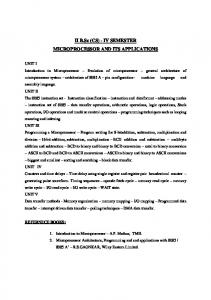
2.1.1 Parsing and Detector generator We have developcd a parser (using Unix's LEX and Y ACC tools) which is capable of parsing transition relation expressions that use the grammar described above, Given an event expression or a causal relation, the parser is capable of extracting the timing relationships between the constituent transitions as well as the d~ri~tion (in CUPL) of detectors ~apable of detecting the desc~bed events. At thl,S~Int, we are capable of generatIng detectors of even~ descnbed through assocla~ve op,erators. The sl;ructure of such detectors are !n ~e form of nonsequent~alloglc. The parser IS curren~ly expanded so th~t I! wIll be capable of generatIng detectors of events d:scnbed .by non-assoclatlve operators. Such detectors takc the form of sequential machInes. (Such detectors are for example needed to dctect a predcfincd sequcnce of transitions obeying well specified precedencetiming). Precedcnce extraction allows us to graphically display the transition relation expressions in the form of a trace plot, so that relation expressions can be visually vcrified by the user. An example is shown in Fig. 1. Furthermore, we can extract the relative minImax timings between two transitions. These data are used in the low-Ievel design of logic blocks. Note however, that often the timing between transitions is indeterminate or infinite, and extracting these unusable values may indicate incorrect design intentions or poorly-formed transition relation cxprcssions. 2.2 Control and Data Protocols At the second level of the representation, collections of limited numbers of causal relations describe basic control or data transfer protocols, using the description language. Examples of such protocols include the two signal handshaking protocol found in many information transfer subsystems. Handshake SIG1
Template
~
iZ:5===
componcnt
SIG2 handshake template ! ASSERTED SIG I -> ! ASSERTED S1G2 -> ! NEGATED
SIGl
->
! ASSERTED SIG2 @ TI ! NEGATED SIGl @ T2 ! NEGATED
SIG2 @ T3
DATA
---o---~
3. '>--
can initiate
a data
transfer
(e,g,
of an of
Functional
Block
Design
Level
The Functional Block design level considers pairs of components and identifies the various groups of signals that need to be interfaced. It generates "functional blocks" and idcntifies the correct signals which are used by these blocks. Each block represents a specific function, The function definition will be used at a later sk1geto refine design of the block, .Aspects of the Functional Block d~sign level reported in this work, Incorporate knowledgc ncccssary for the dcslgn of the data transfer portions of the interfa~e" It is capable of idcntifying th.eprotocol used for the data transfer, and accordIngly specifies the correct "functIonal blocks" for the control, address, and data groups of signals. As an example, we have used two specific components, namely an MC68000 processor and a MK6116 2K by 8 static RAM and had the corresponding blocks and participating signals identified in two experiments, the first in~olving a single processor and a single memory component, while the second Involvcd two mcmory components. .;: Bc h avlors, " th clr" a ddress. dala an d conlro I buses are From thc 'r d a I a- I ran.fjer bl k " " f th ' ddr ( 'd ' , I' dent "fied a d "b ff I I, n u er oc s Inter ace e respectIve a ess urn Irectlona I buffers) and data (bidircctional buffers) buses. Because the MC68000 has an asynchronous bus which is manif t d th h th h d hak" beh " ' es e roug e an s Ing avlor as an
DS I DATA TIMING (READ) ! ASSERTED LDS -> ! V ALIDI DO-D7 @ [--,(50+ T6)] ! NEGATED LDS -> ! INV ALlDI DO-D7 @ [0,20] ! ASSERTED UDS -> ! V ALIDI D8-D15 @ [--,(50 +T6)] ! NEGATED UDS -> ! INV ALIDI D8-D15 @ [0,20] In the above equation, T6 is DTACK assertcd delay from LDS/UDS signal in the LDS/UDS/DTACK timing.
th
behavior
this. component includes the two- signal handshaking protocol as well as separate gatIng protocols for the transfer of the addresses and data. These protocols correspond to the fact that the MC68000 uses an asynchronous non-multiplexed bus.
~ (
a mastcr
Thc example depicted in Fig. 2 represents the partial specification MC68000 component, The data transferring behavior READ-PROTOCOL-l
Another typical example is the gating protocol used for the actual transfer of data. The following is a template showing the timing of the LDS/UDS strobes and the data bus for the MC68000 microprocessor. DS
exhibiting
processor, DMA) whilc a modulc exhibiting a slave bchavior can only respond to data transfer requests (e.g. mcmory). A dala-lran.ifer Behavior involves three types of signals grouped into buses: the conlrol-bus, address-bus, and dala-bus. These groups are identified through the uses-conlrol-bus, uses-dala-bus, and uses-address-bus relations. The control and transfer protocols involved are identified through the has-liming and useslemplale relations-
2.3 Standard Behaviors .' ., " " At thc hlghcst levcl of thc rcprcscntatlon, collections of .IbasIc protocols as
S ey dexist d Bat
the' second level, constItute Standard Behaviors." In gcneral, a , " tan 3! ehavlor comprises two" ~ar~: th,e co!1trol p~t which d~scrlbes ~e behavIor of the .control s!gnals partlclp~tlng In ~IS behavior and the Information transfer part which descrlbcs the actual InformatIon transfer.
Examples of Standard Behaviors are data transfer behaviors such as the ones found in processors and which incorporate both a control protocol and the actual transfcr protocols neccssary for the dclivery of addresses and data on a bus, In contrast, the data transfcr behavior of static memory components are devoid of
4
the control protocol. This a~s.c~ceof ~ ~ontrol protocol illustrates the inability of a memory componcnt to Initiate actlvi~y. , .the Protocols as wcll as.Standard Behaviors are depIcted as semantiC networks (networks of schcmata In Knowledge Craft). Template networks of schemata
SFor examplc, the existcnce of a two signal handshaking behavior in a bus (e.g. MC68000 asynchronous bus), nccessitatcs the generation of an acknowledge signal within a certain delay. Once such a bchavior has bcen detcctcd, it is easy to synthesize the appropriate block that will gcnerate the required acknowledge.
A particular example of such a bchavior pattern can be considered is the two signal handshaking protocol and its variants which is widely used for data transfer operations.
2
i~tance of a handshake tcmplate, a "delay selection" block is created which will .from the appropriate data transfer acknowledge ( DTACK ), and chip
generate
selection ( CE"" ). The following shows the resulting delay block for DTACK : II BINARY-BLOCK.3 INSTANCE: BINARY-BLOCK PURPOSE: DATA- TRANSFER CONTROL GENERATE TYPE: DELAY DETECT: (MC68000 TIMING-1 EVENT1) GENERATE: (MC68000 TIMING-1 TRANSITION2) DELAY: (MAX ((DELTA (MIN MK6116 TIMING-6 EVENT1 TIMING. 6 TRANSITION2 TIMING-6 EVENT1)) MINUS ) DEVICE1: U1 DEVICE2: U2 EXTRA- TIMING1: TIMING-7 EXTRA- TIMING2: NIL }) ..with The necessary "significant" events are extracted from the descriptIon of the control and transfer protocols and the corresponding event detectors are g~nerated automatically. Fig. I depicts the description of such an event .(~IS eve~t identifies the onset of a memory access cycle in the MC68000, and It IS used In the generation of the appropriate data transfer acknowledge DT ACK and the .MC68000 correspondIng detector. .in 4. Knowledge and Rule Representatton We have used Knowledge Craft and OPS-CRL to represent the know.led~e necessary for the functional block design level. The cluster of .rul~s w~lch IS capable of pcrforming the data transfer design comp~~es ~Ies.whlch IdentIfy th.e address, data and control buses, the signals participatIng In them and their behaviors, and rulcs to structure the appropriate "functional blocks". .level. A typical rule for connecting the control bus of two components together IS shown below: (p create-control.block (timing "schema-name "uses-template handshake-template) (data.transfer-control.bus "schema-name "has.timing (member