March 24, 2015
13:47
IJMPB
S0217979215400081
Int. J. Mod. Phys. B Downloaded from www.worldscientific.com by UNIVERSITY OF AUCKLAND LIBRARY - SERIALS UNIT on 03/30/15. For personal use only.
International Journal of Modern Physics B Vol. 29 (2015) 1540008 (7 pages) c World Scientific Publishing Company
DOI: 10.1142/S0217979215400081
Microstructure and properties of Ni Co TiO2 composite coatings fabricated by electroplating Yuxin Wang∗ , Xin Shu and Wei Gao† Department of Chemicals and Materials Engineering, The University of Auckland, PB 92019, Auckland, New Zealand ∗
[email protected] †
[email protected] R. A. Shakoor‡ and Ramazan Kahraman§ Department of Chemical Engineering, College of Engineering, Qatar University, PB 2713, Doha, Qatar ‡
[email protected] §
[email protected] Pengfei Yan, Wei Lu and Biao Yan School of Materials Science and Engineering, Tongji University, 200092, Shanghai, P. R. China Received 17 September 2014 Revised 13 January 2015 Accepted 14 January 2015 Published 24 March 2015 Ni–Co coatings are widely used due to their unique mechanical properties, high anticorrosion properties, good thermal stability and special magnetic properties. Ni–Co–xTiO2 (x = 0–20 g/L in the electrolyte) composite coatings were fabricated by electrodeposition on mild steel. The effect of TiO2 concentration on the microhardness, surface morphology and tribological behaviour has been studied. The results show that, comparing with pure Ni–Co coating, both microhardness and wear property of the Ni–Co–TiO2 composite coatings were significantly improved. The microstructure and properties for the Ni–Co–TiO2 composite coatings were varied following with the TiO2 concentration. The mechanism of mechanical property improvement was also discussed. Keywords: Ni–Co coatings, electrodeposition, composite coatings.
1. Introduction Ni–Co coatings have been investigated for several decades due to their unique properties, such as high strength, good wear resistance, favorable corrosion resistance and special magnetic properties. Ni–Co coatings have been widely used as recording head materials in computer hard drive and other electronic devices. These coatings 1540008-1
page 1
March 24, 2015
13:47
IJMPB
S0217979215400081
Int. J. Mod. Phys. B Downloaded from www.worldscientific.com by UNIVERSITY OF AUCKLAND LIBRARY - SERIALS UNIT on 03/30/15. For personal use only.
Y. Wang et al.
can be fabricated by either electroplating or electroless plating.1 – 6 Compared with the electroless plating which needs to conduct under a strictly control process, electroplating is easier to operate and the deposition rate can be accurately controlled. Ni–Co coatings have been electrodeposited from a variety of simple and complex baths by utilizing direct current or pulse current.7 – 9 There are extensive studies on the Ni–Co electrodeposited coatings for magnetic applications especially in microelectronic technology. The effect of Co content on the properties of coatings has been systematically investigated. Recently, much effort has been devoted to fabricating composite coatings in order to increase the properties of Ni–Co coatings. Various solid particles, such as SiC,10 CeO2 ,11 Al2 O3 (Ref. 12) and WC,13 have been incorporated into the Ni– Co coating matrix through electrochemical methods. However, limited research has been so far reported on the preparation and property of electrodeposited Ni–Co– TiO2 composite coatings,14,15 and the existing research focused on the corrosion property of composite coatings. In the present work, Ni–Co–TiO2 composite coatings were prepared by electroplating utilizing a Ni–Co plating bath containing TiO2 nanoparticles. The effect of TiO2 nanoparticles concentration on the microstructure and properties of coatings were systematically investigated. 2. Experimental Details Both Ni–Co and Ni–Co–TiO2 composite coatings were electroplated onto the mild steel substrate (20 × 30 × 1 mm3 ). The steel substrates were mechanically polished using SiC paper to a grit of #1200, then degreased ultrasonically in ethanol. Before electroplating, the specimens were pre-treated in 1 mol/L HCl solution for 2 min at room temperature. The bath was prepared using Sigma analytical grade reagents and contained: nickel sulfate hexahydrate, 250 g/L; nickel chloride hexahydrate, 40 g/L; boric acid, 35 g/L; cobalt sulphate, 30 g/L. In order to achieve a good particle dispersion, nanometer sized TiO2 powders with a mean diameter of < 25 nm (Sigma–Aldrich, Auckland, New Zealand) were added into the bath solution and then vibrated by using an ultrasonic wave before conducting electroplating. Five concentrations of TiO2 nanopowders from 0 to 20 g/L were used in the plating electrolyte. For easy description, Ni–Co–x g/L TiO2 is used to represent the coatings containing different TiO2 . During the experiment, the pH value of bath was adjusted at 3.5 and the temperature was maintained at 55◦ . The agitation speed was set to 400 rpm. Every sample was plated for 20 min under the current density of 20 mA/cm2 . The phase structure of the coatings was determined by the X-ray diffraction (XRD) patterns using a Bruker D2 Phaser diffractometer operated at 30 kV and 10 mA with the Cu Kα radiation (λ = 0.15406 nm). The cross-section microstructure of Ni–Co–TiO2 composite coatings was analyzed using a FEI Quanta 200 field emission scanning electron microscope. A MiniPal 2 PW4025 X-ray spectrometer (XRF) with rhodium tube and spinner was used for composition analysis. 1540008-2
page 2
March 24, 2015
13:47
IJMPB
S0217979215400081
Int. J. Mod. Phys. B Downloaded from www.worldscientific.com by UNIVERSITY OF AUCKLAND LIBRARY - SERIALS UNIT on 03/30/15. For personal use only.
Microstructure and properties of Ni–Co–TiO2 composite coatings
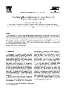
The microhardness of coatings was measured using a Vickers hardness tester under a load of 50 g with a holding time of 15 s. The results for the hardness were the average of 10 measurements. The wear tests of coatings were carried out in a micro-tribometer (Nanovea, USA) in air at 25◦ C and relative humidity of ∼ 50% under nonlubricated conditions. All wear tests were performed under a load of 5 N with a sliding distance of 40 m. A ceramic ball was used as the counter surface and the sample was tested linearly at a disk speed of 100 rpm. The width of the wear track was measured using optical a microscope. The volume loss was then calculated from the wear track width. Electrochemical measurements were conducted at room temperature in the nonaerated 3.5 wt.% NaCl solution using CHI 660 electrochemical workstation. All tests were performed in a standard flat cell with three-electrode system: a saturated calomel electrode (SCE) as the reference electrode, a Pt electrode and a coated specimen as the working electrode. Potentiodynamic polarization curves were plotted at a scan rate of 1 mV/s. The exposed surface area of samples was 1 cm2 . 3. Results and Discussion 3.1. Microstructure and cross-section image of coatings XRD patterns of electroplated Ni–Co coatings as a function of TiO2 powder concentration are shown in Fig. 1. As can be seen, all coatings have a similar face-centered cubic (FCC) lattice structure with preferential (111) growth orientation. Beside (111) plane, Ni (200) and (220) planes can also be seen. In addition, the weak peaks at 25.3◦ of composite coatings can be assigned to (101) plane of anatase, indicating that the TiO2 nanoparticle was embedded in the coatings.
Fig. 1.
XRD spectra of Ni–Co–TiO2 composite coatings. 1540008-3
page 3
March 24, 2015
13:47
IJMPB
S0217979215400081
Int. J. Mod. Phys. B Downloaded from www.worldscientific.com by UNIVERSITY OF AUCKLAND LIBRARY - SERIALS UNIT on 03/30/15. For personal use only.
Y. Wang et al.
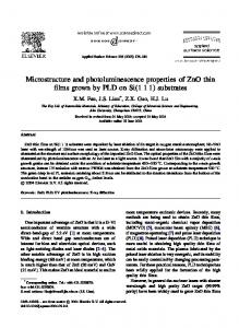
Fig. 2.
Cross-section image: (a) Ni–Co and (b) Ni–Co–10 g/L TiO2 composite coating.
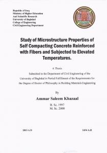
The coating thickness and cross-section microstructure were investigated by SEM analysis as shown in Fig. 2. Both Ni–Co and Ni–Co-10 g/L TiO2 composite coating show a uniform coating thickness around 8 µm. For Ni–Co-10 g/L TiO2 composite coating, TiO2 particles can be clearly seen in the cross-section of coating due to the agglomeration of TiO2 nanoparticles. 3.2. Mechanical properties of coatings The effects of TiO2 powder concentration on Ti content in the coatings and their microhardness are shown in Fig. 3. The Ti content increased gradually with increasing TiO2 powder addition. Ti content was increased to 0.45% when the TiO2 powder concentration is 20 g/L. The microhardness of Ni–Co coating is ∼ 651 HV50 . At low powder concentration, the microhardness of Ni–Co–TiO2 composite coating increased significantly with increasing TiO2 content. The microhardness reached up to
Fig. 3. Effect of TiO2 concentration on microhardness and Ti content of Ni–Co–TiO2 composite coating. 1540008-4
page 4
March 24, 2015
13:47
IJMPB
S0217979215400081
Int. J. Mod. Phys. B Downloaded from www.worldscientific.com by UNIVERSITY OF AUCKLAND LIBRARY - SERIALS UNIT on 03/30/15. For personal use only.
Microstructure and properties of Ni–Co–TiO2 composite coatings
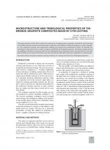
Fig. 4.
Wear track images: (a) Ni–Co, (b) Ni–Co-10 g/L TiO2 and (c) Ni–Co-20 g/L TiO2 .
Fig. 5.
Wear volume loss: (a) Ni–Co, (b) Ni–Co-10 g/L TiO2 and (c) Ni–Co-20 g/L TiO2 .
the optimum value, ∼ 747 HV50 , when the powder concentration is 10 g/L. Further increasing TiO2 concentration led to a decrease of microhardness to ∼ 680 HV50 , which is still higher than Ni–Co coating. Figure 4 shows the wear track images of coatings after testing. The volume removed from the coatings was calculated from the wear track width as shown in Fig. 5. The wear properties of coatings show the same tendency with the microhardness. The Ni–Co coating has the widest wear track width of ∼ 409 µm and the largest wear volume loss of ∼ 4.59 × 10⁻¹³ m3 due to the low hardness. After adding the TiO2 nanoparticles, the wear track width became narrower and the wear volume loss was smaller. The 10 g/L TiO2 nanoparticle enhanced Ni–Co– TiO2 composite coating possesses the best wear resistance, giving the volume loss of ∼ 2.27 × 10⁻¹³ m3 . Further increasing the TiO2 concentration, however, led to an increase of wear volume loss to ∼ 3.56 × 10⁻¹³ m3 . The experimental results prove that the main factor which determines the mechanical properties of coatings is the TiO2 addition. The strengthening mechanism can be mainly attributed to the nanoparticles dispersion hardening. The nano-particles distributed in the coating matrix play a role as the second phase to restrict the motion of dislocations and increase the resistance to deformation, 1540008-5
page 5
March 24, 2015
13:47
IJMPB
S0217979215400081
Int. J. Mod. Phys. B Downloaded from www.worldscientific.com by UNIVERSITY OF AUCKLAND LIBRARY - SERIALS UNIT on 03/30/15. For personal use only.
Y. Wang et al.
resulting in the dispersion strengthening effect. However, nanoparticles tend to agglomerate due to their large surface energy when excessive TiO2 nanoparticles were added. A porous microstructure will form in the coating matrix, resulting in deterioration of mechanical properties. As for the wear properties, the improvement of wear resistance could be mainly attributed to the improved hardness and the incorporated TiO2 nanoparticles. The hard TiO2 nanoparticles embedded in the coatings can reduce the direct contact between Ni–Co matrix and abrasive surface. These nanoparticles also played the role of solid lubricant during the wear process. However, too many TiO2 nanoparticles cause a porous structure, resulting in the decline of wear resistance.
3.3. Corrosion properties of coatings The potentiodynamic polarization curves for Ni and Ni–Co–TiO2 composite coatings are shown in Fig. 6. While the Ni coating has the lowest corrosion current density and highest corrosion potential, Ni–Co coating shows the highest corrosion current density and lowest corrosion potential. The corrosion potential was shifted to the positive direction and the corrosion current density was decreased by adding the TiO2 nanopowder up to 10 g/L in the Ni–Co electroplating solution, indicating an improvement of corrosion resistance for the Ni–Co–TiO2 composite coatings. The improvement could be mainly attributed to the uniform distribution of TiO2 nanoparticles in the Ni–Co matrix, probably reduce the corrosion rate on the coating surface.16 However, consistent with the results of mechanical properties, more TiO2 nanopowder addition will cause a slight deterioration of corrosion resistance for the coatings due to the porous microstructure. The corrosion resistance of Ni– Co-20 g/L TiO2 composite coating is worse than Ni–Co-10 g/L TiO2 coating but still better than the Ni–Co coating.
Fig. 6.
Potentiodynamic polarization curves of Ni and Ni–Co–TiO2 composite coatings. 1540008-6
page 6
March 24, 2015
13:47
IJMPB
S0217979215400081
Microstructure and properties of Ni–Co–TiO2 composite coatings
Int. J. Mod. Phys. B Downloaded from www.worldscientific.com by UNIVERSITY OF AUCKLAND LIBRARY - SERIALS UNIT on 03/30/15. For personal use only.
4. Conclusion Ni–Co–TiO2 composite coatings were produced by electrodeposition method. Their microstructure, mechanical properties and corrosion resistance were systematically studied. The incorporation of TiO2 nanoparticles provides a significant second phase dispersion strengthening effect. The mechanical properties and corrosion properties of electroplated Ni–Co–TiO2 coatings reach the optimum values when the TiO2 concentration is 10 g/L. Excessive addition of TiO2 nanoparticles leads to a deterioration of strengthening effect and corrosion resistance due to the formation of porous structure. The microstructure, mechanical and corrosion properties of the Ni–Co–TiO2 coatings are strongly affected by the amount of TiO2 particles addition. Further investigation is being conducted for the industrial applications. Acknowledgments This paper was sponsored by NPRP Grant NPRP-4-662-2-249 from the Qatar National Research Fund (a member of Qatar Foundation). The related research was also supported by a New Zealand Marsden Grant and an Auckland UniServices project. Xin Shu is supported by the China Scholarship Council (CSC). The authors want to express our gratitude to Glen Slater, Chris Goode and technical stuff in Rigg Electroplating Ltd, New Zealand. References 1. 2. 3. 4. 5. 6. 7. 8. 9. 10. 11. 12. 13. 14. 15. 16.
M. Srivastava et al., Surf. Coat. Technol. 201, 3051 (2006). L. Qin, J. Lian and Q. Jiang, J. Alloys. Compd. 504, S439 (2010). C. Lupi et al., Surf. Coat. Technol. 205, 5394 (2011). B. Bakhit and A. Akbari, J. Alloys. Compd. 10, 285 (2013). L. Tian, J. Xu and S. Xiao, Vacuum. 86, 27 (2011). S. Hassani, K. Raeissi and M. A. Golozar, J. Appl. Electrochem. 38, 689 (2008). R. Karslioglu et al., Acta Phys. Pol. A. 123, 424 (2013). B. Tury et al., Surf. Coat. Technol. 202, 331 (2007). L. M. Chang, M. Z. An and S. Y. Shi, Mater. Chem. Phys. 94, 125 (2005). Y. Yang and Y. F. Cheng, Electrochim. Acta 109, 638 (2013). M. Srivastava, V. K. W. Grips and K. S. Rajam, Appl. Surf. Sci. 257, 717 (2010). L. M. Chang, H. F. Guo and M. Z. An, Mater. Lett. 62, 3313 (2008). A. Amadeh and R. Ebadpour, J. Nanosci. Nanotechnol. 13, 1360 (2013). Y. Dai et al., Met. Finish. 89, 162 (2011). B. Ranjith and G. P. Kalaignan, Appl. Surf. Sci. 257, 42 (2010). R. A. Shakoor et al., Mater. Des. 59, 421 (2014).
1540008-7
page 7