Microstructure Characterization Using X-ray Computed Tomography ...
Recommend Documents
[4, 5] Steaming and subsequent catalyst regeneration of FCC catalyst particles is performed after each cracking phase to combat reversible deactivation effects, ...
pore size distribution (PSD), and pore connectivity can be deduced ... The beamline get photons ..... Again, to make more meaningful comparison, accessible.
tomography for early detection of non-small cell lung cancer ... Institute of Clinical Radiology and Nuclear Medicine, University Medical ... hemithorax and usually presents with nodules involving ..... symptoms and clinical findings (10,36).
Kumar V, Abbas AK, Fausto N, Mitchell R. Robbins basic pathology. 8th ed. Philadelphia: Saunders Elsevier, 2007, p516-22. 2. Horsburgh CR Jr. Priorities for ...
2 Computer Science Department, Institute of Bialystok, Poland. 3 Service d'hémodynamique et .... acquired on a Siemens Somatom volume zoom 4 detectors.
2 Computer Science Department, Institute of Bialystok, Poland. 3 Service d'hémodynamique et .... acquired on a Siemens Somatom volume zoom 4 detectors.
However, A third generation CT scanner is particularly vulnerable to ring artefacts because the same physical .... Use bow tie filter. (Only Alternative, appropriate.
studies of the medicinal fungus Hericium coralloides. Johannes D. Pallua1,2. Institute of Legal Medicine, Medical University of. Innsbruck, MüllerstraÃe 44, 6020 ...
Nov 3, 2016 - laboratory-scale X-ray CT technology and image segmentation techniques [27,28], ..... sifting of PSD below this size indicate particle crushing ...
The Cram`erâRao (CR) lower bound is used to analyze estimation errors for different boundary shapes. Under a spatially inhomoge- neous Gibbs field model for ...
Feb 27, 2016 - Oakland University William Beaumont School of Medicine 2. ..... 6. Tong HC, Carson JT Jr, Haig AJ, Quint DJ, Choksi VR, Yamakawa KS: Magnetic resonance ... Weishaupt D, Zanetti M, Hodler J, Boos N: MR imaging of the ...
The basic method is the Kaczmarz equation [7] shown in equa- tion (2). When referring to ART, this algorithm is usually assumed. While very effective, variations ...
Feb 27, 2016 -
Sep 7, 2015 - A novel approach to proton CT reconstruction using backprojection-then- filtering (BPF) is proposed. A list-mode algorithm is formulated ...
of custom software (âROBUSTâ) developed using C ..... biopsy. The main advantage of using an optical tracking system ... Another disadvantage lies in the low.
The first results of three-dimensional grain mapping using a laboratory tomograph equipped with a microfocus W target X-ray tube source, operated at 90kV and ...
lographic orientations from a titanium sample containing 42 grains is ... Perspectives are given for the further development of the technique ..... Application.
XCounter AB has developed a photon-counting gaseous avalanche detector with
no ...... The whole construction is mounted on a metal plate ... Figure 19:
Schematic of the rotating object container from the side (left) and from above (
right).
Department of Conservative Dentistry, King's College London Dental Institute, London, UK .... A custom sample holder was built to ... and measured using Microview software (GE). ..... Craniofacial Development, King's College London Den-.
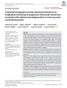
The global computed tomography market was valued at $4,894.3 million in 2015, and it is expected to grow at a CAGR of 5.0% during 2016-2022. Based on slice type, the high slice type segment is expected to witness the faster growth, CAGR of 5.3%, duri
IMAGING IN HOOFED MAMMALS' DISTAL LIMB ... variety of captive hoofed mammals. ... Seventy nine captive wild odd-toed ungulates (Perissodactyla) and ...
Jul 15, 2018 - The neuronal ceroid lipofuscinoses (NCLs, Batten disease) are a ..... tinkercad.com/things/5Y1f9AKrEiAâsheepâbrainâcavityâ19mthâbatâ.
neck of pancreas, just above the Gerota fascia with en ... Gerota fascia (anterior RAMPS). When the ..... Gavazzi F, Zerbi A, Di Carlo V. Indications for surgery and.
lesions [renal cell carcinoma (Ca) =16, chromophobe renal cell Ca =2, squamous cell Ca =1, urothelial ... modalities such as ultrasound, computed tomography.
Microstructure Characterization Using X-ray Computed Tomography ...
X-ray CT is a nondestructive technique used for materials microstructure
characterization. ➢ The scan procedure is as follows: » A source transmits X-rays
with ...
Microstructure Characterization Using X-ray Computed Tomography
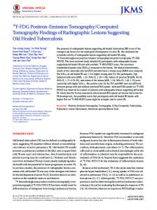
Description of X-ray CT
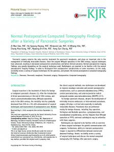
¾ X-ray CT is a nondestructive technique used for materials microstructure characterization ¾ The scan procedure is as follows: » A source transmits X-rays with certain intensity » Part of the radiation gets absorbed, part gets scattered, and the rest penetrate through the specimen » The intensity of the transmitted X-rays are measured by the X-ray detector » The specimen rotates 360 to transmit rays from all possible directions » The linear attenuation coefficients (μ), which are a property of the material, are used to estimate the different phases of the specimen and to construct the images: I = I o exp ∫ − μ (x , y ) ds ray
1
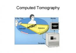
X-ray CT Process
Tomography
Image processing
2-D images
2-D analysis
3-D analysis
X-ray CT Equipment ¾ The X-Tek X-ray Core Scanner offers both microfocusCT and high power mini-CT within the same cabinet system. ¾ By utilising the precision manipulator to move the sample between two adjacent beam lines the system provides an intuitive method of interchanging between microfocus-CT and mini-CT. ¾ The system is capable of taking microfocus data up to 225kV and scatter free data (at resolutions up to 200mm/pixel) up to 350kV on denser samples.
Metal/Ceramic 350/0.5 Tungsten 600W 0.5mm to EN 122543 Closed Loop air-oil
» Source 2: X-Tek 225 kV Micro-focus X-Ray Source X-ray tube: Fitted with 225-Watt air cooled target Voltage: 20 to 225kV Beam current: 0 to 2mA max Power: 225W Focal spot size: 3 - 5μm
X-ray CT Equipment ¾ CT Manipulator specification – 350kV cabinet » The system is fitted with a high precision 5-axis manipulator with the following specifications: 9 Precision stepper motor driven ball screws with joy-stick and CNC control Options capable of 10000:1 speed variation 9 X,Y,Z axis travel 600mm (0.0025mm to 25mm/sec) 9 Rotate axis – continuous rotation stage (72 degrees/sec to 8.3x10⁻⁴ degrees/sec) 9 Max loading capacity 25kg 9 Precision over whole scan area better than +/- 0.2mm
AREA – for Cone beam CT Industrial 6 inch X-ray image intensifier Low burn scintillator (Caesium Iodide) Non-browning glass 10bit digitisation with OCI (on Chip Integration) 768 x 572 pixel CCD camera
» Imaging System 2: High Energy, Scatter Free X-ray detector for mini-CT Detector type: LINEAR – for CT geometry and scatter rejection Detector length: 307mm Pixel size: 200mm x 200mm, binning X2, X4, X8 Dynamic Range: 12 bit, 4096 grey scales 350kV radiation protection / collimation
Applications
5
Analysis of Air Void Distribution Thresholded Image to identify the amount and size of air voids
Grayscale image resulting from image processing
N
n=
14%
Statistical analysis of air voids
Percent Air Voids (%)
12% 10% 8%
∑ i =1
( Av )i AT N
Three dimensional air void structure
6% 4% 2% 0% Minimum
1st Quartile
Median
F (t ) = 1 − e
3rd Maximum Average Quartile
( θ )β
− t
,
t>0
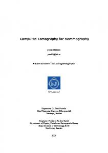
Analysis of Connectivity and Air Void Flow Paths
k=
0.80
0.60
u c
0.40
0.20
3
2
2
0.00 0.00
Damage decreases
γ c.T .S μ n
1.00
N /N Nc/N u
¾ A method was developed for the analysis of air void connectivity and flow paths. ¾ This method was used to relate air void structure to permeability and moisture damage.
0.20
2
= 0.91 R2R=0.91
0.40
0.60
0.80
1.00
1.20
1.40
1.60
1.80
average diameter (mm) Average Diameter E(x)
6
Simulation of Fluid Flow and Permeability ¾ Input: » X-ray CT image » Microstructure dimensions » Fluid properties
¾ Output: » Flow fields » Permeability directional distribution
Measurements of Moisture Transport ¾ An experimental setup using X-ray CT was used to: » Monitor water transport in asphalt mix » Calculate capillary rise » Estimate the capillary contact angle of the asphalt mix
Saturated specimen during X-ray CT scanning
Three dimensional view of the air voids filled with water due to capillary action after different soaking periods
7
Discrete Element Analysis of Asphalt Mix Microstructure
Forensic Evaluation of Compaction Percent Air Voids (%) 0%
Three-Dimensional Distribution of Aggregates Due to Compaction and Loading The aggregate distribution is included in a mechanistic model for predicting asphalt pavement performance L30B