ORIGINAL ARTICLE
Robot-Assisted Biopsy Using Computed Tomography-Guidance Initial Results From In Vitro Tests Joachim Kettenbach, MD,* Gernot Kronreif, PhD,† Michael Figl, PhD,‡ Martin Fu¨rst, MS,† Wolfgang Birkfellner, PhD,‡ Rudolf Hanel, PhD,‡ Wolfgang Ptacek, BS,† and Helmar Bergmann, PhD‡
Purpose: We sought to develop a robotic system for computed tomography (CT)-guided biopsy to validate the feasibility, accuracy, and efficacy of the system using phantom tests. Materials and Methods: Ten peas (mean diameter 9.9 ⫾ 0.4 mm) embedded within a gel phantom were selected for biopsy. Once the best access was defined on CT images, the position of the phantom was recorded by an optical tracking system. Positional data about the phantom and the corresponding CT image was transferred to the robot planning system (Linux-based industrial PC equipped with video capture card). Once the appropriate position, angulation, and pitch were calculated, the robotic arm moved automatically with 7 degrees-of-freedom to the planned insertion path, aiming the needletrajectory at the center of the target. Then, the biopsy was performed manually using a coaxial technique. The length of all harvested specimens was measured and short cut pieces of a guidewire were pushed into the target to evaluate the deviation of the actual needle track from the target. Results: In all targets, biopsy specimens (mean length 5.6 ⫾ 1.4 mm) were harvested with only 1 needle pass required. The mean deviation of the needle tip from the center of the target in the x and z axes was 1.2 ⫾ 0.9 mm and 0.6 ⫾ 0.4 mm, respectively. Conclusions: Robotic-assisted biopsies in vitro, using CT guidance, were feasible and provided high accuracy.
Received August 28, 2004 and accepted for publication, after revision, December 16, 2004. From the * Department of Radiology, Medical University Vienna, General Hospital, Vienna; †Robotics Laboratory, ARC Seibersdorf Research, Seibersdorf; and ‡Center for Biomedical Engineering and Physics, Medical University Vienna, General Hospital, Vienna, Austria. The development of the robotic system was co-funded by the Austrian Federal Ministry of Transport, Innovation and Technology (BMVIT). Supported in part by the Ludwig-Boltzmann Institute (Director: C. Herold) for Clinical and Experimental Radiology. Reprints: Joachim Kettenbach, MD, Division of Angiography and Interventional Radiology, Department of Radiology, Medical University Vienna, General Hospital, Waehringer Guertel 18-20, A-1090 Vienna, Austria. E-mail:
[email protected]. Copyright © 2005 by Lippincott Williams & Wilkins ISSN: 0020-9996/05/4004-0219
Investigative Radiology • Volume 40, Number 4, April 2005
Key Words: medical robotics, interventional radiology, surgical robotics, biopsies, computed tomography (CT) (Invest Radiol 2005;40: 219 –228)
P
ercutaneous biopsy performed under the guidance of computed tomography (CT) has been shown to be a safe and reliable alternative to excisional surgical biopsy. The high efficacy of this technique, however, depends on the accuracy of needle placement and the quality of the harvested tissue. At times, access to a target can be technically challenging because of various factors, including limited space at the skin entry site or a difficult angulated access. Thus, a robotic-assisted biopsy device using the guidance of CT is of great clinical value for several reasons: (1) it will provide very stable needle guidance, even for angulated approaches,1–3 (2) it will allow access to lesions when the width of the CT gantry would limit the access for a biopsy needle or other interventional tools, such as thermal ablation probes, and (3) it may further expand the time window for exploration of a lesion when using contrast agents because more time can be spent to target a lesion. Then, the robot may be able to guide the needle into the most promising region of the lesion without the need for a second contrast injection.4 Thus, more efficacious characterization and treatment, particularly for lesions that are difficult to target, can be anticipated. Several groups have already used CT imaging to guide roboticassisted procedures.3,5– 8 To our knowledge, however, none of these systems was designed to use both imaging modalities, ultrasonography (US) and CT. Our goal was to develop a prototype robotic system (B-Rob I) designed to be used for US- and CT-guided biopsies. We have recently reported our results of successful in vitro biopsies using US guidance.9 In this study, we used CT guidance and sought to prove the feasibility, accuracy,
219
Kettenbach et al
and efficacy of B-Rob I, a robotic system, during robotassisted biopsy, validated by in vitro phantom tests.
MATERIALS AND METHODS The complete robotic system, B-Rob I, includes the following components: (1) an optical tracking system (Polaris, Northern Digital Inc., Waterloo, Ontario, Canada) for continuous update of positional data of the CT scanner, the CT table (ie, the phantom bag’s position), and the robot position; (2) a Linux (SUSE 7.1)-based industrial PC (Pentium III, 1 GHz, 128 MB RAM) equipped with a video capture card (WinTV-PCI-FM 718, Hauppauge Computer Works Inc.), including the medical planning software “ROBUST”; (3) a 4-degree of freedom (DOF) robotic arm for gross positioning; (4) a 3-DOF needle-positioning unit (NPU), including a needle holder; and (5) the robot control system (MS Windows 2000-based industrial PC, Pentium III, 1 GHz, 128 MB RAM), which includes custom input devices and safety switches to control the robot kinematics. According to the requirements of clinical practice, the entire robotic system was mounted on a mobile platform. Thus, the robotic system could easily be transferred to different interventional sites. Because the video output is a standardized interface of US scanners and can be used to connect to CT displays easily, we used the video signal as input for the robot system.
Robot Design As described previously, the robotic system consists of a 4-DOF robotic arm that uses 3 linear axes (A1-A3) and one rotational axis (A4) for gross positioning (Figs. 1 and 2) of the NPU. At the end of the robotic arm, the 3-DOF NPU is mounted for fine positioning, (Fig. 2B). The NPU itself
Investigative Radiology • Volume 40, Number 4, April 2005
consists of 2 parallel “fingers” made from carbon fiber composite material connected to each other with spherical joints and a cylindrical needle holder in between. Relative movements of the resulting parallelogram kinematics provide fine orientation of the needle holder. This design enables the needle holder axis to angulate 15° in the 4 main directions (Fig. 2B and C). A third linear DOF drive serves to move the NPU to the patient’s skin (ie, phantom surface). Thus, fine needle adjustments are possible with 3 DOF without simultaneous movement of the 4 main axes (A1–A4), which ultimately contributes to system safety. For easy sterilization, the 2 fingers, including the cylindrical needle holder, can be disconnected from the NPU by means of a rapid-change bayonet connection.
Registration of the System Components To determine the spatial relationship between the 3 involved system components (CT, phantom bag, and robot), the positional data of each item was obtained by 3 optical tracker tools (tracker A, B, and C) that were registered to the robot’s coordinate system (Fig. 2A).
Calibration of the Robot System In the first step, a rigid body transformation between a Perspex calibration tool attached to the carbon finger of the NPU and a tracker tool (labeled “tracker B”) had to be defined by means of a point-to-point registration process.10 In short, the registration algorithm defines a mathematical transform conveying the position of the calibration tool as measured in the tracker’s coordinate system to the robot coordinate system. The result of this registration procedure is a 4 ⫻ 4 matrix that allows for calculation of the needle position and angulation in the tracker coordinate system during the intervention using the robot’s internal position sensors (Table 1). During the first preclinical tests, the resulting fiducial registration error (—a measure of the accuracy of the registration procedure) was between 0.7 and 0.9 mm.11 It should be noted that the registration between the external position sensing system (the optical tracker) and the internal coordinate system of the robot is a procedure that has to be performed only once. During routine use, reregistration is not necessary provided that the mechanical connection of the optical tracker attached to the robot is stable.
Registration of CT Coordinates to the Robot
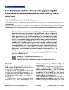
FIGURE 1. Kinematic structure of the robot for CT-guided interventions. The robot, as well as the user-interface and input devices, are located along the CT table.
220
To transfer the spatial coordinates of the needle, as measured by the robot during the intervention, to the coordinate system of the patient, the transformation between the robot coordinate system and the CT scanner coordinate system must be determined. The registration of the CT scanner results in a rigid transformation of 2D-CT-slice coordinates and slice location into the 3D coordinates of the robot (Table 1). The registration procedure we implemented was originally based on a method described by Detmer et al.12 For the © 2005 Lippincott Williams & Wilkins
Investigative Radiology • Volume 40, Number 4, April 2005
Robot-Assisted Biopsy Using CT-Guidance
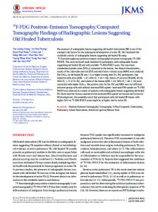
FIGURE 2. A, The gel phantom with the robot arm located within the CT gantry; the main axes (A1–A4) are used for gross positioning (closed white arrows). Black arrows point to the 3 optical tracking tools that were mounted at the CT gantry (tracker A), at the NPU (tracker B), and at the phantom box (ie, CT table; tracker C). The robotic interface for planning and monitoring of the biopsy process (lower right image) with the current needle trajectory is superimposed on the “grabbed” CT scan (open white arrow). The robot-input device (white star) is used in case manual correction of the robot movement is required. B, Detailed view of the needle positioning unit with the sagittal axis (ie, z-axis) A5, transversal axis A6, and vertical axis A7. For fine positioning, the 17-gauge puncture needle is inserted into the carbon needle guide. According to the calculated depth, using a marker at the needle shaft and a rubber ring, the 18-gauge biopsy needle (not shown) is inserted coaxially and the biopsy is performed manually using an automated biopsy device. C, Detailed view of the phantom within the gantry and the puncture needle inserted into the needle positioning unit mounted at the long axis, A4. An optical tracking tool is attached to the needle-positioning unit (arrow).
TABLE 1. Flowchart of the Registration Procedure
The calibration procedure of the robot to its internal coordinate system (shown on the left) is performed once and for all. The registration of the robot’s coordinate system to the CT scanner (shown on the right) is done before the intervention. DRF, dynamic reference frame; FRE, fiducial registration error; NPU, needle positioning unit; SVD, singular value decomposition.
© 2005 Lippincott Williams & Wilkins
221
Kettenbach et al
registration process, one tracker tool (tracker A) was firmly attached to the CT gantry as a reference frame and to establish a spatial relationship between the CT scanner and the robot in case of robot movements (Fig. 2A). Another tracking tool (tracker C) was attached to an acrylic glass (Perspex) cube, of which the position and orientation in space was defined with a registration process previously. The Perspex cube itself includes a Perspex frame with 6 nylon strings, and each string has 2 or 3 plastic fiducials (spheres with a 1 mm diameter) attached. A spiral CT data set of the phantom (120 kV, 160 mAs, rotation time 0.5 seconds, slice collimation 16 ⫻ 0.75 mm, slice width 12.0 mm, field-of-view (FOV) 300 mm, Kernel B30f) was acquired using a multisclice helical CT scanner (Somatom Sensation 16, Siemens Erlangen, Germany) equipped with an in-room LCD monitor. For the calibration procedure, the current image of all strings and their fiducials seen on the CT display was “grabbed” from the video output of the CT scanner and converted into a digital file using a Linux-based industrial PC equipped with a commercial video capture card (WinTV, Hauppauge Computer Works). At the same time the positional data of the CT table, as obtained by the optical tracker (tracker C), was transferred to the workstation. Then, each fiducial marker was identified by selection at the graphical user interface of the calibration system and combined with the known sphere’s coordinates. After selection of 20 –30 spheres, the calibration calculated a 6-DOF transformation matrix using the method of singular value decomposition. A detailed discussion of the implemented procedure is also given in.13
Investigative Radiology • Volume 40, Number 4, April 2005
Simultaneously, the corresponding image of the target was “grabbed” from the video output of the CT scanner and converted into a digital file. At the same time point, the coordinates of the CT table position were measured by the optical tracking system and transferred to the planning workstation (Fig. 2C).
Planning of the Intervention Planning of the intervention was performed by means of custom software (“ROBUST”) developed using C⫹⫹ programming language with Qt-Library (1.45) and SUSELinux 7.1. Using the acquired CT image, the “skin” entry point, as well as the center of the target, were selected on the planning workstation (Figs. 3 and 4A). After computation of the trajectory, relevant data, such as angulation of the needle and distance to the target, was calculated and sent to the robot controller via a TCP/IP socket connection. The workflow of the procedure is demonstrated in Table 2.
Robot Control System A specially designed control system (industrial PC with operating system MS Windows 2000™, Pentium III, CPU 1 GHz, robot control interface developed in Delphi 5.0) performed and supervised all required movements of the robot system and was the main interface for all specific subsystems, ie, the navigation software, the robot system, the input device, and the security devices. In addition, the system interface allowed manual control of the robot system, if required.
Phantom Model and CT Imaging For the in vitro tests, a phantom model filled with gelatin and equal-sized peas (mean diameter, 9.9 ⫾ 0.4 mm), was prepared as described previously.14 The phantom model was fixed with plaster strips on the acrylic glass cube and placed on the CT table. A tracker tool (tracker C) mounted on the front side of the acrylic glass cube was used to obtain the CT table’s position while scanning and moving the table. Thus, the spatial relationship to the robot coordinate system could be established, while moving the CT table in or out during imaging. Imaging was accomplished with the multisclice helical CT scanner (Somatom Sensation 16). Ten peas (mean diameter, 9.9 ⫾ 0.4 mm) were selected for biopsy, using a spiral CT data set (120 kV, 160 mAs, rotation time 0.5 seconds, slice collimation 16 ⫻ 0.75 mm, slice width 12.0 mm, FOV 300 mm, Kernel B30f) acquired before biopsy. Once a pea was selected for biopsy, the CT table was moved to the appropriate table position, and a CT scan was acquired in the multisclice biopsy mode (80 kV, 80 mAs, rotation time 0.5 seconds, slice collimation 12 ⫻ 0.75 mm, slice width 9.0 mm, FOV 380 mm, Kernel B30f).
222
FIGURE 3. Planning and monitoring of the biopsy process: the planned trajectory (short white line), as well as the current needle trajectory provided by the robot’s needle positioning unit (long gray line), is superimposed on the “grabbed” CT scan. Further parametric data, such as distance, angulation, or the deviation from the target center, can be displayed. © 2005 Lippincott Williams & Wilkins
Investigative Radiology • Volume 40, Number 4, April 2005
Robot-Assisted Biopsy Using CT-Guidance
FIGURE 4. CT scan of the gel phantom with embedded peas and the x- and y-axes annotated. A, One pea was selected for biopsy (white arrow). B, After moving the needle-positioning unit (NPU) to its planned position, the 2 carbon fingers of the NPU (open arrows) are lowered to the “skin” level. C, a 17-gauge puncture needle with the rubber marker as a depth indicator (open white arrow) is inserted along the needle guide about 3 cm into the phantom; streak artifacts obscure the targeted pea; (white closed arrow). D, After biopsy (not shown), a short-cut guide wire (closed white arrow) was pushed along the trajectory through the center of the target. E, The cut guidewire within the target as seen from below.
TABLE 2. Workflow for the Robot-assisted Procedure, Assuming That the Target has Already Been Selected and the Insertion Point Already Identified, Cleaned, and Prepared for Biopsy Task Computed tomography of target and selection of best access Frame-grabbing of the CT image from the video output and transfer of positional data to workstation Planning of intervention: definition of target and of best entry point for calculation of needle angle and insertion depth Confirmation of planning Transfer of data to robot and positioning of the robotic arm at appropriate position at skin entry level “Loading” the needle positioning unit with puncture needle to the calculated depth Biopsy and retrieval of specimen Retrieval of puncture needle Removal of robot to safe position CT check of biopsy trajectory and measurement of biopsy specimen CT, computed tomography.
Positioning of the Robot and Execution of the Intervention After confirming the planned access, the 4-DOF robotic arm was moved near the phantom’s entry point into a safety position, approximately 4 cm above the “skin” entry point. Fine adjustments of the NPU, according to the calculated coordinates, were performed by a constrained motion of the robot kinematics before the NPU was lowered at the “skin” level. Then, after blocking the 6 main axes (A1-A6), the NPU finally moved caudally to the skin entry point by activation of an auxiliary linear axis, A7, with reduced speed and force (Fig. 4B). At this position, a 17-gauge puncture needle with © 2005 Lippincott Williams & Wilkins
a surgically sharp 4-sided bevel tip (length 130 mm; Bard, Angiomed, Karlsruhe, Germany) was inserted into the robotic needle holder (Fig. 4C). According to the insertion depth calculated by the planning workstation, the small rubber marker of the puncture needle was moved to the position displayed to indicate the appropriate insertion depth. Once the puncture needle was inserted into the phantom, the stylet of the puncture needle was removed and the 18-gauge biopsy needle with a beveled tip (Bard, Angiomed, length 160 mm) was inserted. Using an automated biopsy device (Magnum Core high Speed, 22-mm excursion), one biopsy sample was obtained coaxially. The complete intervention was monitored and documented on the control window by means of graphical information from the planned and real biopsy trajectory superimposed on the actual CT scan (Fig. 3). The actual trajectory of the needle guide was calculated constantly via a standard kinematic transformation based on the internal sensor systems of the robot as well as by using the position measurement based on the optical tracker mounted at the NPU. A CT control-scan confirmed the appropriate needle position (Fig. 4c and 4d). Should there have been a need for a correction of the needle angulation, this could have been easily accomplished by means of manual correction using a robot-input device (Fig. 2A). All biopsies were performed by one experienced radiologist (J.K.), whereas the length of the harvested pea specimen was measured independently by 2 investigators (J.K, M.F.) after the 18-gauge biopsy needle was removed. The average of these 2 measurements was used for further analysis (Table 3). To evaluate the deviation of the biopsy trajectory, a 0.035-inch hydrophilic guidewire (Terumo, Terumo Corp, Tokyo, Japan) was cut into 1.5- to 2.0-cm lengths. One cut wire each was pushed through the 17-gauge puncture needle using the blunt pusher-stylet along the biopsy trajectory into the target pea (Fig. 4D).
223
Investigative Radiology • Volume 40, Number 4, April 2005
Kettenbach et al
TABLE 3. Insertion Depth of Puncture Needle, Length of Harvested Biopsy Specimen, and Deviation of the Biopsy Trajectory From the Center of the Target Evaluated for Each Biopsy Procedure Number of Procedure 1 2 3 4 5 6 7 8 9 10 Mean ⫾ SD (range)
Insertion Depth (cm)
Length of Harvested Specimen (mm)*
Deviation From the Center Along X Axis (mm)
Deviation From the Center Along Z Axis (mm)
6.4 6.6 7.0 6.9 7.0 7.1 7.0 7.0 7.5 7.5 7.0 ⫾ 0.3 (6.4–7.5)
4.7 5.7 4.4 2.7 6.1 6.9 7.0 6.8 4.8 7.2 5.6 ⫾ 1.4 (2.7–7.2)
0.0 0.0 0.5 2.1 1.9 0.8 1.2 2.1 2.5 1.4 1.2 ⫾ 0.9 (0.0–2.5)
0.5 0.6 0.2 1.1 0.6 0.8 0.0 1.0 0.0 0.9 0.6 ⫾ 0.4 (0.0–1.1)
*Mean value, evaluated by 2 observers.
Safety Features For safety reasons, the above-mentioned tasks were distributed between several hard- and software components of the control system.15 If the phantom bag or the robot platform had been moved inadvertently during the procedure, this would have been recognized because new coordinates of the phantom’s base (acrylic glass cube) or the robot would have been measured by the optical tracking system and sent to the planning workstation. In case of a system breakdown or potential collision, the main control system of the robot would have been de-activated immediately.
Statistical Analysis The results of this study were compared with our previously published study on US guidance9 using a 2-sided Wilcoxon–Mann–Whitney U test. Findings with a P value of less than 0.05 were considered statistically significant.
RESULTS The targeted peas had a mean transverse diameter of 9.9 ⫾ 0.4 mm and the median distance of the target center from the surface of the phantom bag (“skin”) was 7.0 ⫾ 0.3 cm (range, 6.4 –7.5 cm). The skin entry point was selected arbitrarily to be more at the “edge” of the phantom, and the needle was always placed perpendicular to the convex surface of the phantom. Thus in many cases, an oblique angle, compared with the horizontal table, was achieved within the imaging plane (x- and y-axis). In at least 2 procedures (biopsies no. 7 and 10), the needle positioning unit also was angulated (double oblique) in the z-axis. In all cases, only 1 needle pass was necessary to obtain a biopsy specimen. The mean length of the harvested specimen, as calculated from
224
measurements obtained by 2 different observers, was 5.6 ⫾ 1.4 mm (Table 3). Using US to verify the mean deviation between the needle trajectory (as marked with the Terumo guidewire and easily seen as hyperechoic signal) and the center of the target was 1.2 ⫾ 0.9 mm along the x-axis (transverse plane) and 0.6 ⫾ 0.4 mm along the z-axis (sagittal plane). The mean duration of the procedure, including CT imaging, targeting, planning, biopsy, and retrieval of each specimen, was 2.8 ⫾ 0.4 (range, 2.4 –3.4) minutes. In our previous study, which used US for the guidance for robot-assisted biopsy, the maximum deviation along the transverse plane and the z-axis was 2.9 mm and 3.6 mm, respectively. In this study, under the guidance of CT, the maximum deviation along the transverse plane and the z-axis was 2.5 mm and 1.1 mm, respectively (Table 3). Although the mean deviation along the x-axis was not significantly different for either US or CT guidance (P ⫽ 0.643), the mean deviation along the z-axis was significantly (P ⫽ 0.026) lower using CT guidance. The mean insertion depth of the puncture needle was significantly lower (P ⱕ 0.001) in the US study than in the CT study (3.7 ⫾ 1.5 cm vs. 7.0 ⫾ 0.3 cm, respectively). However, with both US and CT guidance, the difference in quality and length of harvested specimens (5.5 ⫾ 1.2 mm vs. 5.6 ⫾ 1.4 mm, P ⫽ 0.403), as well as the mean duration of the procedure, was not significant (2.6 ⫾ 1.0 minutes vs. 2.8 ⫾ 0.4 minutes, n.s.).
DISCUSSION Robotic systems can enhance surgical and interventional procedures through improved precision, stability, and © 2005 Lippincott Williams & Wilkins
Investigative Radiology • Volume 40, Number 4, April 2005
dexterity. Furthermore, a robot is resistant to infection and radiation and also can be used for telerobot applications. The ability to use detailed, quantitative information from US, CT, or magnetic resonance imaging (MRI), in particular, allows robots to accurately guide instruments to pathologic structures deep within the body.16 Several clinical applications in neurosurgery, orthopedic, urology, ophthalmology, and cardiac surgery have already demonstrated representative robotic developments.1,3,6,8,17–22 In this article, we demonstrate that percutaneous biopsy is feasible and safe using our prototype robot system designed to remotely guide a biopsy needle to small targets localized with CT imaging. As we have recently demonstrated, the same robot prototype has been used successfully in biopsy of small targets localized by US imaging.9 The high precision of registration, planning, and movement of the robotic NPU enabled an effective biopsy in all cases, with a high accuracy for even relatively small targets such as peas. The results from other groups who used CT-guidance for robot-assisted interventions support our results.1,3,6,8,17
CT-Guided Robotic Systems NeuroMate (Integrated Surgical Systems, Davis, CA), was one of the earliest robotic systems developed for precise needle placement. It is an FDA-approved, 6-axis robot covering a range of neurosurgical procedures, such as tumor biopsies, stereoelectroencephalographic investigations, midline stereotactic neurosurgery, and functional neurosurgery of basal ganglia.1,18 The system uses CT, MRI, digital angiography, or digitized radiographs and has been used in more than 1600 procedures since 1989. However, the large size and heavy weight and the use of rigid frames between the robot and the patient are impractical to be used for other anatomic sites, such as in the chest or for abdominal interventions.1 Fichtinger et al3 developed a 7-DOF system that consists of a passive arm, a 2-DOF remote center-of-motion robot, and a 1-DOF motorized needle-insertion device that is easily deployed for interventions involving the spine, abdomen, and prostate. Standard transperineal prostate implant procedures for instance are limited in their ability to reach cancerous regions of the prostate behind the pubic arch, whereas their CT-guided robot system enables alternative access routes, such as a posterior ischiorectal approach. So far, the robot system has been used for nerve and facet blocks in cadaver using biplanar fluoroscopy within an average distance of 1.44 ⫾ 0.66 mm from small metal markers inserted percutaneously to serve as targets.2 Solomon et al8 then used the robot during joystick control with CTfluoroscopy during 23 robotically guided percutaneous interventions without complication. The system is an excellent interventional aid and reduced physician radiation exposure during the CT fluoroscopy-guided procedures. In contrast to our prototype, Fichting© 2005 Lippincott Williams & Wilkins
Robot-Assisted Biopsy Using CT-Guidance
er’s system is fastened to the table on which the patient is slid into the scanner and facilitates movement. Fichtinger⬘s system uses stereotactic fiducials and the 3D Slicer software23 to register the needle driver to the CT scan, thus does not need an optical tracking system,3 whereas we used optical tracking devices for continuous registration. Fichtinger⬘s entire robot system folds conveniently into a carry-on suitcase. Our robot system, however, is more flexible to be used with different imaging modalities, provides full encoding for remote-controlled positioning and angulation of the needle guide within 7 DOF and has the potential of real-time compensation for patient motion. Opposed to Fichtinger we will still rely on manual needle insertion because of the better haptic perception of physicians. Yanof et al6 used a 6-DOF scanner-integrated robot with a pneumatic needle gripper; thus, manual intraprocedural registration steps were not needed because the robot was registered into the scanner’s coordinate system during its installation and calibration. In addition, the robot system software was integrated within the scanner’s graphical user interface, which resulted in further ease of use. This high level of integration, however, can decrease interscanner portability of the robot. So far, Yanof et al6 have used the robot for needle placement in an animal with an angulation error of approximately 1 degree, but no further testing data has been provided. In our opinion, one disadvantage of Yanof⬘s system is the industrial robot⬘s design of articulations and axes, all moving together to achieve a certain position of the needle gripper. Thus, an unexpected movement of one or of several axes may be harmful and is considered to be less safe. Under certain conditions, the robot kinematics may not be able to complete the needle insertion along the planned trajectory. This may lead to readjustment of the robot kinematics for a more suitable approach, which can be time-expensive and may face safety concerns, particularly when the needle has been partially inserted. Similar to Fichtinger et al, we rather prefer a kinematically constrained motion of each axis thus the robotic system performs only the prescribed movement and each component stays within the set kinematic constraints.
MRI-Guided Robot-Assisted Needle Placement Although a variety of medical robots used CT images for guidance, many structures, particularly in the brain, are best visualized using MRI. Because of the strong magnetic fields, only nonmagnetic materials can be used; thus, current robotic systems are not suitable for use in an MR scanner. Rather than retrofitting an industrial robot, Masamune19 developed an MRI-compatible needle insertion guide intended for use in stereotactic neurosurgery. In phantom tests, a positioning error of less than 3.3 mm from the desired target
225
Kettenbach et al
was achieved. This system has been adapted for use in prostate brachytherapy needle guidance using intraoperative MRI.24 Melzer et al25 developed a robotic system made entirely of nonferromagnetic materials for use in CT- and MR-guided interventions. MR-compatible sensors were developed for positioning control, actuation is done by means of ultrasonic and pneumatic motors. An accuracy of approximately 1 mm was achieved and no significant artifacts were caused by the robotic device during MR image acquisition. Kaiser et al26 developed a 6 DOF MR-compatible robotic device to biopsy breast lesions under MR guidance. During in vitro tests, targets of 4-mm in diameter were successfully punctured. More recently, their system has been used clinically with successful biopsy of 14 breast lesions.27 In our robot system, most of the components to date are already MR-compatible; however, the most expensive parts are the axis drives, which have to be replaced by ceramic or hydraulic drives.
Hand-Held Navigational Devices Recently, Jacob et al28 used an optical digitizer together with a calibration device to register radiologic and surgical tools to a CT data set. Although a freehand positioning accuracy of 1.9 ⫾ 1.1 mm was achieved in vitro, a higher accuracy (1.2 ⫾ 0.9 mm along the x-axis and 0.6 ⫾ 0.4 mm along the z-axis) was achieved in our robot-assisted experiments. Furthermore, a hand-held device will not reduce physician radiation exposure during CT fluoroscopy-guided procedures. Although we achieved a high accuracy for even relatively small targets the accuracy of our robot system could be altered by several components: (1) measuring noise and tracking of a rather low data acquisition rate using the optical tracking system, which may cause small registration errors; (2) inappropriate calibration of the robotic components before a biopsy; (3) small movements of the phantom (target object) during capturing and registration; and (4) deflections of the biopsy needle by inhomogeneous tissue structures during biopsy. The main advantage of using an optical tracking system that measures the position of all involved system components results from its relatively high positional accuracy (which is approximately 0.35 mm under optimal conditions). The optical tracking system, however, is still a major component that contributes to inaccuracies of the robot. Drawbacks include the fact that a visual connection between the camera and the tracker tools mounted on the system components must be maintained at all times. Another disadvantage lies in the low data acquisition rate (up to 60 Hz under optimal conditions; 20 –30 Hz in a realistic scenario) and the relatively high costs of the tracking system. While camera costs for optical tracking are still high, passive reflectors are easy and more flexible to use, do not require a power supply, and can be replaced
226
Investigative Radiology • Volume 40, Number 4, April 2005
easily. Passive reflectors, however, will not improve accuracy. Furthermore, the low data acquisition rate of an optical tracking system limits the robot in its ability to follow long and relatively fast movements of the CT table during imaging or during intervention. A simultaneous electronic transfer of the CT table position to the robot might improve this limitation; however, positional data for secondary use are not provided by the CT vendor. In any case, for safety reasons, it would be mandatory to unlock the puncture needle from the NPU. In this study, however, we attached an optical tracker (tracker B) at the NPU (Fig. 2B and C) to minimize potential sources of misregistration and inaccuracies. In particular, the long axes of the robot are prone to minor mechanical “instabilities” or bending when fully extended. Although still within the submillimeter range, these instabilities, as well as electronic “noise” and signal fluctuations of sensors measuring the internal kinematics of a robot, may contribute to misregistration of the NPU, which may total up to 1–3 mm. Although the mean deviation along the x-axis was not significantly different from that in US or CT-guidance (P ⫽ 0.643), the maximum deviation along the z-axis was significantly (P ⫽ 0.001) lower using CT guidance. We believe that exact transverse CT imaging through the target center proved to be more accurate, and a tracking tool mounted at the NPU further reduced registration errors, whereas small movements of the hand-held US transducer during registration and the slightly convex surface of the US beam may have contributed to higher inaccuracies in our previous US experiments. Another improvement is meant to facilitate image transfer, a TCP/IP protocol to “push” CT images in a DICOM standard would obviate the need to grab images from the video interface and may further enhance the quality of biopsy planning, thus improving accuracy. Although robotic components and the registration process can be improved, the movement of targets in vivo cannot be prevented by conventional means, and even less so when breathing is a factor. However, using intermittent CT imaging, we could manually correct the biopsy path while advancing the puncture needle. This may provide some kind of control in case of needle deflection or target movement. When the new position of a deflected target is known, our robot system can be moved manually to any desired position using a dedicated control board. Although high precision could be achieved during in vitro tests, for clinical applications, small movements of the patient could be registered with a tool attached to the patient’s body. The added benefit of a real-time compensation for patient motion however, must be carefully evaluated.3 In addition, an immobilization device (BodyFix immobilization device, Medical Intelligence, Schwabmuenchen, Germany) © 2005 Lippincott Williams & Wilkins
Investigative Radiology • Volume 40, Number 4, April 2005
has been proven to be useful in reducing patient movement during an intervention.29 Registration techniques to compensate for movement of organs during breathing are under development elsewhere30 and further developments may consider the use of motion filters, similar to those used by cardiac robots.22 Liver lesions can be assessed with certain precautions, such as assisted ventilation during general anesthesia to provide a stable position of the diaphragm during CT imaging and intervention such as tumor ablation using a navigational device (personnel communication, R. Bale). A similar approach could be used during robot-assisted puncture. After all, we could insert (bilateral) stabilization needles to compensate displacement of organs as suggested by Fichtinger et al.3 The potential for missing a lesion because of tissue shifting during the needle penetration into tissue has been described by others.7,31 Although we hit all selected target lesions in our studies, in our previous study, US of the trajectory revealed deflections of the biopsy needle in at least 3 procedures. In part, deflection either of the target or the biopsy needle might be caused by a slightly different consistency of the phantom (although in both studies the same formula was used to prepare the phantom). In addition, particularly during deep and oblique needle insertion with the needle tip aiming slightly off the target’s center, this condition may be prone to deflection (even more in small targets with a rather dense consistency). One possible solution to minimize the risk of needle deflection is to use the shortest biopsy trajectory possible and to reduce the distance between the guidance tool and the skin surface practically to zero. Although the first condition depends on the target localization, the latter was easily provided by our NPU design. Because we did not miss any target despite needle or target deflection, this further underlines the usefulness of our robot compared with free-hand biopsy to precisely hit even small targets as close as possible to the center. However, needle deflection may still occur within the phantom and can be anticipated in clinical cases during deep insertion of the puncture needle. Because movement is still a major issue when targeting lesions within the lungs, the liver, or kidneys, we believe it would be best to start with less-movable regions, such as biopsy of the spine, musculoskeletal lesions, head and neck lesions, possibly vertebroplasty, nerve and facet blocks, or biopsy of transplanted kidneys, pancreas (which sometimes can only be assessed by oblique routes due to colon interposition), and prostate, including prostate brachytherapy needle placement. Nevertheless, the amount of time and effort necessary to get the robot calibrated and ready for biopsy is far from clinical usability. We have demonstrated that biopsy was feasible with high accuracy using a single CT image without the need for further CT imaging (only one scan before the biopsy and one © 2005 Lippincott Williams & Wilkins
Robot-Assisted Biopsy Using CT-Guidance
scan after the biopsy to confirm the position of the needle within the target is necessary). These phantom experiments indicate that our robotic system can be used for several percutaneous interventions. Easy transfer and conversion for use with either US or CT guidance, a 7-DOF remote-controlled needle guide with the pivot point at skin level, and the potential benefit of real-time compensation for patient motion differentiate our work from others. Our new prototype will be mounted on the CT table so it will move with the same speed and provide the same relative position as the target. To avoid cumbersome and expensive optical tracking systems for registration we will relay on internal sensors of the robot and fiducials mounted at the NPU. Two passive arms with 7-DOF and 2-DOF positioning modules with short axes will further reduce mechanical instabilities. Then, clinical safety will be evaluated and future studies will compare US- and CT-guided biopsies on randomized targets.
ACKNOWLEDGMENTS The authors wish to acknowledge the significant contributions of Ludwig Kleiser, Kurt Renauer, and Gerald Nittmann (ARC Seibersdorf Research), Johann Hummel (Department of Biomedical Engineering and Physics, Medical University Vienna), and Isabella Prohaska (Dept. of Radiology, Vienna). We are grateful to Mary McAllister, Johns Hopkins University Hospital, Baltimore, Maryland, for assistance with the manuscript. REFERENCES 1. Cleary K, Nguyen C. State of the art in surgical robotics: clinical applications and technology challenges. Comput Aided Surg. 2001;6: 312–328. 2. Cleary K, Stoianovici D, Patriciu A, et al. Robotically assisted nerve and facet blocks: a cadaveric study. Acad Radiol. 2002;9:821– 825. 3. Fichtinger G, DeWeese TL, Patriciu A, et al. System for robotically assisted prostate biopsy and therapy with intraoperative CT guidance. Acad Radiol. 2002;9:60 –74. 4. Nilsson A, Krause J. Targeted tumour biopsy under contrast-enhanced ultrasound guidance. Eur Radiol. 2003;13(Suppl 4):L239 –L240. 5. Cleary K, Freedman M, Clifford M, et al. Image-guided robotic delivery system for precise placement of therapeutic agents. J Control Release. 2001;74:363–368. 6. Yanof J, Haaga J, Klahr P, et al. CT-integrated robot for interventional procedures: preliminary experiment and computer-human interfaces. Comput Aided Surg. 2001;6:352–359. 7. Masamune K, Fichtinger G, Patriciu A, et al. System for robotically assisted percutaneous procedures with computed tomography guidance. Comput Aided Surg. 2001;6:370 –383. 8. Solomon SB, Patriciu A, Bohlman ME, et al. Robotically driven interventions: a method of using CT fluoroscopy without radiation exposure to the physician. Radiology. 2002;225:277–282. 9. Kettenbach J, Kronreif G, Figl M, et al. Robot-assisted biopsy using ultrasound guidance: initial results from in vitro tests. Eur Radiol, in press. 10. Horn BKP. Closed-form solutions of absolute orientation using unit quaternions. J Opt Soc A. 1987;4:629 – 642. 11. Fitzpatrick JM, West JB, Maurer CR Jr. Predicting error in rigid-body point-based registration. IEEE Trans Med Imaging. 1998;17:694 –702.
227
Kettenbach et al
12. Detmer PR, Bashein G, Hodges T, et al. 3D ultrasonic image feature localization based on magnetic scanhead tracking: in vitro calibration and validation. Ultrasound Med Biol. 1994;20:923–936. 13. Kronreif G, Fu¨rst M, Kettenbach J, et al R. Robotic guidance for percutaneous interventions. Adv Robotics. 2003;17:461–576. 14. Silver B, Metzger TS, Matalon TA. A simple phantom for learning needle placement for sonographically guided biopsy. AJR Am J Roentgenol. 1990;154:847– 848. 15. Korb W, Kornfeld M, Birkfellner W, et al. Risk analysis and safety assessment in surgical robotics: a case study on a biopsy robot. MITAT. 2005. In press. 16. Howe RD, Matsuoka Y. Robotics for surgery. Annu Rev Biomed Eng. 1999;1:211–240. 17. Tseng CS, Chung CW, Chen HH, et al. Development of a robotic navigation system for neurosurgery. Stud Health Technol Inform. 1999; 62:358 –359. 18. Benabid AL, Hoffmann D, Le Bas JF, et al. Value of image guided neurosurgery in neuro-oncology. Bull Cancer. 1995;82(Suppl 5):573s– 580s 19. Masamune K, Kobayashi E, Masutani Y, et al. Development of an MRI-compatible needle insertion manipulator for stereotactic neurosurgery. J Image Guid Surg. 1995;1:242–248. 20. Birke A, Reichel H, Hein W, et al. (ROBODOC–a path into the future of hip endoprosthetics or an investment error? ). Z Orthop Ihre Grenzgeb. 2000;138:395– 401. 21. Rothbaum DL, Roy J, Stoianovici D, et al. Robot-assisted stapedotomy: micropick fenestration of the stapes footplate. Otolaryngol Head Neck Surg. 2002;127:417– 426. 22. Bodner J, Wykypiel H, Wetscher G, et al. First experiences with the da
228
Investigative Radiology • Volume 40, Number 4, April 2005
23. 24. 25. 26. 27.
28. 29. 30. 31.
Vinci operating robot in thoracic surgery. Eur J Cardiothorac Surg. 2004;25:844 – 851. Pichon E, Tannenbaum A, Kikinis R. A statistically based flow for image segmentation. Med Image Anal. 2004;8:267–274. Dickhaus CF, Burghart C, Tempany C, et al. Workflow modeling and analysis of computer guided prostate brachytherapy under MR imaging control. Stud Health Technol Inform. 2004;98:72–74. Hempel E, Fischer H, Gumb L, et al. An MRI-compatible surgical robot for precise radiological interventions. Comput Aided Surg. 2003;8:180 – 191. Kaiser WA, Fischer H, Vagner J, et al. Robotic system for biopsy and therapy of breast lesions in a high-field whole-body magnetic resonance tomography unit. Invest Radiol. 2000;35:513–519. Pfleiderer SO, Reichenbach JR, Wurdinger S, et al. (Interventional MR-mammography: manipulator-assisted large core biopsy and interstitial laser therapy of tumors of the female breast). Z Med Phys. 2003;13: 198 –202. Jacob AL, Messmer P, Kaim A, et al. A whole-body registration-free navigation system for image-guided surgery and interventional radiology. Invest Radiol. 2000;35:279 –288. Bale RJ, Lottersberger C, Vogele M, et al. A novel vacuum device for extremity immobilisation during digital angiography: preliminary clinical experiences. Eur Radiol. 2002;12:2890 –2894. Clifford MA, Banovac F, Levy E, et al. Assessment of hepatic motion secondary to respiration for computer assisted interventions. Comput Aided Surg. 2002;7:291–299. Deurloo EE, Gilhuijs KG, Schultze Kool LJ, et al. Displacement of breast tissue and needle deviations during stereotactic procedures. Invest Radiol. 2001;36:347–353.
© 2005 Lippincott Williams & Wilkins