materials Article
Microstructure, Tensile and Creep Properties of Ta20Nb20Hf20Zr20Ti20 High Entropy Alloy Natalya Larianovsky 1 , Alexander Katz-Demyanetz 1 , Eyal Eshed 1 and Michael Regev 2, * 1
2
*
Israel Institute of Metals, Foundry Laboratory, Technion-Israel Institute of Technology, Haifa 3200003, Israel;
[email protected] (N.L.);
[email protected] (A.K.-D.);
[email protected] (E.E.) Mechanical Engineering Department, ORT Braude College of Engineering, Karmiel 2161002, Israel Correspondence:
[email protected]; Tel.: +972-4-9901-734
Received: 5 July 2017; Accepted: 27 July 2017; Published: 31 July 2017
Abstract: This paper examines the microstructure and mechanical properties of Ta20 Nb20 Hf20 Zr20 Ti20 . Two casting processes, namely, gravity casting and suction-assisted casting, were applied, both followed by Hot Isostatic Pressing (HIP). The aim of the current study was to investigate the creep and tensile properties of the material, since the literature review revealed no data whatsoever regarding these properties. The main findings are that the HIP process is responsible for the appearance of a Hexagonal Close Packed (HCP) phase that is dispersed differently in these two castings. The HIP process also led to a considerable increase in the mechanical properties of both materials under compression, with values found to be higher than those reported in the literature. Contrary to the compression properties, both materials were found to be highly brittle under tension, either during room temperature tension tests or creep tests conducted at 282 ◦ C. Fractography yielded brittle fracture without any evidence of plastic deformation prior to fracture. Keywords: high-entropy alloy; microstructure; X-ray diffraction; mechanical properties
1. Introduction Because modern jet engines require larger and larger parameters, improved creep properties are essential for the aerospace industry. The currently used Ni-based superalloys are reaching their limits, and since the beginning of the 21st century new alloys known as High Entropy Alloys (HEAs) have begun to look attractive [1,2]. HEAs can be regarded as solid solution alloys that contain at least five alloying elements in equal or near equal atomic percentages, and this large number of alloying elements results in maximizing the configurational entropy of the disordered solid solution. However, the microstructure of certain HEAs can include nano-precipitates, ordered solid-solution phases, disordered solid-solution phases, and even amorphous phases [1,2]. Among the various systems of alloying elements studied, the Ta20 Nb20 Hf20 Zr20 Ti20 alloy seems to be attractive due to its reduced density of 9.94 g/cm3 [2,3], few publications [4–6] deal with thr thermodynamic properties of certain compositions of the Ta-Nb-Hf-Zr-Ti. As reported by Senkov et al. [2,3], the process of producing the Ta20 Nb20 Hf20 Zr20 Ti20 alloy consisted of vacuum arc melting followed by re-melting the material three times, five minutes each time, in order to achieve homogeneity. After that, the material underwent Hot Isostatic Pressing (HIP) at 1200 ◦ C and 207 MPa for 1 h and finally underwent vacuum annealing at 1200 ◦ C for 24 h. According to Senkov et al. [2,3,7,8], after annealing at 1200 ◦ C for 24 h the alloy was found to have a single-phase Body Centered Cubic (BCC) solid solution with a lattice parameter of 0.3404 nm, and its microstructure consisted of equiaxed, dendritic grains with an average size of 100–200 µm. Lin et al. [9] studied the microstructure of as-cast material (without HIP and annealing) and also reported the existence of dendrites and an interdendritic phase with slightly different chemical Materials 2017, 10, 883; doi:10.3390/ma10080883
www.mdpi.com/journal/materials
Materials 2017, 10, 883
2 of 12
Materials 2017, 10, 883
2 of 11
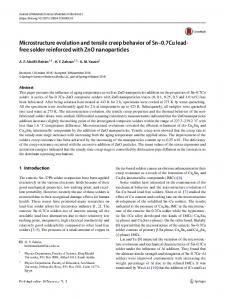
compositions.A Asingle singleBCC BCCstructure structurewas wasalso alsoreported reportedbybyMaiti Maitiand andSteurer Steurer[10], [10],who whostudied studied compositions. ◦ C. Ta Nb Hf Zr Ti that was arc-melted and homogenized for four days at 1600 18.5 25.2 12 was arc-melted and homogenized for four days at 1600 °C. Ta18.5 Nb20.820.8 Hf23.523.5 Zr25.2Ti 12 that Senkov et al. [2] conducted compression tests tests on on Ta Nb20Hf Hf2020Zr Zr2020 roomtemperature temperatureasas Senkov et al. [2] conducted compression Ta20 20Nb20 TiTi 20 20 atatroom ◦ C, 800 ◦ C, 1000 ◦ C and 1200 ◦ C under different strain rates and used Scanning Electron well as at 600 well as at 600 °C, 800 °C, 1000 °C and 1200 °C under different strain rates and used Scanning Electron Microscopy(SEM) (SEM)totoinvestigate investigatethe themicrostructural microstructuralchanges changesduring duringthe thedeformation deformationprocess processand andthe the Microscopy fracturemechanisms. mechanisms.These Theseresearchers researchersclaimed claimedthat thatthe theabove abovetemperature temperaturerange rangecan canbebedivided dividedinto into fracture three regions, each one characterized by different deformation behavior. According to Senkov et al. [2], three regions, each one characterized by different deformation behavior. According to Senkov et al. ◦ ◦ at temperatures up up to 600 C twinning compensates for restricted dislocation mobility. At 800 Grain [2], at temperatures to 600 °C twinning compensates for restricted dislocation mobility. At C 800 °C Boundary Sliding (GBS) is not yet supported by sufficient dislocation mobility and diffusion leads Grain Boundary Sliding (GBS) is not yet supported by sufficient dislocation mobility and diffusionto ◦ cavitation at grain boundaries disappears and cavitation at grain boundaries, while at 1000–1200 leads to cavitation at grain boundaries, while at C 1000–1200 °C cavitation at grain boundaries Dynamic Recrystallization (DRX) occurs. DRX processes are assumed to be responsible for thetorapid disappears and Dynamic Recrystallization (DRX) occurs. DRX processes are assumed be drop in the flow stress after yielding followed by a steady state flow. responsible for the rapid drop in the flow stress after yielding followed by a steady state flow. Thecompression compressiontest testdata data for for Ta Ta20 Nb2020Hf Hf2020 roomtemperature temperatureinclude includecompression compression 20 Ti The 20Nb ZrZr 20Ti 20 20 at atroom yieldstrength strength 929 MPa [9] together fracture than [9]. yield ofof 929 MPa [2] [2] andand 10731073 MPaMPa [9] together with with fracture strainstrain higherhigher than 50% [9].50% High High temperature compression properties seem to be promising as well [2,8]. However, no data temperature compression properties seem to be promising as well [2,8]. However, no data whatsoeverhave havebeen beenpublished publishedininreference referencetototensile tensileproperties propertiesand andcreep creepproperties propertiesofofas-cast as-cast whatsoever Ta Nb Hf Zr Ti under tension. The current paper seeks to fill this gap by focusing on the tensile 20 20 20 20 20 Ta20Nb20Hf20Zr20Ti20 under tension. The current paper seeks to fill this gap by focusing on the tensile and creep properties of the Ta Nb Hf Zr Ti alloy together with its fracture mechanisms. 20 20Ti 2020 alloy 20 and creep properties of the Ta2020 Nb2020 Hf20Zr together with its fracture mechanisms. 2. Results 2. Results Figure 1a depicts a back-scattered SEM image of the gravity-cast material prior to HIP, while Figure 1a depicts a back-scattered SEM image of the gravity-cast material prior to HIP, while Figure 1b shows the suction-assisted casting. Figure 1c,d depict the back-scattered SEM images of Figure 1b shows the suction-assisted casting. Figure 1c,d depict the back-scattered SEM images of these two castings after HIP. Note that both materials were single phased before undergoing HIP, these two castings after HIP. Note that both materials were single phased before undergoing HIP, while a darker phase is discernible inside the bright matrix after HIP. Table 1 provides the respective while a darker phase is discernible inside the bright matrix after HIP. Table 1 provides the respective Energy Dispersive X-ray Spectroscopy (EDS) analyses. It should be noted that the dark phase is evenly Energy Dispersive X-ray Spectroscopy (EDS) analyses. It should be noted that the dark phase is dispersed in the matrix of the gravity-assisted casting, while in the case of the suction-assisted casting evenly dispersed in the matrix of the gravity-assisted casting, while in the case of the suction-assisted it is concentrated mostly at the grain boundaries. casting it is concentrated mostly at the grain boundaries.
(a)
(b) Figure 1. Cont.
Materials 2017, 10, 883
3 of 12
Materials 2017, 10, 883
3 of 11
(d)
(c)
Figure gravity casting suction-assisted Figure1.1.SEM SEMimages imagesofofthe thematerial: material:(a)(a) gravity castingbefore beforeHIP; HIP;(b) (b) suction-assistedcasting castingbefore before HIP; (c) gravity casting after HIP; (d) suction-assisted casting after HIP. HIP; (c) gravity casting after HIP; (d) suction-assisted casting after HIP. Table Table1.1.Energy EnergyDispersive DispersiveX-Ray X-RaySpectroscopy Spectroscopy(EDS) (EDS)results results(at (at%). %).
Sample Phase Sample Phase Gravity casting before HIP overall composition Gravity casting before HIP overall composition Suction-assisted casting before HIP overall composition Suction-assisted casting before HIP overall overallcomposition composition Gravity casting after HIP matrix overall composition Gravity casting after HIP matrixphase darker darker phase overall composition Suction-assisted casting after HIP overall composition matrix Suction-assisted casting after HIP matrix darker phase darker phase
Ti Ti 19.11 19.11 19.13 19.13 19.10 20.30 19.10 20.30 10.88 10.88 20.62 20.62 20.13 20.13 8.52 8.52
Zr Zr 20.66 20.66 21.42 21.42 21.36 21.42 21.36 21.42 48.79 48.79 22.45 22.45 21.58 21.58 57.38 57.38
Nb Nb 21.15 21.15 22.12 22.12 21.53 27.35 21.53 27.35 4.00 4.00 25.73 25.73 27.70 27.70 3.12 3.12
Hf Hf 19.85 19.85 19.46 19.46 18.82 10.78 18.82 10.78 33.26 33.26 13.31 13.31 10.92 10.92 28.51 28.51
Ta Ta 19.24 19.24 17.86 17.86 19.18 20.15 19.18 20.15 3.07 3.07 17.90 17.90 19.67 19.67 2.47 2.47
XRD spectra of both the gravity and the suction-assisted cast samples before HIP (see Figure 2a,b XRD spectra of bothtothe gravity andNbTaTi-based the suction-assisted cast samples HIPcompositions (see Figure 2a,b respectively) correspond single-phase BCC material. The before chemical of respectively) correspond to single-phase NbTaTi-based BCC material. The chemical compositions the considered samples correspond to an overall equi-atomic material composition (see Table 1).of the considered samples correspond an overall material composition (see Table 1).inBased Based on the above described SEM to study, whichequi-atomic indicates the presence of two major phases the on the above described SEM study, which indicates the presence of two major phases in the case of the case of the HfNbTaTiZr alloy that has undergone HIP, each peak was associated with one of these HfNbTaTiZr alloy that has undergone HIP, each peak was associated with one of these two phases: two phases: a roughly equimolar solid solution of ZrHf and a solid solution of NbTaTi, again at a roughly equimolar solid solution of ZrHf and a solid phase solution of NbTaTi, of again atelements roughly equimolar roughly equimolar proportions. As ZrHf solid solution is comprised HCP (at room proportions. As ZrHf solid solution phase is comprised of HCP elements (at room temperature), it has temperature), it has an HCP structure and thus exhibits the characteristic X-ray diffraction pattern of an HCP structure and thus exhibits the characteristic X-ray diffraction pattern of other HCP phases. other HCP phases. Contrary to the ZrHf, the NbTaTi solid solution Contrary toisthe ZrHf, theofNbTaTi solid solution phase is comprised of BCC elements and therefore n phase comprised BCC elements and therefore has a characteristic X-ray diffraction pattern has a characteristic X-ray diffraction pattern of other BCC-structured substances. Figure 2c shows the of other BCC-structured substances. Figure 2c shows the XRD spectra of the gravity-cast HfNbTaTiZr XRD and spectra the gravity-cast HfNbTaTiZr alloy andwhile the HCP/BCC each peak, alloy theofHCP/BCC designation of each peak, Figure 2ddesignation shows theofspectrum ofwhile the Figure 2d shows the spectrum of the suction-assisted cast, both after HIP. suction-assisted cast, both after HIP. Microhardnesstests testsrevealed revealedthe thehardness hardnessofofthe thematerial materialtotobe be323.5 323.5±±6.5 6.5HV HVininthe thecase caseofof Microhardness gravitycasting castingand and330.2 330.2±±9.8 9.8HV HVininthe thecase caseofofsuction-assisted suction-assistedcasting, casting,both bothbefore beforeHIP. HIP.For Forthe the gravity material that underwent HIP, the hardness was found to be 437.2 ± 11.6 HV and 509.1 ± 13.5 HV for material that underwent HIP, the hardness was found to be 437.2 ± 11.6 HV and 509.1 ± 13.5 HV for the gravity and suction-assisted castings respectively. Table 2 summarizes the tension and compression the gravity and suction-assisted castings respectively. Table 2 summarizes the tension and compression testresults resultsatatroom roomtemperature. temperature. test
Materials 2017, 10, 883 Materials 2017, 10, 883
4 of 12 4 of 11
(a)
(b)
(c) Figure 2. Cont.
Materials 2017, 10,10, 883 Materials 2017, 883
5 5ofof1211
(d) Figure2.2.XRD XRDspectra spectraofofHfNbTaTiZr HfNbTaTiZralloy: alloy:(a) (a)gravity gravitycasting castingbefore beforeHIP; HIP;(b) (b)suction-assisted suction-assistedcasting casting Figure before HIP; (c) gravity casting after HIP; (d) suction-assisted casting after HIP. before HIP; (c) gravity casting after HIP; (d) suction-assisted casting after HIP. Table 2. Tension and compression test results. Table 2. Tension and compression test results. Process σy (Mpa) Process σ y (Mpa) Gravity casting Gravity casting Gravity casting Gravity casting casting Tension Suction-assisted Suction-assisted casting Tension Suction-assisted casting Suction-assisted casting Suction-assisted casting Suction-assisted casting Gravity casting 1380 Gravity casting 1380 Gravity casting 1350 Gravity casting 1350 Gravity casting 1749 Compression Gravity casting 1749 Suction-assisted casting 1725 Compression Suction-assisted casting 1725 Suction-assisted casting 1684 Suction-assisted casting 1684 Suction-assisted casting 1888 Suction-assisted casting 1888 Test
Test
σmax (Mpa) σmax (Mpa) 669 749 669 694 749 708 694 678 708 678
The elongation to fracture under tension was below the machine’s detection limit and therefore Thenot elongation to fracture tension the machine’s detection limit and therefore could be measured. The under same was truewas forbelow the differences between the yield stress and the could not be measured. The same was true for the differences between the yield stress and the ultimate ultimate tensile stress. Hence, the maximum stress measured is given in Table 2. Contrary to the tensile stress. thestress maximum measured is given Table 2. Contrary to the tension tension tests,Hence, the yield couldstress be easily detected in the in case of the compression tests. Twotests, creep ◦C the yield stress could be easily detected in the case of the compression tests. Two creep tests at 982 tests at 982 °C were conducted on gravity-cast specimens, the first under a load of 200 MPa and the were conducted on MPa. gravity-cast specimens, the periods first under a load of and 200 MPa andrespectively. the second under second under 120 Both failed after short of time of 15 90 min, 120 MPa. Both failed after short periods of time of 15 and 90 min, respectively. Figure 3a,b provide a general view of the fracture surface of a gravity-cast and a suction-assistedFigure 3a,b provide arespectively. general viewThe of the fracture surface and a suction-assistedcast tension specimen, figures show that of thea gravity-cast fracture is inter-crystalline in both cast tension specimen, respectively. The figures show that the fracture is inter-crystalline in both cases, without any plastic deformation. The fracture of the suction-assisted casting is accompanied cases, without anycracking, plastic deformation. Theintensive fracture at of the the center suction-assisted castingThe is accompanied by intergranular which is most of the specimen. grain size ofby the intergranular cracking, which is most intensive at the center of the specimen. The grain size of the gravity casting varies significantly between the different regions of the fracture surface, while in the gravity varies significantly the different of the fracture surface, while in the case ofcasting the suction-assisted castingbetween the grain size is quiteregions uniform. case ofFigure the suction-assisted grainon size uniform. 4 focuses on casting typical the grains theis quite fracture surface of the above-mentioned tension specimens, showing that no evidence of plastic deformation is discernible in either case. In the case of the gravity cast, the observed grains are characterized by a flake-like surface structure together with some porous regions, while in the case of the suction-assisted cast, brittle fractured grains together with porous regions can be seen.
Materials 2017, 10, 883
6 of 12
Materials 2017, 10, 883
6 of 11
Materials 2017, 10, 883
6 of 11
(a)
(b)
Figure 3. General view of the facture surface of a tension specimen: (a) gravity casting; (b) suctionFigure 3. General view of the facture surface of a tension specimen: (a) gravity casting; assisted casting. (b) suction-assisted casting.
Figure 4 focuses on typical grains on the fracture surface of the above-mentioned tension specimens, showing that no evidence of plastic deformation is discernible in either case. In the (a) observed grains are characterized by a flake-like(b) case of the gravity cast, the surface structure together with Figure some porous regions, while in the case of the suction-assisted cast, brittle fractured grains together 3. General view of the facture surface of a tension specimen: (a) gravity casting; (b) suctionwith assisted porous casting. regions can be seen.
(a)
(b)
Figure 4. Facture surface of: (a) gravity casting; (b) suction-assisted casting.
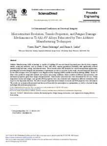
Figure 5 depicts a SEM micrograph showing a general view of the fracture surface of a specimen that crept at 982 °C under 120 MPa. Figure 6 shows a Back Scattered Electron (BSE) image of a selected region of the fracture surface. Figures 5 and 6 show that the fracture is brittle. As revealed by EDS analysis, the surface is (a) (b) contaminated with oxidation products, mainly at the near-surface regions of the sample. Two main Figure 4. surface of: (a) casting; (b) casting. types of broken grains be seen at the surface: brittle cracked grains and porous grains. Figure can 4. Facture Facture surface of:fracture (a) gravity gravity casting; (b) suction-assisted suction-assisted casting. Figure 5 depicts a SEM micrograph showing a general view of the fracture surface of a specimen Figure 5 depicts a SEM micrograph showing a general view of the fracture surface of a specimen that crept at 982 °C under 120 MPa. Figure 6 shows a Back Scattered Electron (BSE) image of a selected that crept at 982 ◦ C under 120 MPa. Figure 6 shows a Back Scattered Electron (BSE) image of a selected region of the fracture surface. region of the fracture surface. Figures 5 and 6 show that the fracture is brittle. As revealed by EDS analysis, the surface is contaminated with oxidation products, mainly at the near-surface regions of the sample. Two main types of broken grains can be seen at the fracture surface: brittle cracked grains and porous grains.
Materials 2017, 10, 883
7 of 12
Materials 2017, 10, 883
7 of 11
Materials 2017, 10, 883
7 of 11
Figure 5. A general view of the fracture surface of a specimen that crept at 982 °C under 120 MPa. Figure 5. A general view of the fracture surface of a specimen that crept at 982 ◦ C under 120 MPa. Figure 5. A general view of the fracture surface of a specimen that crept at 982 °C under 120 MPa.
Figure 6. A BSE images of a selected region of the fracture surface shown in Figure 5. Figure 6. A BSE images of a selected region of the fracture surface shown in Figure 5. Figure 6. A BSE images of a selected region of the fracture surface shown in Figure 5.
3. Discussion 3. Discussion XRD and5 SEM showed that bothisthe gravity-cast specimen and the suction-assisted cast Figures and 6analysis show that the fracture brittle. As revealed by EDS analysis, the surface is XRD and SEM analysis showed that both the gravity-cast specimen and the suction-assisted cast specimen hadwith one oxidation single NbTaTi-based BCC at phase, while bothregions materials were composed of a contaminated products, mainly the near-surface of the sample. Two main specimen had one single NbTaTi-based BCC phase, while both materials were composed of NbTaTi-based BCC phase and a ZrHf HCP phase in their HIP’ed condition. Having analyzed their types of broken grains can be seen at the fracture surface: brittle cracked grains and porous grains. a NbTaTi-based phase a ZrHf HCP in their HIP’ed condition. analyzed XRD spectrum,BCC Senkov at and al. [3] pointed tophase the existence of a BCC phase inHaving both the cast andtheir the XRD spectrum, Senkov at al. [3] pointed to the existence of a BCC phase in both the cast and HIP’ed conditions. Though these researchers reported on a small peak at 2θ = 24.9° indicating the HIP’ed conditions. Though these reported small peak atHCP 2θ =peaks 24.9°detected indicating presence of a hexagonal-like phase,researchers they did not refer to on theasix additional in the presence of a in hexagonal-like they did not to the additional HCP2θ peaks detected in the current study the case of HIPphase, gravity casting: 2θ =refer 31.95°, 2θ =six 34.28°, 2θ = 37.34°, = 47.66°, 2θ = 56.79° current in the HIPrefer gravity casting: 2θ = 31.95°, 2θ =in34.28°, 2θof = 37.34°, 2θ = 47.66°, 2θcasting: = 56.79° and 2θ =study 63.23°. Norcase didof they to the following six peaks the case the suction-assisted and=2θ = 63.23°. Nor 2θ did=they refer the following peaks the case of the suction-assisted casting: 2θ 32°, 2θ = 34.3°, 36.4°, 2θ to = 47.5°, 2θ = 57°six and 2θ =in 62.6°. As stated earlier, identification of 2θ = 32°, 2θ = 34.3°, 2θ = 36.4°, 2θ = 47.5°, 2θ = 57° and 2θ = 62.6°. As stated earlier, identification of
Materials 2017, 10, 883
8 of 12
3. Discussion XRD and SEM analysis showed that both the gravity-cast specimen and the suction-assisted cast specimen had one single NbTaTi-based BCC phase, while both materials were composed of a NbTaTi-based BCC phase and a ZrHf HCP phase in their HIP’ed condition. Having analyzed their XRD spectrum, Senkov at al. [3] pointed to the existence of a BCC phase in both the cast and the HIP’ed conditions. Though these researchers reported on a small peak at 2θ = 24.9◦ indicating the presence of a hexagonal-like phase, they did not refer to the six additional HCP peaks detected in the current study in the case of HIP gravity casting: 2θ = 31.95◦ , 2θ = 34.28◦ , 2θ = 37.34◦ , 2θ = 47.66◦ , 2θ = 56.79◦ and 2θ = 63.23◦ . Nor did they refer to the following six peaks in the case of the suction-assisted casting: 2θ = 32◦ , 2θ = 34.3◦ , 2θ = 36.4◦ , 2θ = 47.5◦ , 2θ = 57◦ and 2θ = 62.6◦ . As stated earlier, identification of the chemical composition of the two phases of the material in its HIP’ed state is based on combining EDS analysis of the two detected phases with the XRD results. Senkov et al. referred to the microstructure of the Ta20 Nb20 Hf20 Zr20 Ti20 after undergoing HIP, claiming that only one BCC solid solution was discernible. However, they emphasized that it was not yet known whether the BCC phase is thermodynamically stable at Room Temperature (RT), or whether it is metastable and thus kinetically restricts formation of the low temperature HCP phase due to slow diffusivity [3]. The current study offers clear evidence of the existence of both a BCC and an HCP phase. It seems that the HIP process is responsible for the appearance of the HCP phase mentioned above. In addition, the hardness values of the gravity-cast material can be regarded as equal to those of the suction-assisted casting if we take into account the overlapping of the standard deviation of the two materials. As for the materials that underwent HIP, it is clear that the HIP process increased the hardness of both castings. Nevertheless, in the case of the materials that underwent HIP, the hardness of the suction-assisted casting was found to be greater than that of the gravity cast. The hardness increase after HIP can be related to the appearance of the secondary HCP phase and its influence on dislocation mobility, similarly to precipitation hardening. The difference between the suction-assisted cast and the gravity cast may be related to the distribution of the ZrHf-rich phase, which is evenly dispersed in the case of the gravity casting while concentrated mainly at the grain boundaries in the case of the suction-assisted casting. An explanation for the HIP process being responsible for the two-phased microstructure can be found when looking at the equilibrium phase diagrams of the elements comprising the alloy. Out of the five constituent elements, Nb and Ta are exclusively BCC elements, while the structure of Ti, Zr and Hf is HCP at low-to-moderate temperatures, undergoing allotropic transformation to BCC at high temperatures. Applying a pseudo-binary simplification and keeping in mind that Ti is the only HCP element, which can be easily stabilized as BCC at room temperature, it is sufficient to look at the elemental pairs Zr-Hf and Nb-Ta, as the HCP and BCC components of such a pseudo-binary system. According to the elemental equilibrium phase diagrams, upon cooling an alloy having a chemical composition close to the equimolar concentration ratio, either the high temperature BCC phase undergoes a eutectoid reaction or precipitation of the HCP component occurs. It is therefore reasonable to derive that when the HIP process of the HfNbTaTiZr alloy ends and the alloy is left to cool at a very slow rate inside the furnace the HCP phase forms out of the original BCC phase, either by a eutectoid reaction or by precipitation. In contrast, an HCP phase is not created in the case of the as-cast alloy due to the rapid cooling, resulting in a supercooled BCC phase. As mentioned earlier, the current study shows that an HCP ZrHf-rich phase appeared after HIP, however, further research is still required in order to confirm the proposed mechanism. As stated earlier, to the best of the authors’ knowledge there are no published data whatsoever regarding tension properties or creep under tension. It should be noted that tensile properties were studied by Senkov et al. [7] but only after being 86.4% cold rolled and 86.4% cold rolled plus annealed at 800 ◦ C and at 1000 ◦ C. The mechanical properties of both castings under compression and under tension are markedly different, as can be seen from Table 2. σy under compression is almost as twice as high as the maximum stress under tension, while in the case of the compression tests conducted on the gravity casting, the results were relatively scattered. This higher degree of scattering may be related
Materials 2017, 10, 883
9 of 12
to the variation in grain size detected in the gravity casting as opposed to the uniform grain size of the suction-assisted casting. The values of σy under compression at room temperature are higher than those reported by Senkov et al.: 929 MPa [2], 1058 MPa [3] and 1073 MPa [9]. The elongation to fracture under tension at room temperature was beneath the machine’s detection limit and therefore could not be measured. Creep tests conducted at 982 ◦ C led to premature failures. For the sake of comparison, according to MAR-M-247 material specifications for the aerospace industry [10,11], the time to rupture of the material should exceed 50 h under 200 MPa at 982 ◦ C. These poor results under tension load lead to the conclusion that the material is extremely brittle and therefore cannot withstand any tension stress applied either at room temperature or at high temperatures. Senkov et al. [7] reported that the 86.4% cold-rolled material showed true tensile strength of 1295 MPa and tensile ductility of 4.7%, however, cold rolling resulted in an extensive grain elongation, formation of deformation bands within the grains, and development of crystallographic textures that depended on the rolling reduction. Annealing lead to recrystallization and to the formation of fine second-phase precipitates which could not be characterized by them [7]. These results, in turn, lead to the conclusion that both the microstructure and the mechanical properties of the HIP’ed material and those of the HIP’ed plus cold rolled material are markedly different. As stated earlier, fractography studies of broken tension test specimens in the case of the gravity casting revealed significant variations in grain size between the different regions of the fracture surface, as opposed to the uniformity of the grain size in the suction-assisted casting. In turn, this may point to casting inhomogeneity in the case of gravity casting, so that suction-assisted casting is preferable. The lack of any evidence of plastic deformation in both gravity and suction-assisted casting is in line with the non-detectable elongations to fracture. The high concentration of oxides beneath the surface detected in the broken creep specimens may be due to preexisting surface cracks through which the oxidation process occurred. Nonetheless, the existence of such open surface cracks, their propagation process and their influence on the poor creep properties of the material under tension should be further investigated. 4. Materials and Methods The Ta-Nb-Hf-Zr-Ti alloy in the form of buttons was prepared by vacuum arc melting of the nominal mixtures of the corresponding elements. The degrees of purity of Ta, Nb, Hf, Zr, and Ti were 99.9%, 99.9%, 99.7%, 99% and 99.7%, respectively. Melting was conducted in a high-purity argon atmosphere. High-purity molten titanium was used as a getter for residual oxygen, nitrogen, and hydrogen. In order to achieve homogeneous distribution of the elements in the alloys, the buttons were turned upside down and re-melted four times. The buttons were approximately 13 mm thick and 35 mm in diameter and had a shiny surface. Following this stage, the alloys were cast into bars of 9 mm in diameter and 85 mm in length. One group of specimens was left to solidify inside the mold after casting. Namely, it underwent a process of gravity casting. The other group was cast by applying suction by means of a vacuum pump. The last stage was Hot Isostatic Pressing (HIP), HIP is a common practice, involving high temperatures and isostatic pressure and it is used for closing internal porosity [12]. HIP was applied in other studies as well as reported [2,3,7,8]. In the current study, the bars underwent HIP at 1230 ◦ C and 152 MPa for 4 h. The bars were then radiographically examined in order to eliminate the existence of porosity and other defects that may lead to premature failure under tension. X-ray Diffraction (XRD) tests were performed using a Stationary Rigaku Smart Lab diffractometer (Tokyo, Japan) equipped with a Cu tube (λKα = 1.5406 Å). An FEI Inspect SEM (Brno, Czech Republic) equipped with an Oxford Energy Dispersive X-ray Spectroscopy (EDS) system was used to analyze the microstructure and the chemical composition of the alloy and its phases as well as the fracture surface. Vickers hardness measurements were conducted using a Seiki Matsuzawa microhardness tester (Tokyo, Japan) under a load of 500 gf. Ten measurements, each lasting 15 s, were taken from the gravity and suction-assisted casts in both states—before and after HIP. Tension, compression and creep specimens were prepared from the HIP’ed bars by machining. Room temperature tension tests and
Materials 2017, 10, 883
10 of 12
creep tests were conducted on similar dog-bone specimens, while compression tests were conducted on cylindrical specimens having a diameter of 8 mm. Both creep and tension specimens were manually polished prior to being tested in order to eliminate machining scratches. Figure 7 shows the cast bar, while Figure 8 depicts a tension/creep specimen. The fracture surfaces of the broken tension and creep specimens were examined by SEM. Materials 2017, 10, 883
10 of 11
Materials 2017, 10, 883
10 of 11
Figure 7. An as-cast bar. Figure 7. An as-cast bar. Figure 7. An as-cast bar.
Figure 8. A tension/creep specimen. Figure 8. A tension/creep specimen. Figure 8. A tension/creep specimen. Table 3. Chemical composition of the as-cast alloy (at %). Table 3. Chemical composition of the as-cast alloy (at %).
Alloy Nb state. Hf Zr Ti Table 3 shows the alloy composition in Ta its as-cast Alloy Ta 20.1 Nb 20.6 Hf 20.7 Zr 18.2 Ti TaNbHfZrTi 20.4 TaNbHfZrTi 20.4 20.1 20.6 20.7 18.2 5. Conclusions 5. Conclusions The microstructure and mechanical properties of gravity-cast and suction-assisted cast Ta20Nb 20Hf20Zr20Ti20 were The microstructure andstudied. mechanical properties of gravity-cast and suction-assisted cast The HIP process, to both castings, was found to be responsible for the appearance of an Ta 20Nb 20Hf 20Zr20Tiapplied 20 were studied. HCPHIP phase in addition to the preexisting BCC The process also increased the hardness The process, applied to both castings, wasstage. found to HIP be responsible for the appearance of an of both castings, and intothe of the suction-assisted led toalso a larger increase. HCP phase in addition thecase preexisting BCC stage. Thecastings HIP process increased the hardness
Materials 2017, 10, 883
11 of 12
Table 3. Chemical composition of the as-cast alloy (at %). Alloy
Ta
Nb
Hf
Zr
Ti
TaNbHfZrTi
20.4
20.1
20.6
20.7
18.2
5. Conclusions
• •
•
• • •
•
The microstructure and mechanical properties of gravity-cast and suction-assisted cast Ta20 Nb20 Hf20 Zr20 Ti20 were studied. The HIP process, applied to both castings, was found to be responsible for the appearance of an HCP phase in addition to the preexisting BCC stage. The HIP process also increased the hardness of both castings, and in the case of the suction-assisted castings led to a larger increase. The HCP phase that appeared after HIP is evenly dispersed in the matrix of the gravity-assisted casting, while it is concentrated mostly at the grain boundaries in the case of the suction-assisted casting. Compression strength values measured for both gravity casting and suction-assisted casting in the current study are higher than those reported in the literature. Creep and tension test results as well as fractography showed that both materials are extremely brittle under tension. A fractography study of the broken tension test specimens revealed significant variations in grain size between the different regions of the fracture surface in the case of the gravity casting, as compared to the uniformity of the grain size in the suction-assisted casting. High concentration of oxides observed beneath the surface of the broken creep specimens may point to preexisting surface cracks through which the oxidation process occurred. Nevertheless, further research is still required in order to understand the failure mechanism.
Acknowledgments: The author wish to thank Dr. Alexander Fleisher, Head of the Foundry Laboratory, Israel Institute of Metals, for his continuous support and Mr. Boris Volfman of Bet Shemesh Engines Ltd. Thanks are also due to Dr. Vladimir Popov and Dr. Aleksey Kovalevsky for their assistance with the casting process. This work is supported by the Israeli Ministry of Economy and Industry (grant number 54663). Author Contributions: Natalya Larianovsky conceived and designed the experiments; Alexander KatzDemyanetz performed the SEM and fractography studies as well as the mechanical properties tests; Eyal Eshed conducted the XRD study, analyzed its results and identified the different phases; Michael Regev analyzed the data and wrote the paper. Conflicts of Interest: The authors declare no conflict of interest.
References 1. 2.
3. 4. 5. 6. 7.
Zhang, Y.; Zuo, T.T.; Tang, Z.; Gao, M.C.; Dahmen, K.A.; Liaw, P.K.; Lu, Z.P. Microstructure and properties of high-entropy alloys. Prog. Mater. Sci. 2014, 61, 1–93. [CrossRef] Senkov, O.N.; Scott, J.M.; Senkova, S.V.; Meisenkothen, F.; Miracle, D.B.; Woodward, C.F. Microstructure and elevated temperature properties of a refractory TaNbHfZrTi alloy. J. Mater. Sci. 2012, 47, 4062–4074. [CrossRef] Senkov, O.N.; Scott, J.M.; Senkova, S.V.; Miracle, D.B.; Woodward, C.F. Microstructure and room temperature properties of a high-entropy TaNbHfZrTi alloy. J. Alloys Compd. 2011, 509, 6043–6048. [CrossRef] Song, H.; Tian, F.; Wang, D. Thermodynamic properties of refractory high entropy alloys. J. Alloys Compd. 2016, 682, 773–777. [CrossRef] Gao, M.K.; Carney, C.S.; Dogan, O.N.; Jablonski, P.D.; Hawk, J.A.; Alman, D.E. Design of refractory high-entropy alloys. JOM 2015, 67, 2653–2669. [CrossRef] Lilensten, L.; Couzinie, J.P.; Perriere, L.; Bourgon, J.; Emery, N.; Guillot, I. New structure in refractory high-entropy alloys. Mater. Lett. 2014, 132, 123–125. [CrossRef] Senkov, O.N.; Semiatin, S.L. Microstructure and properties of a refractory high-entropy alloy after cold working. J. Alloys Compd. 2015, 649, 1110–1123. [CrossRef]
Materials 2017, 10, 883
8. 9. 10. 11. 12.
12 of 12
Senkov, O.N.; Senkova, S.V.; Woodward, C.F. Effect of aluminum on the microstructure and properties of two refractory high-entropy alloys. Acta Mater. 2014, 68, 214–228. [CrossRef] Lin, C.M.; Juan, C.C.; Chang, C.H.; Tsai, C.W.; Yeh, J.W. Effect of Al addition on mechanical properties and microstructure of Alx HfNbTaTiZr alloys. J. Alloys Compd. 2015, 624, 100–107. [CrossRef] Alloy Castings, Investment, Corrosion and Heat Resistant—MAR-M247; Document number ESR 1254; Hamilton Sundstrand: Windsor Locks, CT, USA, 2008. High-Temperature Nickel Casting Alloy (MAR-M247), MTS 1206-1; Issue 2015-11; MTU Aero Engines: Munich, Germany, 2015. Kalpakjian, S.; Schmid, S.R. Manufacturing Engineering and Technology, 5th ed.; Pearson Prentice Hall: Upper Saddle River, NJ, USA, 2006; pp. 494–497. © 2017 by the authors. Licensee MDPI, Basel, Switzerland. This article is an open access article distributed under the terms and conditions of the Creative Commons Attribution (CC BY) license (http://creativecommons.org/licenses/by/4.0/).