materials Article
Effect of Molten Pool Size on Microstructure and Tensile Properties of Wire Arc Additive Manufacturing of Ti-6Al-4V Alloy Qianru Wu, Jiping Lu, Changmeng Liu *, Hongli Fan, Xuezhi Shi, Jie Fu and Shuyuan Ma School of Mechanical Engineering, Beijing Institute of Technology, Beijing 100081, China;
[email protected] (Q.W.);
[email protected] (J.L.);
[email protected] (H.F.);
[email protected] (X.S.);
[email protected] (J.F.);
[email protected] (S.M.) * Correspondence:
[email protected]; Tel.: +86-10-6891-5097 Received: 29 May 2017; Accepted: 29 June 2017; Published: 4 July 2017
Abstract: Wire arc additive manufacturing (WAAM) technique is a cost-competitive and efficient technology to produce large structure components in industry domains. Mechanical properties are mainly dominated by the microstructure of the components, which is deeply affected by the molten pool size. In this work, to investigate the effect of the molten pool size on microstructure and mechanical properties of the components, a series of Ti-6Al-4V alloy blocks with different width of molten pool (WMP) ranging from 7 mm to 22 mm were deposited by adjusting the wire feed speed (WFS) from 100 cm/min to 500 cm/min. It is interesting to find that the macrostructure changes from columnar grains to equiaxial grains, and then returns to large columnar grains with the increase of WMP, which is mainly caused by the different cooling rates and thermal gradients. Nonetheless, the tensile properties of the components have a tendency to decline with the increase of WMP. Keywords: wire arc additive manufacturing; Ti-6AL-4V; molten pool size; microstructure; tensile properties
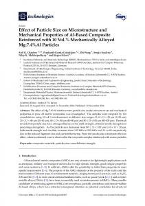
1. Introduction Additive manufacturing (AM) is a relatively novel concept, including laser additive manufacturing (LAM), electron beam additive manufacturing (EBAM) and wire arc additive manufacturing (WAAM). In this way, parts or components are fabricated by adding material in the form of powder or wire in successive layers [1–4]. AM can significantly reduce the time between ideal concept and actual part fabrication and produce components at a very low buy-to-fly ratio, contributing to the great popularity in aerospace, automobile, medical and other domains [5–7]. Mechanical properties, which are dominated by the microstructures of the components, are the most crucial influencing factors in practical application [8,9]. In additive manufacturing process, components are formed by the “micro molten pool” point by point. Consequently, the microstructure of the components is closely related to the solidification of the “micro molten pool”. In particular, the cooling rate and thermal gradient are greatly influenced by the size of the molten pool. For instance, in selective laser melting (SLM) process, as shown in Figure 1a, a small molten pool size about 0.1 mm can be obtained, resulting in a large cooling rate. The microstructures exhibit fine short columnar β grains under such condition [8,10] (Figure 1b), and the tensile properties of components fabricated by SLM are relatively high. On the contrary, in the laser melting deposition (LMD) process in Figure 1c, the molten pool size is much larger, about 3–10 mm. Compared with the components fabricated by SLM, the mechanical properties of the components is relatively poor, with large coarse columnar β grains (2 mm) microstructures, as shown in Figure 1d [11].
Materials 2017, 10, 749; doi:10.3390/ma10070749
www.mdpi.com/journal/materials
Materials 2017, 10, 749 Materials 2017, 10, 749
2 of 11 2 of 11
Figure 1. (a) Schematic of selective laser melting (SLM) process ( represents that the scanning Figure 1. Schematic of selective laser melting (SLM) process (⊗ represents that the scanning direction direction is perpendicular into the plane.); (b) Microstructure of Ti-6Al-4V alloy by SLM [10]; (c) is perpendicular into the plane.); (b) Microstructure of Ti-6Al-4V alloy by SLM [10]; (c) Schematic of Schematic of laser melting deposition (LMD) process and (d) Microstructure of Ti-6Al-4V alloy by laser melting deposition (LMD) process and (d) Microstructure of Ti-6Al-4V alloy by LMD [11]. LMD [11].
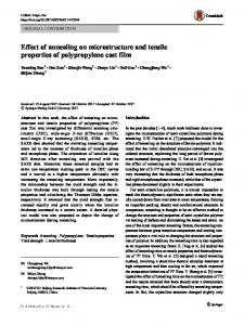
However, the pool size size is usually large in large powder wire feeding additive manufacturing However, themolten molten pool is usually inorpowder or wire feeding additive techniques (i.e., LMD, WAAM and EBAM), which are mainly applied to fabricate large structure manufacturing techniques (i.e., LMD, WAAM and EBAM), which are mainly applied to fabricate components to their high rate. Basically, theBasically, deposition of SLM rate is inof the order large structuredue components duedeposition to their high deposition rate. therate deposition SLM is of the 2–10order g/min, whereas it iswhereas 50–130 g/min for WAAM Nonetheless, under the condition of in of 2–10 g/min, it is 50–130 g/min [6,12]. for WAAM [6,12]. Nonetheless, under the small fluctuation of the molten pool size, the research on the influence of molten pool size on the condition of small fluctuation of the molten pool size, the research on the influence of molten pool macrostructure, microstructure and mechanical of Ti-6Al-4V in WAAM has not size on the macrostructure, microstructure andproperties mechanical propertiessamples of Ti-6Al-4V samples in been reported. WAAM has not been reported. The objective objective of of this molten pool size in in gasgas tungsten arc The this study study is isto toinvestigate investigatethe theinfluence influenceofofthe the molten pool size tungsten welding (GTAW) based WAAM technique. Five different block samples were fabricated under different arc welding (GTAW) based WAAM technique. Five different block samples were fabricated under processing parameters. In addition, finite-element-method simulations of the additive manufacturing different processing parameters. In addition, finite-element-method simulations of the additive process were performed, as well to additionally study the effect of study thermal cycle on of thethermal deposition block manufacturing process were performed, as well to additionally the effect cycle on with different molten pooldifferent sizes. Through with good mechanicalwith properties the deposition block with moltenthis poolstudy, sizes.components Through this study, components good can be obtained with proper pool size, whichmolten is helpful promote optimization in mechanical properties can bemolten obtained with proper pooltosize, whichthe is process helpful to promote the the future. process optimization in the future. ExperimentalProcedures Procedures 2.2.Experimental 2.1. Experimental Setup and Manufacturing Process 2.1. Experimental Setup and Manufacturing Process The experimental setup for WAAM is schematically shown in Figure 2a. The additive The experimental setup for WAAM is schematically shown in Figure 2a. The additive manufacturing process was carried out in the argon shielding atmosphere in an airtight chamber. manufacturing process was carried out in the argon shielding atmosphere in an airtight chamber. The GTAW torch can realize moving upwards and downwards and the workbench can move in the The GTAW torch can realize moving upwards and downwards and the workbench can move in the horizontal plane at a specified speed. The wire was fed into the chamber through an annular feed horizontal plane at a specified speed. The wire was fed into the chamber through an annular feed pipe. A 1.4 mm diameter Ti-6Al-4V wire was used for the deposition process. The substrates used in pipe. A 1.4 mm diameter Ti-6Al-4V wire was used for the deposition process. The substrates used in the experiments were hot rolled Ti-6Al-4V plates with the dimension of 200 mm × 100 mm × 5 mm, the experiments were hot rolled Ti-6Al-4V plates with the dimension of 200 mm × 100 mm × 5 mm, which were treated by mechanical polishing and then fixed on the workbench before being used. which were treated by mechanical polishing and then fixed on the workbench before being used.
Materials 2017, 10, 749
3 of 11
Materials 2017, 10, 749
3 of 11
Figure 2. 2. (a) Schematic of the experimental experimental setup setup developed developed for for wire wire arc arc additive additive manufacturing manufacturing Figure (a) Schematic of the (WAAM) [9]; (b) Sample manufactured by WAAM; (c) Schematic of cross sections of the samples. (WAAM) [9]; (b) Sample manufactured by WAAM; (c) Schematic of cross sections of the samples.
In the current work, the molten pool size was adjusted by changing the wire feed speed (WFS). In the current work, the molten pool size was adjusted by changing the wire feed speed (WFS). The heat input required for per length of the Ti-6Al-4V wire was kept constant (about 21,350 mJ/mm). The heat input required for per length of the Ti-6Al-4V wire was kept constant (about 21,350 mJ/mm). To investigate the influence of the molten pool size on the macrostructure, microstructures and To investigate the influence of the molten pool size on the macrostructure, microstructures and mechanical properties, five wire arc additive manufactured blocks (80 mm long) were fabricated in mechanical properties, five wire arc additive manufactured blocks (80 mm long) were fabricated in this experiment (Figure 2b). All the blocks have three layers, and each layer consists of three beads as this experiment (Figure 2b). All the blocks have three layers, and each layer consists of three beads indicated in Figure 2c. Low frequency pulse current was applied by the power supply in the as indicated in Figure 2c. Low frequency pulse current was applied by the power supply in the experiment. According to careful analysis of previous experiments, optimized deposition parameters experiment. According to careful analysis of previous experiments, optimized deposition parameters were determined (Table 1). There was no preheating during the whole deposition process and the were determined (Table 1). There was no preheating during the whole deposition process and the sample was allowed to cool to the same temperature (70 °C) before each new layer was deposited. sample was allowed to cool to the same temperature (70 ◦ C) before each new layer was deposited. Table 1. Deposition parameters of WAAM. Table 1. Deposition parameters of WAAM. No. No.
1 2 3 4 5
1 2 3 4 5
WFS, cm/min WFS, cm/min
100 100 200 200 300 300 400 400 500 500
Peak Hatch Heat Current, Distance, Input, Peak Hatch Heat Input, Current, A mm mJ/mm Distance, mm mJ/mm A90 4.2 90 4.25.1 140 about 140 5.17.2 170 about 21,350 170 7.2 21,350 210 9.0 210 9.0 270 270 9.89.8
Welding Speed, Welding mm/min
Base-to-Peak
Peak
Time Base-to-Peak Current RatioPeak Time Current Ratio Speed, mm/min Ratio Ratio 100
100
30%
30%
50%
50%
Pulse Frequency, Pulse Frequency, Hz
Length, mm
Hz
1.2
Arc Length, Arc mm
1.2
4
4
2.2. Characterization 2.2. Characterization Two types examination and tensile testing) werewere cut out each Two types of ofsamples samples(for (formicrographic micrographic examination and tensile testing) cut from out from block. Samples for microstructure observation were cut along building direction including the each block. Samples for microstructure observation were cut along building direction including the substrate, and the microstructures were characterized by optical microscopy (Make: Leica, Wetclar, substrate, and the microstructures were characterized by optical microscopy (Make: Leica, Wetclar, Germany; Model: Model: Leica Germany; Leica DM4000M). DM4000M). A A series series of of macro-photographs macro-photographs were were taken taken for for each each block block sample. sample. The resulting image of the entire cross section was used to observe the grain morphology. The macro macro The resulting image of the entire cross section was used to observe the grain morphology. The dimensions and grain dimensions were measured using ImageJ software (https://imagej.net/ImageJ). dimensions and grain dimensions were measured using ImageJ software (https://imagej.net/ImageJ). The samples samples for for micrographic micrographic examination examination were mounted, polished The were mounted, polished with with SiC SiC papers papers (180, (180, 400, 400, 600, 600, 800, 1000, 1500, 2000 grit) ground and then electrolytic polished using a solution consisting of 60 mL mL 800, 1000, 1500, 2000 grit) ground and then electrolytic polished using a solution consisting of 60 perchloric acid acid(60 (60vol vol%), %),390 390 mL methanol ethylene glycol. All the micro-images perchloric mL methanol andand 350350 mL mL ethylene glycol. All of theofmicro-images were were taken from the second layer of deposited blocks, which is also the position of tensile specimens. taken from the second layer of deposited blocks, which is also the position of tensile specimens. Tensile specimens specimens were were extracted extracted parallel parallel to to the the deposition deposition plane plane as as shown shown in in Figure Figure 3a. 3a. The The Tensile tensile specimens specimens had had aa dog-bone dog-bone shape shape with with aa gauge gauge length length of of 10.16 10.16 mm mm and andaa3.18 3.18mm mm×× 0.9 0.9 mm mm tensile cross section [9], as shown in Figure 3b. Over three tensile specimens were taken from each block and cross section [9], as shown in Figure 3b. Over three tensile specimens were taken from each block the parameters of tensile properties are calculated by averaging the measured data. Tensile tests were and the parameters of tensile properties are calculated by averaging the measured data. Tensile tests carried out with an Instron 5966 electronic universal material testing machine at a strain rate of 9.8 × 10⁻⁴ s−1 at room temperature.
Materials 2017, 10, 749
4 of 11
were carried out with an Instron 5966 electronic universal material testing machine at a strain rate of −4 s−1 at room temperature. 9.8 × 102017, Materials 10, 749 4 of 11 Materials 2017, 10, 749
4 of 11
Figure 3. Preparation of tensile samples: (a) Manufacturing procedure of tensile specimens; Figure 3. Preparation of tensile tensile samples: samples: (a) (a) Manufacturing Manufacturing procedure procedure of of tensile tensile specimens; Figure 3. Preparation specimens; (b) Dimensions of tensile of specimens. (b) Dimensions of tensile specimens. (b) Dimensions of tensile specimens.
2.3. Modeling 2.3. Modeling The finite element software package, ABAQUS (Palo Alto, CA, USA) was used for the thermal finite elementEarly software ABAQUS (Palo Alto, CA, forbethe thermal thermal modelThe in this research. studypackage, indicated that the temperature fieldUSA) of thewas arcused would disturbed model in this research. Early study that the field of the arc would be disturbed research. indicated temperature by previous deposition in overlapping deposition process, which leads to the asymmetric distribution bythe previous deposition process, which to the the asymmetric distribution deposition deposition process, which of temperature fieldinofoverlapping the thermaldeposition model (Figure 4a,b) [13]. leads Therefore, whole material was of the temperature fieldreflect of thermal model Therefore, the block wholeinmaterial was temperature of the thethe thermal model (Figure 4a,b) [13]. material modelled to accurately influence of (Figure thermal4a,b) cycle[13]. on the deposition this study. modelled to accurately reflect the influence of thermal cycle on the deposition block in this study. The modelled to accurately reflect the influence of thermal cycle on the deposition block in this study. The height and width of the five deposition block models were measured from the experiments height and Linear width of the of five deposition block models were measured from thethermal experiments separately. The height and width the fivewith deposition block models were from the experiments separately. brick elements 8 nodes (DC3D8) were usedmeasured for the simulation. In Linear brick elements with 8 nodes (DC3D8) were used for the thermal simulation. In order to capture separately. Linear brick elements with 8 nodes (DC3D8) were used for the thermal simulation. In order to capture the high thermal gradients around the heat source during the deposition process, the high thermal gradients around the heat source during the deposition process, dense meshes were order meshes to capture theused highfor thermal gradients thewelding heat source during the deposition process, dense were the bead and thearound area near line. The meshes became coarser in used the bead and areathe near welding line. The meshes coarser in the ±the x direction and dense meshes were used for bead and area near welding line.can The meshes became coarser in the ±xfor direction and −zthe direction away fromthe the welding line, became which largely save calculating − z direction away from the welding line, which can largely save the calculating time of the model the ±x direction and −z direction away from the welding line, which can largely save the calculating time of the model (Figure 4c). (Figure time of 4c). the model (Figure 4c).
Figure 4. Simulated results of arc temperature of (a) single-bead deposition; (b) overlapping Figure 4. 4. Simulated results of of (a)and single-bead deposition; (b) overlapping deposition [13]; (c) Three dimensional thermal model finite element mesh; (b) (d) overlapping Deposition Figure Simulated results of arc arc temperature temperature of (a) single-bead deposition; deposition [13]; (c) Three dimensional thermal model and finite element mesh; (d) Deposition sequence of the block samples; (e) Positions of the two thermocouples on the surface of the substrate. deposition [13]; (c) Three dimensional thermal model and finite element mesh; (d) Deposition sequence sequence of the block samples; (e) Positions of the two thermocouples on the surface of the of the block samples; (e) Positions of the two thermocouples on the surface of the substrate. substrate.
To simulate the material deposition procedure, “element birth technique” was used [14]. All the To simulate the material deposition procedure,at “element birth technique” was used [14]. Allthe the elements of the deposited block were deactivated the initial step of the analysis, and then elementsofofthe thenine deposited block were deactivated at the step of steps the analysis, andthe then the elements tracks are activated in turn (Figure 4d) initial in successive to simulate metal elements of the nine tracks are activated in turn (Figure 4d) in successive steps to simulate the metal deposition. The user subroutine DFLUX (http://ivt-abaqusdoc.ivt.ntnu.no:2080/v6.14/books/sub/ deposition. in The subroutine (http://ivt-abaqusdoc.ivt.ntnu.no:2080/v6.14/books/sub/ default.htm) theuser Fortran code wasDFLUX used to generate the moving heat source for the thermal model. default.htm) in the Fortran code was used to generate the moving heat source for the thermal model.
Materials 2017, 10, 749
5 of 11
To simulate the material deposition procedure, “element birth technique” was used [14]. All the elements of the deposited block were deactivated at the initial step of the analysis, and then the elements of the nine tracks are activated in turn (Figure 4d) in successive steps to simulate the metal deposition. The user subroutine DFLUX (http://ivt-abaqusdoc.ivt.ntnu.no:2080/v6.14/books/sub/default.htm) in the Fortran code was used to generate the moving heat source for the thermal model. In the current work, the Goldak double ellipsoidal heat source [15,16] was used to apply the heat to the additive manufacturing deposition. All the modelling parameters were identical to the experimental conditions, including the dimension of the models, welding speed, the cooling time between subsequent layers, etc. Thermal properties of the material used in the models were from Zhang and Michaleris [17]. The values of convection coefficient and radiation coefficient were determined by running a series of numerical trials based on the experiments. To verify the accuracy of the simulation results, the deposition at WFS of 300 mm/min was selected to compare the numerical thermal histories with the experimental thermal histories. Two thermocouples were attached on the surface of the substrate as marked in red (Figure 4e) to record the temperature during the manufacturing process. The predicted temperatures were extracted from the nodal points in the thermal model where the thermocouples were placed in the experiment. For a given composition, the solidification morphology of the deposited material mainly depends on the velocity of solidification and the thermal gradient [18]. The cooling rate and thermal gradient at the onset of solidification can be extracted from the thermal model results at certain nodal locations. At each nodal location, the solidification cooling rate can be calculated as: TS − TL ∂T = ∂t tS − t L
(1)
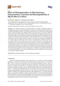
where, TL and TS represent the liquidus and solidus temperatures reached at times tL and tS , respectively. For the material of Ti-6Al-4V used in the current work, the values of TL and TS are 1660 ◦ C and 1604 ◦ C, respectively [17,19]. The thermal gradient G at the time t = tL is obtained from Fourier’s Law: * q * G = ∇ T = (2) k * where q represents the magnitude of the heat flux vector and it can be obtained from the simulation results; k (34 w m−1 ◦ C−1 for Ti-6Al-4V) is the thermal conductivity at the liquidus temperature TL . Then, the solidification velocity R can be calculated by the solidification cooling rate and thermal gradient: 1 ∂T R= (3) G dt Following the calculation of G and R, the expected grain morphology can be predicted as either equiaxed, columnar or mixed by plotting points on the “solidification map” [20]. 3. Results and Discussion 3.1. Macrostructure Figure 5 shows the macroscopic grain morphology of specimens manufactured at different WFS. With the increase of WFS, the width and height of the deposition block increases accordingly. The outline of each deposited bead can be seen clearly, indicating the molten pool size, which has a tendency to increase. The width of molten pool (WMP), total width and total height of the deposition, layer thickness and grain width are measured as shown in Table 2. The WMP (7 mm, 10 mm, 14 mm, 19 mm and 22 mm) can be obtained under each WFS condition.
Materials 2017, 10, 749
6 of 11
Materials 2017,2017, 10, 749 Materials 10, 749
6 of 11 6 of 11
Figure 5. Macroscopic grain morphology of blocks manufactured at the wire feed speed (WFS) of
Figure 5. Macroscopic grain morphology of blocks manufactured at the wire feed speed (WFS) of (a) 100 cm/min; (b) 200 cm/min; (c) 300 cm/min; (d) 400 cm/min and (e) 500 cm/min. Figure 5. Macroscopic morphology of blocks at the wire feed speed (WFS) of (a) 100 cm/min; (b) 200grain cm/min; (c) 300 cm/min; (d)manufactured 400 cm/min and (e) 500 cm/min. (a) 100 cm/min; (b) 200 cm/min; (c) 300 cm/min; (d) 400 cm/min and (e) 500 cm/min. Table 2. Macroscopic parameters at different WFS.
Table 2. Macroscopic parameters at different WFS. Total Width, Total Height, Thickness, Table 2. Macroscopic parametersLayer at different WFS. Average Grain Width,
WFS, WMP, cm/min mm mm mm mm mm Total Total Layer Average Grain 100 cm/min 14.5 5.7 0.72Grain WFS, WMP, 7 WMP, Totalmm Width, Total Height, Layer 1.9 Thickness, Average Width, WFS, Width, mm 8.1 Height, mm 2.7 Thickness, mm Width, mm 200 10 19.0 0.92 cm/min mm mm mm mm mm 23.1 12.3 4.1 0.980.72 7 14.5 14.5 5.7 1.9 0.72 100 300100 7 14 5.7 1.9 400200 19 32.8 13.5 4.5 1.05 0.92 10 19.0 19.0 8.1 2.7 200 10 8.1 2.7 0.92 500300 22 16.5 5.5 1.23 0.98 14 35.2 23.1 12.3 4.1
300 14 23.1 12.3 4.1 0.98 400 19 32.8 13.5 4.5 1.05 400 19 32.8 13.5 4.5 1.05 500 22 10 mm, the 35.2 16.5 1.23 etched mainly5.5 composed of columnar prior 500When WMP 22 is 7 mm or 35.2 16.5cross sections are5.5 1.23
β grains (Figure 5a,b). These grains grow epitaxially and are aligned in the direction of the deposition height across is all7the which indicates steepest gradient direction duringprior When WMP mmthree or 10 10layers, mm, the the etched cross the sections arethermal mainly composed composed of columnar columnar mm or mm, etched cross sections are mainly prior manufacturing process. However, more equiaxial grains appear on the cross section of specimens β grains grains (Figure (Figure 5a,b). 5a,b). These These grains grains grow grow epitaxially epitaxially and and are are aligned aligned in in the the direction direction of the the deposition deposition β manufactured with WMP of 14 mm. Interestingly, when WMP further increases, the equiaxial grains height across all the three layers, which indicates the steepest thermal gradient direction during becomes fewer and the etched cross section exhibits primarily large, columnar grains. The change of manufacturing process. process. However, more more equiaxial equiaxial grains grains appear appear on on the cross section of specimens manufacturing the grain morphologyHowever, with different molten pool sizes is mainly causedthe by the different cooling rate Interestingly, manufactured with WMP of 14 mm. Interestingly, when WMP further increases, equiaxial grains and solidification rate of the molten pool. Meanwhile, with the increase of WMP, thethe grain size keeps becomes fewer and the etched cross section exhibits primarily large, columnar grains. The change becomes fewer because and the of etched cross section exhibits primarily large, columnar The change increasing the reducing cooling rate and the grains become muchgrains. larger and wider of of the grain morphology with different molten sizes is mainly caused by different the different cooling the grain morphology with molten poolpool sizes is mainly caused by the cooling rate (1.23 mm) when WMP is different 22 mm. rate solidification and solidification rate ofmolten the molten pool. Meanwhile, with thehistories increase of WMP, the size grain size Figure 6 shows the between the numerical thermal and the and rate of thecomparison pool. Meanwhile, with the increase of WMP, the experimental grain keeps thermal histories recorded by the thermocouples at the measuring positions, which are indicated in keeps increasing because of the reducing cooling rate and the grains become much larger and wider increasing because of the reducing cooling rate and the grains become much larger and 4e. Based on is the it was found that the thermal models give relatively accurate WMP 22comparison, mm. (1.23Figure mm) when predictions of the temperatures at both the thermocouple positions. Figure 6 shows the comparison between the numerical thermal histories and the experimental
Figure 6 shows the comparison between the numerical thermal histories and the experimental thermal histories recorded by the thermocouples at the measuring positions, which are indicated in Based on on the comparison, comparison, it it was found that the thermal models give relatively accurate Figure 4e. Based predictions of the temperatures at both the thermocouple thermocouple positions. positions.
Figure 6. Temperature verification on the measuring positions of (a) P1 and (b) P2.
Figure 7a shows the temperature field of deposition blocks based on finite-element-method simulations. The grey area represents the molten pool, which corresponds with the bead width well. Figure positions of of (a) (a) P1 P1 and and (b) (b) P2. P2. Figure 6. 6. Temperature Temperature verification verification on on the the measuring measuring positions
Figure 7a shows the temperature field of deposition blocks based on finite-element-method simulations. The grey area represents the molten pool, which corresponds with the bead width well.
Materials 2017, 10, 749
7 of 11
Figure 7a shows the temperature field of deposition blocks based on finite-element-method simulations. The grey area represents the molten pool, which corresponds with the bead width Materials 2017, 10, 749 7 of 11 well. The node near the onset of the solidification is selected to calculate the thermal gradient G node near velocity the onsetRof(Figure the solidification is selected to calculate thermal WFS gradient and in and The solidification 7a), and the relevant values atthe different are Gshown R (Figure 7a), and the relevantofvalues at different WFS are shown in Table 3. In and Tablesolidification 3. In ordervelocity to predict the grain morphology Ti-6Al-4V, the resulting thermal gradient order to predict the grain morphology of the Ti-6Al-4V, the resulting andinsolidification solidification rate values were plotted on solidification mapthermal [18,21],gradient as shown Figure 7b. The rate values were plotted on the solidification map [18,21], as shown in Figure 7b. The finite-elementfinite-element-method simulations predicted that the grain morphology has a tendency to change from method simulations predicted that the grain morphology has a tendency to change from columnar columnar grains to fully equiaxial grains, and then returns to fully columnar grains with the increase grains to fully equiaxial grains, and then returns to fully columnar grains with the increase of WMP, of WMP, which is similar to those observed in the actual cross sections (Figure 5). which is similar to those observed in the actual cross sections (Figure 5).
Figure 7. (a) Temperature field of deposition blocks; (b) Ti-6Al-4V solidification map with simulated
Figure 7. (a) Temperature field of deposition blocks; (b) Ti-6Al-4V solidification map with simulated √ R on the grain morphology of solid solution at a specific C0 for Ti-6Al-4V. data points; (c) Effect of G/ data points; (c) Effect of G/ R on the grain morphology of solid solution at a specific C0 for Ti-6Al-4V. Table 3. Thermal gradient and solidification velocity of the point at the onset of solidification.
Table 3. Thermal gradient and solidification velocity of the point at the onset of solidification. WMP, mm WMP,
Thermal Gradient (G), Thermal k/cm Gradient (G),
Solidification Velocity (R), cm/sVelocity (R), Solidification
mm7
2516 k/cm
10 7 14 1019 1422
1903 2516 1431 1903 1938 1431 2189
0.08868 cm/s 0.07974 0.08868 0.09229 0.07974 0.04866 0.09229 0.04015
G/ R, −1.5√ k cmG/ s−0.5 R, − 1.5 8449 k cm s−0.5 6739 8449 4710 6739 8786 4710 10,925
19 1938 0.04866 8786 22 2189 0.04015 10,925 According to the numerical simulation results and the observed phenomena during the experiments, the possible reasons of the change of grain morphology at different WMP can be summarized as follows. According to the numerical simulation the observed during When WMP is small (7 mm–14 mm), theresults size ofand the feeding wire (1.4phenomena mm in diameter) is the relatively large to the molten pool, as indicated in Figure 8a. The wire can take away part of the heat experiments, the possible reasons of the change of grain morphology at different WMP can be flow. At the WMP of 7 mm and 10 mm, the WFS is relatively slow, namely 100 cm/min and 200 summarized as follows. cm/min, respectively. this mm), condition, the of heat flows(1.4 down through the When WMP is small Under (7 mm–14 the size theprimarily feeding wire mmvertically in diameter) is relatively substrate, and high thermal gradient (G) can be obtained, contributing to the formation of columnar large to the molten pool, as indicated in Figure 8a. The wire can take away part of the heat flow. grains. At the WMP of 14 mm, WFS increases to 300 cm/min accordingly, which means more cool At the WMP of 7 mm and 10 mm, the WFS is relatively slow, namely 100 cm/min and 200 cm/min, wire can be fed into the molten pool. Heat can be largely dissipated by the feeding wire under this respectively. Under this condition, the heat primarily flows down vertically through the substrate, condition. Therefore, the high thermal gradient of the molten pool would be disturbed, and the and high thermal gradient (G) can be obtained, contributing to the formation of columnar grains. epitaxial growth of the columnar grains from the bottom is restricted [22]. Consequently, more At the WMP of 14 mm, WFS increases to 300 cm/min accordingly, which means more cool wire can equiaxed grains can be achieved at the WMP of 14 mm.
be fed into the molten pool. Heat can be largely dissipated by the feeding wire under this condition. Therefore, the high thermal gradient of the molten pool would be disturbed, and the epitaxial growth of the columnar grains from the bottom is restricted [22]. Consequently, more equiaxed grains can be achieved at the WMP of 14 mm.
Materials 2017, 10, 749 Materials 2017, 10, 749 Materials 2017, 10, 749
8 of 11 8 of 11 8 of 11
Figure 8. Schematic of heat dissipation at (a) small width of molten pool (WMP) and (b) large WMP. Figure8.8.Schematic Schematicof ofheat heatdissipation dissipationat at(a) (a)small smallwidth widthof ofmolten moltenpool pool(WMP) (WMP)and and(b) (b)large largeWMP. WMP. Figure
When WMP further increases (19 mm and 22 mm), the size of the feeding wire is very small to When WMP further increases (19 the of the feeding is small Whenpool WMP further increases (19mm mmand and 22 mm), mm), the size sizeof ofthe thesubstrate, feeding wire wire is very very small to to the molten (Figure 8b). Compared with the 22 heat dissipation the heat conducted the molten pool (Figure 8b). Compared with the heat dissipation of the substrate, the heat conducted the molten pool (Figure 8b). Compared with the heat dissipation of the substrate, the heat conducted by the wire can be ignored. Heat mainly flows downward through the substrate. With the increase by by the the wire wire can can be be ignored. ignored. Heat Heat mainly mainly flows flows downward downward through through the the substrate. substrate. With With the the increase increase of thermal gradient G and decrease of solidification velocity R (Figure 7b), the value of G/ √R has of thermal gradient G and decrease of solidification velocity R (Figure 7b), the value of G/ has of thermala gradient G and decrease of solidification velocity R (Figure G/ turn RR has increased lot, thus for a given composition of Ti-6Al-4V (a constant value of C0), the grains to increased aa lot, lot, thus for for aa given given composition composition of of Ti-6Al-4V Ti-6Al-4V (a (a constant constant value value of of C00),), the the grains grains turn turn to to increased coarse columnarthus grains with large WMP (Figure 7c, from point A to B). In this case, coarse columnar coarse columnar columnar grains grains with withlarge large WMP WMP (Figure (Figure 7c, 7c, from from point point A A to to B). B). In In this this case, case, coarse coarse columnar columnar coarse grain growth is promoted. grain growth growth is is promoted. promoted. grain 3.2. Microstructure 3.2. Microstructure Microstructure 3.2. Representative microstructures from the cross sections in the center of the deposition blocks Representative microstructures microstructures from from the the cross cross sections sections in in the the center center of of the deposition deposition blocks blocks (layerRepresentative 2) fabricated with different WMP are shown in Figure 9. The widths of the α-lath were observed (layer 2) fabricated with different WMP are shown in Figure 9. The widths of α-lath were observed (layer 2) fabricated with different WMP are shown in Figure 9. The widths of α-lath by analyzing micrographs and measured using ImageJ software. It can be clearly seenwere that observed with the by analyzing micrographs and measured using ImageJ software. It can be clearly seen that with with the the by analyzing micrographs and measured using ImageJ software. It can be clearly seen that increase of WMP, α structure becomes larger and larger. increase of WMP, α structure becomes larger and larger. increase of WMP, α structure becomes larger and larger.
Figure 9. Microstructure of samples manufactured with WMP of (a) 7 mm; (b) 10 mm; (c) 14 mm; Figure 9. Microstructure samples manufactured with WMP of (a) 7 mm; (b) 10 mm; (c) 14 mm; (d) 19 mm (e) 22 mm. of Figure 9. and Microstructure of samples manufactured with WMP of (a) 7 mm; (b) 10 mm; (c) 14 mm; (d) 19 mm and (e) 22 mm. (d) 19 mm and (e) 22 mm.
Figure 9a,b show the long orthogonally oriented α’-martensitic plates with a needle-like Figure 9a,b show thebeen longreported orthogonally oriented plates withare a needle-like morphology, which have in other studiesα’-martensitic [23]. The α’-lath width similar in Figure 9a,b show thebeen longreported orthogonally oriented α’-martensitic plates withare a needle-like morphology, which have in other studies [23]. The α’-lath width similar in Figure 9a,b. The microstructure difference of Ti-6Al-4V primarily depends on the cooling rate when morphology, which have been reported in other studies [23]. The α’-lath width are similar in Figure 9a,b. Figure 9a,b. The microstructure difference Ti-6Al-4V depends theWMP cooling when the β transforms to α since it cools acrossofthe transus primarily temperature [8]. Atonthe of rate 7 mm or Theβmicrostructure difference ofcools Ti-6Al-4V primarily depends on the cooling ratethe when the β transforms the transforms to α since it across the transus temperature [8]. At WMP of 7 mm or 10 mm, the heat input is relatively low and rapid cooling rate can be achieved due to the small size to mm, α since itheat coolsinput across the transuslow temperature [8]. At the WMP of 7achieved mm or 10 mm, the heat input 10 the is relatively and rapid cooling rate can be due to the small size of the molten pool, thus promoting the formation of needle-like α’ phase. At the WMP of 14 mm, the is the relatively low and rapid coolingthe rate can be achieved due to small of theofmolten of molten thus promoting formation of needle-like α’ the phase. At size the(Figure WMP mm,pool, the basket weave pool, structures can be found, and the α-lath width is slightly larger 9c).14With the thus promoting the formation of needle-like α’ phase. At the WMP of 14 mm, the basket weave basket weave structures can be found, and the α-lath width is slightly larger (Figure 9c). With the increase of WMP, α structures turn to be coarse lath structures in Figure 9d,e. This is mainly because structures can be found, and the α-lath width is lath slightly larger (Figure 9c). With theisincrease of WMP, increase of WMP, α structures turn to be coarse structures in Figure 9d,e. This mainly because heat input increases correspondently at larger WMP, whereas the cooling rate drops rapidly, α structures turn to be correspondently coarse lath structures in Figure 9d,e. This is mainly because heat input increases heat input increases at larger contributing to the increase of α-lath width [24]. WMP, whereas the cooling rate drops rapidly, correspondently at larger WMP, whereas the cooling rate drops rapidly, contributing to the increase of contributing to the increase of α-lath width [24]. α-lath width [24].
Materials 2017, 10, 749
9 of 11
3.3. Tensile Properties Materials 2017, 10, 749
9 of 11
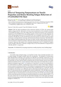
Figure 10 shows the ultimate tensile strength (UTS), yield strength (YS) and the elongation (EL) 3.3. Tensile Properties at failure of tensile specimens derived from the samples fabricated with different WMP. Each group showstests the ultimate tensile yield strength the elongation (EL) increases, includes over Figure three 10 repeat and the last strength results (UTS), are averaged. On(YS) theand whole, with WMP at failure of tensile specimens derived from the samples fabricated with different WMP. Each group both the strength and elongation at failure have a tendency to decline. The ultimate tensile strength includes over three repeat tests and the last results are averaged. On the whole, with WMP increases, of the tensile ranges fromat883 MPa 940 MPa, yield strength ranges 800 MPa to both specimens the strength and elongation failure havetoa tendency to decline. The ultimate tensilefrom strength of theelongation tensile specimens ranges from 883 MPa to 940 yield strength ranges 800 MPaattributed to 826 MPa, and at failure ranges from 7.6% to MPa, 10.5%. These results arefrom primarily to 826 MPa, and macrostructure elongation at failureand ranges from 7.6% to 10.5%. results are primarily attributed the differences in the microstructure (seeThese Figures 5 and 9). to the differences in the macrostructure and microstructure (see Figures 5 and 9).
Figure 10. Tensile properties of samples deposited with WMP ranging from 7 mm to 22 mm.
Figure 10. Tensile properties of samples deposited with WMP ranging from 7 mm to 22 mm. It has been researched that the strengths (i.e., UTS and YS) are related to both the size of α structure and prior β grains [2]. In this study, with the increase of WMP, the size of the β grains It has been researched that the strengths (i.e., UTS and YS) are related to both the size of α structure becomes larger (Figure 5) and the α-lath width keeps increasing (Figure 9), contributing to the and prior β grains [2]. In this study,manufactured with the increase of WMP, the size β grains becomes larger decreasing strength. Samples with small WMP (7 mm andof10the mm), composed of (Figure 5) needle-like and the α-lath width keeps increasing (Figure 9), contributing to the decreasing strength. α’ phase (Figure 9a,b), exhibit higher strength than those manufactured at large WMP, which show much with coarsersmall α-lath (Figure The declining at failure (redof lineneedle-like in Figure 10) α’ phase Samples manufactured WMP9d,e). (7 mm and 10elongation mm), composed is mainly determined by the growing size of the prior β grains [25] (Figure 5). Typically, when WMP (Figure 9a,b), exhibit higher strength than those manufactured at large WMP, which show much reaches 22 mm, the morphology of the cross section has turned into much coarser α-lath within larger coarser α-lath 9d,e).to The declining atperformance. failure (red line in Figure 10) is mainly prior β(Figure grains, leading very poor strengthelongation and elongation determined byHence, the growing size of the prior β grains [25] (Figure 5). Typically, when WMP reaches in the current investigation, the quality of WAAM components manufactured with WMP 7 mm and 10 mm at leastsection the minimum requirements for cast coarser Ti-6Al-4Vα-lath material (elongation 22 mm, theofmorphology offulfill the cross has turned into much within larger prior β at failure of 8% and UTS of 860 MPa, ASTM F1108 [2]). However, only the components manufactured grains, leading to very poor strength and elongation performance. with WMP of 7 mm can meet the requirements for wrought Ti-6Al-4V material (10% and 930 MPa, Hence, in the current ASTM F1472 [2]). investigation, the quality of WAAM components manufactured with WMP
of 7 mm and 10 mm fulfill at least the minimum requirements for cast Ti-6Al-4V material (elongation 4. Conclusions at failure of 8% and UTS of 860 MPa, ASTM F1108 [2]). However, only the components manufactured effect of molten pool requirements size on the microstructure and tensile properties of wire arc additive with WMP of The 7 mm can meet the for wrought Ti-6Al-4V material (10% and 930 MPa, manufactured Ti-6Al-4V has been systematically investigated in this study. Results from physical ASTM F1472 [2]). experiments and numerical simulations can be used to draw the following conclusions.
1 With the increase of WMP, the macrostructure of Ti-6Al-4V changes from columnar grains 4. Conclusions (7 mm and 10 mm) to equiaxial grains (14 mm) firstly and then turns into large epitaxial
The effectcolumnar of molten pool size on22the microstructure properties of wiremap arc additive grains (19 mm and mm). The variation of Gand and Rtensile is plotted on the solidification manufactured Ti-6Al-4V has been systematically investigated in this study. Results from physical experiments and numerical simulations can be used to draw the following conclusions. 1.
With the increase of WMP, the macrostructure of Ti-6Al-4V changes from columnar grains (7 mm and 10 mm) to equiaxial grains (14 mm) firstly and then turns into large epitaxial columnar grains (19 mm and 22 mm). The variation of G and R is plotted on the solidification map of Ti-6Al-4V based on finite-element-method simulations of the additive manufacturing, which
Materials 2017, 10, 749
2.
3.
10 of 11
shows a similar grain morphology to those observed in the actual sections. It seems that equiaxial grains morphology can be obtained by controlling the cooling rate and thermal gradient through adjusting the manufacturing parameters. With WMP of 7 mm and 10 mm, rapid cooling rate can be obtained. The microstructure of the cross sections turns out to be needle-like α’ phase. However, with larger WMP, the microstructure changes into α lath morphology. With the increase of WMP, α-lath width becomes larger and microstructure turns into coarse α plate morphology due to the increasing heat input with larger WMP. Samples manufactured at small WMP (7 mm and 10 mm) exhibit higher strength than those manufactured at larger WMP. The decrease of elongation at failure can be attributed to the growing size of the prior β grains. Typically, when WMP reaches 22 mm, a very poor strength and elongation performance was observed, because of the much coarser α-lath within larger prior β grains at this time.
Acknowledgments: The work was financially supported by the National Natural Science Foundation of China [grant number 51505033] and [grant number 51375052]; Beijing Natural Science Foundation [grant number 3162027]; and Excellent Young Scholars Research Fund of Beijing Institute of Technology [grant number 2015YG0302]. Author Contributions: Qianru Wu performed all experiments and wrote this manuscript. Changmeng Liu designed the research, helped analyze the experimental data and gave some constructive suggestions. Jiping Lu, Hongli Fan, Xuezhi Shi, Jie Fu and Shuyuan Ma participated in the discussion on the results and guided the writing of the article. Conflicts of Interest: The authors declare no conflict of interest.
References 1. 2. 3. 4.
5.
6. 7. 8.
9. 10. 11.
Wang, H.; Jiang, W.; Ouyang, J.; Kovacevic, R. Rapid prototyping of 4043 Al-alloy parts by vp-gtaw. J. Mater. Process. Technol. 2004, 148, 93–102. [CrossRef] Baufeld, B.; Biest, O.V.D.; Gault, R. Additive manufacturing of Ti-6AL-4V components by shaped metal deposition: Microstructure and mechanical properties. Mater. Des. 2010, 31, S106–S111. [CrossRef] Ding, D.; Pan, Z.; Cuiuri, D.; Li, H. A tool-path generation strategy for wire and arc additive manufacturing. Int. J. Adv. Manuf. Technol. 2014, 73, 173–183. [CrossRef] Shi, X.; Ma, S.; Liu, C.; Wu, Q.; Lu, J.; Liu, Y.; Shi, W. Selective laser melting-wire arc additive manufacturing hybrid fabrication of Ti-6AL-4V alloy: Microstructure and mechanical properties. Mater. Sci. Eng. 2017, 684, 196–204. [CrossRef] Acharya, R.; Das, S. Additive manufacturing of in 100 superalloy through scanning laser epitaxy for turbine engine hot-section component repair: Process development, modeling, microstructural characterization, and process control. Metall. Mater. Trans. A 2015, 46, 3864–3875. [CrossRef] Wang, F.; Williams, S.; Colegrove, P.; Antonysamy, A.A. Microstructure and mechanical properties of wire and arc additive manufactured Ti-6Al-4V. Metall. Mater. Trans. A 2013, 44, 968–977. [CrossRef] Wu, Q.; Ma, Z.; Chen, G.; Liu, C.; Ma, D.; Ma, S. Obtaining fine microstructure and unsupported overhangs by low heat input pulse arc additive manufacturing. J. Manuf. Process. 2017, 27, 198–206. [CrossRef] Rafi, H.K.; Karthik, N.V.; Gong, H.; Starr, T.L.; Stucker, B.E. Microstructures and mechanical properties of Ti-6AL-4V parts fabricated by selective laser melting and electron beam melting. J. Mater. Eng. Perform. 2013, 22, 3872–3883. [CrossRef] Guo, J.; Zhou, Y.; Liu, C.; Wu, Q.; Chen, X.; Lu, J. Wire arc additive manufacturing of AZ31 magnesium alloy: Grain refinement by adjusting pulse frequency. Materials 2016, 9, 823. [CrossRef] Simonelli, M. Microstructure Evolution and Mechanical Properties of Selective Laser Melted Ti-6AL-4V. Doctoral Thesis, Loughborough University, Loughborough, UK, 2014. Lu, Y.; Tang, H.; Fang, Y.; Liu, D.; Wang, H. Microstructure evolution of sub-critical annealed laser deposited Ti-6AL-4V alloy. Mater. Des. 2012, 37, 56–63. [CrossRef]
Materials 2017, 10, 749
12.
13. 14. 15. 16.
17. 18.
19. 20. 21. 22.
23. 24. 25.
11 of 11
Suryakumar, S.; Karunakaran, K.P.; Bernard, A.; Chandrasekhar, U.; Raghavender, N.; Sharma, D. Weld bead modeling and process optimization in hybrid layered manufacturing. Comput.-Aided Des. 2011, 43, 331–344. [CrossRef] Zhou, X.; Zhang, H.; Wang, G.; Bai, X. Three-dimensional numerical simulation of arc and metal transport in arc welding based additive manufacturing. Int. J. Heat Mass Transf. 2016, 103, 521–537. [CrossRef] Shan, X.Y.; Tan, M.J.; O’Dowd, N.P. Developing a realistic FE analysis method for the welding of a net single-bead-on-plate test specimen. J. Mater. Process. Technol. 2007, 192–193, 497–503. [CrossRef] Goldak, J.; Chakravarti, A.; Bibby, M. A new finite element model for welding heat sources. Metall. Tran. B 1984, 15, 299–305. [CrossRef] Ding, J.; Colegrove, P.; Mehnen, J.; Ganguly, S.; Almeida, P.M.S.; Wang, F.; Williams, S. Thermo-mechanical analysis of wire and arc additive layer manufacturing process on large multi-layer parts. Comput. Mater. Sci. 2011, 50, 3315–3322. [CrossRef] Zhang, L.; Michaleris, P. Investigation of lagrangian and eulerian finite element methods for modeling the laser forming process. Finite Elements Anal. Des. 2004, 40, 383–405. [CrossRef] Klingbeil, N.; Brown, C.; Bontha, S.; Kobryn, P.; Fraser, H. Prediction microstructure in laser deposition titanium alloys. In Proceedings of the Solid Freeform Fabrication Proceedings, Austin, TX, USA, August 2002; pp. 142–149. Ding, J. Thermo-Mechanical Analysis of Wire and Arc Additive Manufacturing Process. Ph.D. Thesis, Cranfield University, Cranfield, Bedfordshire, UK, 2012. Kobryn, P.A.; Semiatin, S.L. The laser additive manufacture of Ti-6AL-4V. J. Miner. Met. Mater. Soc. 2001, 53, 40–42. [CrossRef] Kobryn, P.A.; Semiatin, S.L. Microstructure and texture evolution during solidification processing of Ti-6Al-4V. J. Mater. Process. Technol. 2003, 135, 330–339. [CrossRef] Fu, J.; Gong, L.; Zhang, Y.; Wu, Q.; Shi, X.; Chang, J.; Lu, J. Microstructure and mechanical properties of Ti-6Al-4V fabricated by vertical wire feeding with axisymmetric multi-laser source. Appl. Sci. 2017, 7, 227. [CrossRef] Baufeld, B.; Biest, O.V.D.; Dillien, S. Texture and crystal orientation in Ti-6Al-4V builds fabricated by shaped metal deposition. Metall. Mater. Trans. A 2010, 41, 1917–1927. [CrossRef] Lütjering, G. Influence of processing on microstructure and mechanical properties of (α + β) titanium alloys. Mater. Sci. Eng. A 1998, 243, 32–45. [CrossRef] Leyens, C.; Peters, M. Titanium and Titanium Alloys; Wiley-VCH: Weinheim, Germany, 2003. [CrossRef] © 2017 by the authors. Licensee MDPI, Basel, Switzerland. This article is an open access article distributed under the terms and conditions of the Creative Commons Attribution (CC BY) license (http://creativecommons.org/licenses/by/4.0/).