MIMO – A SOLUTION FOR ADVANCED WIRELESS ACCESS?
M.A. Beach, D.P. McNamara, P.N. Fletcher & P. Karlsson University of Bristol, Bristol. BS8 1TR E-Mail:
[email protected]
Abstract The application of Smart Antenna technology to wireless communication systems has attracted considerable attention over the last decade or so, as a means of capacity enhancement. Here, the application of space-time processing using a single antenna array at the base-station has been considered in order to obtain interference reduction (both co-channel and multi-path) as well as range extension. More recently, the application of dual antenna array architectures to create multiple-input multiple-output (MIMO) configurations, has attracted considerable interest both within academia and industry as a means of providing significant capacity gains over conventional array based enhancement methods. This paper provides an introduction to these MIMO communication systems and explains how such capacity gains can be achieved using this technology.
1.
INTRODUCTION
In order to realise the full potential of, ‘Any Where, Any Time Personal Communications’, which includes high bit-rate real-time multimedia applications, space-time adaptive signal processing is now regarded as a core element of future system deployments [1]. Until recently, it was envisaged by those engaged in wireless system design that spacetime processing in the form of adaptive or smart antennas employing a single antenna array [2][3], would provide the long-term means to offer sufficient user capacity within the confines of the limited radio spectrum allocated to these systems. Conventional ‘smart’ antenna systems yield a capacity enhancement or range extension over conventional fixed beam antenna installations by focussing their beam patterns towards an addressed volume associated with the signalling space of the desired traffic channel. This both reduces the interference [4] caused by, and also seen by, this channel, hence providing a capacity enhancement through Spatial Filtering Interference Reduction (SFIR), or Space Division Multiple Access (SDMA). Numerous test-beds or validators have been constructed in order to provide further ‘proofs-ofconcept’ as well as to inform the industry and network operators about this potential of this technology. This has been conducted both privately
within numerous organisations [5][6], as well as publicly under initiatives such as the European RACE1 and ACTS2 programmes [7][8][9]. Despite these benefits offered by single array based solutions, 3rd Generation Wireless networks (e.g. UMTS and beyond) could still fall short of market expectations in terms of available capacity for ‘e-commerce’ and ‘multi-media’ based services. As recently reported in the literature [10], the smart antenna concept can be extended by employing multielement arrays at both ends of the communications link. This MIMO architecture has the ability to exploit the multipath scattering present in the environment in order to realise substantial gains in both link and network capacities. If practically viable, this novel approach could offer a unique solution for supporting bandwidth hungry wireless applications in future generation networks. 2.
FUNDAMENTALS OF MIMO SYSTEMS
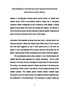
It is well understood that a multi-element antenna array can be employed to obtain independent fading signals from a multipath rich environment and a processing gain realised through the application of optimum combining [11]. This concept can be extended by employing multi-element arrays at both ends of the communications link [10], thereby exciting independent paths between each of the transmit and receive elements Figure 1. RX
TX
Figure 1:
Creation of a MIMO channel
1
“Research into Advanced Communications for Europe”
2
“Advanced Communications Technologies Societies”
ρ C = log 2 det I nR + HH * bits/s/Hz (1) nT The normalised channel matrix, H, is obtained from the absolute (measured) channel response, G, by removing the average path loss component [12], as follows
( )
1/ 2 H = Pˆ P ⋅ G
(2)
where Pˆ is the total transmitted power and P is the average power over all receive elements. As mentioned above, this matrix channel corresponds to the creation of multiple paths between the transmit and receive arrays. The relative (power) gains of each of these parallel channels are given by the eigenvalues, λi, of the channel covariance matrix, HH* (with the absolute channel gains being given by the eigenvalues of GG*). It can therefore be seen that in order to create n parallel channels, the channel matrix G must be of at least rank n. In reality, this desire for the channel matrix to have high rank translates to the requirement for each receive antenna element to experience independent fading. Although an environment may exhibit sufficient multipath scattering to induce independent
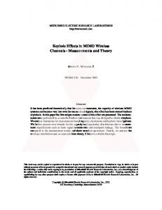
fading across the arrays, this independence still does not guarantee decorrelation of the channel matrix. There is therefore a finite probability that even in a highly scattering environment a MIMO channel matrix can become ill-conditioned. This therefore causes the lowest of the gains of the spatial channels to significantly drop, as shown by the absolute channel gains in Figure 2 at about 2.4 seconds (if the correlation between elements was worse then more of the gains would also be seen to drop). -30
-40
Path Gain, dB
It has been shown [12] that when these dual arrays are deployed in a suitably rich scattering environment there is considerable potential for obtaining extremely high spectral efficiencies. Assuming a minimum of n antenna elements at each of the transmitter and receiver, then n parallel channels will effectively be created between the transmitter and receiver, thus increasing the spectral efficiency n times. (The number and quality of these parallel channels is dependent on the instantaneous propagation conditions). This implies a linear increase in the channel capacity with increasing numbers of antenna elements, as opposed to the logarithmic increase normally associated with multi-antenna diversity techniques. For a narrowband system, the complex channel response between a single element at the transmitter and receiver can be represented as a single complex number. The full channel response of a system comprising of nT transmit elements and nR receive elements, can therefore be described by an nR-by-nT matrix, G, (where element Gij is the response between receive element i and transmit element j). The information theoretic capacity of this channel, for fixed numbers of antenna elements, is a function of both the average received signal to noise ratio at each receive element, ρ, and the normalised channel response matrix, H, as shown in (1) [12]. (This assumes that the transmitter does not have knowledge of the channel response, and hence distributes its power equally amongst the nT elements).
-50
-60
-70
-80 0
Figure 2:
1
2 3 Time, seconds
4
5
Measured gains of all ‘spatial channels’ created by an 8x8 MIMO system in an indoor environment [13].
It is the creation of these parallel channels that gives rise to the high capacities of MIMO systems. Since each of these ‘spatial channels’ is orthogonal to each of the others, they are all capable of supporting independent data streams. The capacity of the overall MIMO channel can therefore also be calculated as the sum of the classical Shannon capacities (log2(1+SNR)) of each of these spatial channels (modified by their individual channel gains), as in (3), which can be shown to be equal to (1).
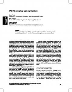
λi (3) T i In order to quantify some of these claims of huge capacities, Figure 3 shows an example of the complementary cumulative distribution functions (CCDFs) of MIMO channel capacity for both measured and statistically generated channels. The statistically generated channels represent an ideal Rayleigh fading environment and hence the best possible conditions for generating high MIMO capacities. All elements of these statistically generated channel matrices are therefore modelled as independent identically distributed (i.i.d.), complex, zero mean, unit variance random variables [12], such that: C=
ρ
∑ log 1 + n 2
Hij = Normal(0,1/ 2 ) +
− 1 Normal(0,1/ 2 ) (4)
In comparison, it can be seen that although the capacities of the measured channels (from an indoor environment [14]) are indeed lower than those of an
ideal Rayleigh environment, significant spectral efficiencies are still achieved with high probability. 1 Measured Probability (Capacity > Abscissa)
Statistical 0.8
0.6 Increasing ρ 0.4
0.2
0 0
5
Figure 3:
10
15 20 Capacity, bits/s/Hz
25
30
Capacity CCDFs of measured and statistically generated channels for ρ increasing in 3dB steps between 0 and 21dB. (4-element 0.5λ-spaced arrays).
Figure 3 also illustrates how, even for relatively low numbers of transmit and receive elements, very large spectral efficiencies can be obtained. For example, with a signal to noise ratio of 21dB and an outage probability of 10%, the measured channels achieved a capacity of just over 15bits/s/Hz. To achieve the same capacity using a single transmitter would require a modulation scheme with 215 = 32,768 constellation points!
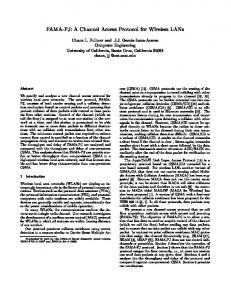
For both schemes, the demultiplexer divides the incoming data into nT individual bit streams (labelled a to d for the 4 tx-element example in Figure 5). For V-BLAST, each demultiplexed data stream is always assigned (uncoded) to the same transmit antenna element as in Figure 5a. (Although the original VBLAST scheme itself does not incorporate any coding, it can be concatenated with an outer code for improved performance [17]). However, in D-BLAST each data stream is encoded individually and then cyclically assigned to a different antenna in each symbol period (Figure 5b). The transmission of each coded stream is therefore distributed in both space and time. Antenna 1 2 3 4
a b c d
a b c d
a b c d
a b c d
a b c d
a b c d
a b c d
t
t+1
t+2
t+3
t+4
t+5
t+6
Time
(a) V-BLAST Antenna 1 2 3 4
a b c d
d a b c
c d a b
b c d a
a b c d
d a b c
c d a b
t
t+1
t+2
t+3
t+4
t+5
t+6
Time
(b) D-BLAST 3.
MIMO ARCHITECTURES
Figure 5:
Demux
TX Data
Signal separation
a) Bell Labs Layered Space-Time (BLAST) [15] Bell Labs were the first to propose an architecture and present a reconstruction algorithm to exploit MIMO channels. This was given the acronym BLAST (Bell Labs Layered Space Time). Two variations of BLAST exist; Diagonal (D-BLAST) [10] and Vertical (V-BLAST) [16] (the prefix denoting the direction in which the received signals are processed in space and time).
Modulation & Upconversion
Figure 4:
RX Data
Downconversion
BLAST system architecture
The same general system architecture is common to both BLAST schemes (Figure 4), although the demultiplexing and signal separation operations are different.
Assignment of data streams to transmit antenna elements
The signal separation and detection of the VBLAST algorithm works on a symbol by symbol basis, using a combination of nulling and symbol cancellation [16][18]. Conversely, D-BLAST processes the received signals corresponding to each coded stream individually [10] (the diagonal layers in space-time). For example, having detected one diagonal containing stream a in Figure 5b this would be cancelled out and processing would continue on diagonals containing streams d, c, b and a again, etc. For both these schemes to function there must be at least as many receive antenna elements as there are transmit elements, although any further increase in the number of receive elements above this can be used to help improve detection performance [10]. Secondly, both detection processes also require accurate knowledge of the MIMO channel response matrix and hence any implementation must also include channel estimation [19][20]. As an example of the performance achievable by these architectures, a demonstrator implementing the V-BLAST scheme has been reported [16] by Bell Labs to achieve spectral efficiencies of between 20 and 40bps/Hz in an indoor environment.
b) Space-Time Coding In many environments it may not be practical to exploit the very high spectral efficiency properties of the MIMO channel. This could be true in situations where the high variability of the channel characteristics gives rise to a significant variation in the number of parallel spatial paths capable of carrying data. In such a case, architectures trying to extract maximum spectral efficiency from the channel, as described previously, could suffer from catastrophic bit error failure. Space-time coding techniques provide an alternative method for extracting an advantage from MIMO channels [21]. Rather than using the parallel channels for increased spectral efficiency, they are employed so as to give a greatly increased diversity order and, in some cases, coding gain. In this way, a reduction in the number of parallel channels will only result in decreased diversity and not necessarily in system failure. These techniques were initially derived from investigations into transmit diversity [22]. This can be seen from inspection of the delay diversity scheme in Figure 6, where the channel encoder is a rate ½ repetition code. Although this gives a diversity advantage without bandwidth expansion (since two symbols are transmitted simultaneously), it was questioned whether a more efficient channel encoder could be found [23] that would also realise some coding gain. Modulation & Upconversion TX Data
Channel Encoder
Serial to Parallel
Delay
Figure 6:
employed at the receiver transmitted data stream. Constellation
2
the
1
00
01
02
03
2
10
11
12
13
3
20
21
22
23
4
30
31
32
33
0
3
Figure 7:
Example of a 4-PSK 4-state space-time trellis code for 2 Transmit Antennas [23]
These space-time trellis codes are able to offer significant coding gains, although this is at the expense of larger numbers of states and hence higher complexity which also increases exponentially with the number of antenna elements. Space-time block codes are therefore attractive since schemes have been found [24][25] which allow the use of only linear processing at the receiver. These codes are able to achieve the full diversity order possible for a given number of antennas and without bandwidth expansion, although they do not offer the coding gains possible with space-time trellis codes. It is this provision of transmit diversity whilst maintaining relatively simple processing that has made the scheme in [24] the first space-time code to be included in a standard for future systems (3GPP proposal for UMTS [26]). This scheme uses a simple block coding algorithm to encode pairs of symbols for transmission by two antennas. Blocks of two consecutive symbols, s0 and s1, are taken from the input data stream and used to generate the transmission sequence for each antenna as described in Table 1 (where T is the symbol period and * is complex conjugate).
Modulation & Upconversion
Delay diversity transmission scheme
The removal of the delay block shown in Figure 6, and an extension to allow any number of outputs from the serial to parallel converter gives a generalised architecture. This has led to the development of space-time channel encoders of which, as in conventional coding theory, both block and trellis forms exist. Space-time trellis coding is a combination of coding and modulation for multiple transmit antennas that achieves both a diversity and coding gain. These codes can be designed according to criteria derived in [23] in order to trade off the diversity and coding gains against each other. The encoder is based on a finite state-machine with the state transitions being determined by the input data bits. Each of these state transitions identifies the symbols that are transmitted from each of the antennas as shown in Figure 7. Maximum likelihood sequence estimation is then
reconstruct
Outputs for each transition
State
1
to
Table 1:
Time
Antenna 0
Antenna 1
t t+T
s0 -s1*
s1 s0*
Space-time block encoder for 2 transmit antenna elements [24]
Although this is only specified for two transmit and one receive element, the scheme can also accommodate additional antennas at the receiver, increasing the overall diversity order to 2nR, where nR is the number of antenna elements at the receiver. 4.
APPLICATION OF MIMO TECHNIQUES
Even given the current extent of research into MIMO and space-time techniques, there is still much work to be undertaken before a complete understanding of all aspects of this these systems is approached. Due to the obvious commercial value of this technology in the light of the cost and scarcity of
radio spectrum, this research is progressing rapidly, with some products and standards already being proposed (e.g. [27][28] amongst others). The majority of these are currently being developed for the broadband fixed wireless access (FWA) market, for two main reasons. Firstly, there is an undoubted demand for this service [29] as the requirement for delivery of high bandwidth services direct to homes and offices grows. Secondly though, from a technical perspective, the fixed nature of such a system provides a more forgiving propagation environment than high mobility cellular systems. This allows some of the constraints on aspects such as channel estimation and/or equalisation to be relaxed, therefore easing initial practical implementation. Future wireless LANs are also receiving attention as systems that could benefit from the high data rates MIMO architectures could support [30], especially since indoor environments inherently provide high levels of multipath scattering [14]. Finally though, with further development of MIMO technology and increasing integration, there will be a point at which even cellular networks will be able to implement these techniques [31]. 5.
CONCLUSION Given the predicted capacity gains of MIMO techniques and the current volume research and development activities within both industry and academia, considerable technological advances within this field are now likely. ACKNOWLEDGEMENTS The authors gratefully acknowledge the financial support from the UK EPSRC, DERA and the CEC IST SATURN project in conjunction with the preparation of this paper.
[8]
[9]
[10]
[11] [12]
[13]
[14]
[15] [16]
[17]
[18]
[19]
[20]
[21]
[22]
REFERENCES [1]
[2]
[3]
[4] [5]
[6]
[7]
Y.J. Guo, S.Vadgama & Y. Tanaka, “Advanced Base Station Technologies for UTRAN”, IEE E.C.E.J., Vol.12, No.3, June 2000, p123-132. S.C. Swales, M.A. Beach, D. Edwards & J.P. McGeehan, “The performance enhancement of multi-beam adaptive base station antennas for cellular land mobile radio systems”, IEEE Trans. Vehicular Tech., Vol. 39, 1990, pp.56-67. A.F. Naguib, A Paulraj & T. Kailath, “Capacity improvement with base-station antenna arrays in cellular CDMA”, IEEE Trans. Vehicular. Tech., Vol. 43, pp691-698. J Litva & T Lo, Digital Beamforming in Wireless Communications, Artech House, 1996. C Ward, D Adams, F Wilson, A Bush, “The Live-Air Trials of a Multibeam Cellular Base Station Antenna System”, Proc. IEE ICAP’99, University of York, 1999, pp169-172. S Anderson, B Hagerman, D Henrik, U Forssin, J Karlsson, F Kronestedt, S Mazur, “Adaptive Antennas for GSM and TDMA systems”, IEEE Personal Comm. Magazine, June 1999, pp74-86. G Tsoulos, J McGeehan & M.A. Beach, “Space Division Multiple Access (SDMA) Field Trials. Part 1: Tracking and
[23]
[24]
[25]
[26] [27] [28] [29] [30] [31]
BER Performance”, IEE Proc. Radar, Sonar Navig., Vol.145, No. 1, Feb 1998, p73-78. C. Evci. et al, “AWACS: ATM Wireless Access System – potential candidate for European HIPERLINK standard”, Int. J. of Comp. & Telecom. Net., Elsevier, Vo1 31, 1999. C.M. Simmonds, P.B. Darwood, M.A. Beach & P.Howard, “TSUNAMI (II) Macrocellular Field Trial System Performance in the Presence of Deliberate Interference”, IEE ICAP 1999, p73-76. G.J. Foschini, “Layered Space-Time Architecture for Wireless Communication in a Fading Environment When Using Multiple Antennas”, Bell Labs. Tech. Journal, Vol 1, No 2, Autumn 1996, pp. 41-59. J.D. Parsons, Mobile Radio Propagation Channel, 2nd Edition, Wiley, 2000. G.J. Foschini and M. J. Gans, “On Limits of Wireless Communications in a Fading Environment When Using Multiple Antennas”, Wireless Personal Communications, Vol. 6, No. 3, March 1998, p. 311. D.P. McNamara, M.A. Beach, & P.N. Fletcher, “Temporal Variation of Multiple-Input Multiple-Output (MIMO) Channels in Indoor Environments”, IEE Int. Conf. On Antennas & Propagation (ICAP’01), April 2001. D.P. McNamara, M.A. Beach, P.N. Fletcher & P. Karlsson, “Initial Investigation of Multiple-Input Multiple-Output (MIMO) Channels in Indoor Environments”, IEEE Benelux Chapter Syp. On Veh. Tech. & Comms, Leuven, Oct. 2000. http://www.bell-labs.com/project/blast/ P.W. Wolniansky, G.J. Foschini, G.D. Golden, R.A. Valenzuela, “V-BLAST: An Architecture for Realizing Very High Data Rates Over the Rich-Scattering Wireless Channel”, Proc. ISSSE’98, Pisa, Italy, Sept. 29, 1998. X. Li, H. Huang, G.J. Foschini & R.A. Valenzuela, “Effects of Iterative Detection and Decoding on the Performance of BLAST”, Proc. IEEE Globecom, San Francisco, Nov. 2000. G.J. Foschini, G.D. Golden, R.A. Valenzuela & P.W. Wolniansky, “Simplified Processing for High Spectral Efficiency Wireless Communication Employing MultiElement Arrays”, IEEE J.S.A.C., Vol. 17, No. 11, Nov. 1999. T.L. Marzetta, “Blast Training: Estimating Channel Characteristics for High Capacity Space-Time Wireless”, Proc. 37th Allerton Conf., Monticello, Sept. 22-24th, 1999. B. Hassibi & B.M. Hochwald, “How Much Training is Needed in Multiple-Antenna Wireless Links?”, Submitted to IEEE Trans. Info. Theory. A.F. Naguib, N. Seshadri & A.R. Calderbank, “Increasing Data Rate Over Wireless Channels”, IEEE Signal Processing Magazine, May 2000. A. Wittneben, “A New Bandwidth Efficient Transmit Antenna Modulation Diversity Scheme for Linear Digital Modulation”, Proc. IEEE ICC’93, Geneva, 1993. V. Tarokh, N. Seshadri, A.R. Calderbank, “Space-Time Codes for High Data Rate Wireless Communication: Performance Criterion and Code Construction”, IEEE Trans. on Info. Theory, Vol 44, No 2, March 1998, pp. 744-765. S.M. Alamouti, “A Simple Transmit Diversity Technique for Wireless Communications”, IEEE J.S.A.C., Vol 16, No 8, October 1998, pp. 1451-1458. V. Tarokh, H. Jafarkhani, A.R. Calderbank, “Space-Time Block Codes from Orthogonal Designs”, IEEE Trans. on Info. Theory, Vol 45, No 5, July 1999, pp. 1456-1467. 3GPP Technical Specification, TS 25.211, V3.1.1, Dec. 1999. http://www.iospanwireless.com http://www.bwif.com R. Dettmer, “
[email protected]”, IEE Review Magazine, Vol 46, No 1, January 2000, pp. 13-18. http://www.ist-saturn.org http://www.ist-metra.org
British Crown Copyright, 2000/DERA Published with the permission of the controller of Her Britannic Majesty’s Stationery Office