Minimizing Network Complexity through Integrated Top-Down Design Xin Sun
Geoffrey G. Xie
School of Computing and Information Sciences Florida International University
Department of Computer Science Naval Postgraduate School
[email protected]
[email protected]
ABSTRACT
of enterprise network operational requirements (e.g., security policy represented by a reachability matrix [35]). Moreover, the configuration complexity of these designs can vary greatly. In other words, some designs may incur much higher configuration complexity than others while accomplishing the same objectives. The unnecessarily high configuration complexity is highly undesirable as it can lead to a huge increase in both the amount of manual intervention required for managing the network and the likelihood of configuration errors. For example, a research report [20] discloses that 80% of enterprise IT budget is devoted to maintaining the status quo. Despite this investment, configuration errors account for 50-80% of network outages [18, 20] and enable 65% of all successful cyber-attacks [28]. There is a general perception that complexity is the primary cause of high human costs, and interviews and anecdotal evidence suggest that an operator’s ability to run a network decreases as the network becomes more complex [7].
The network design process today remains ad-hoc and largely complexity agnostic, often resulting in suboptimal networks characterized by excessive amounts of dependencies and commands in device configurations. The unnecessarily high configuration complexity can lead to a huge increase in both the amount of manual intervention required for managing the network and the likelihood of configuration errors, and thus must be avoided. In this paper we present an integrated top-down design approach and show how it can minimize the unnecessary configuration complexity in realizing user reachability control, a key network design objective that involves designing three distinct network elements: VLAN, IP address, and packet filter. Capitalizing on newly-developed abstractions, our approach integrates the design of the three elements into a unified framework by systematically modeling how the design of one element may impact the complexity of other elements. Our approach goes substantially beyond the current “divide-andconquer” approach that designs each element in complete isolation, and enables minimizing the combined complexity of all elements. Specifically, two new optimization problems are formulated, and novel algorithms and heuristics are developed to solve the formulated problems. Evaluation on a large campus network shows that our approach can effectively reduce the packet filter complexity and VLAN trunking complexity by more than 85% and 70%, respectively, when compared to the ad-hoc approach currently used by the operators.
Thus, an important open research question arises: Is it possible to systematically identify, among all designs that can meet given operational requirements, the one(s) with the minimum amount of configuration complexity? The current state of network design practice by operators is mostly ad hoc and, in particular, does not rigorously formulate the goal of minimizing network complexity. As a result, a large number of existing production networks may not be optimal in terms of configuration complexity [22, 33], likely causing a huge increase in operational costs. Having recognized the importance of the problem and associated challenges, researchers have recently begun to investigate this problem in the specific context of enterprise network design [32, 33]. These approaches focus primarily on meeting the specific objective of user reachability control (essentially implementing a subnet-level reachability matrix). They enable an operator to formulate an individual design task, such as grouping hosts of his/her network into different VLANs, into a model of optimizing a desired performance metric subject to a set of correctness and feasibility constraints.
Categories and Subject Descriptors C.2.3 [Computer-Communication Networks]: Network Operations—Network management
Keywords Network complexity; Top-down design; Reachability control; VLAN; IP address allocation
1
Introduction
While these recent advances in systematic network design create a major opportunity to address the complexity problem, the current approaches suffer from a critical limitation: they employ a “divide-and-conquer” (i.e., stage-by-stage) strategy that simply models individual design steps in complete isolation even when the steps together implement a common goal. For example, totally independent formulations and optimality criteria are used for VLAN design and packet filter design [33] even though the two design steps share a common objective of user reachability control. While these formulations can potentially minimize the complexity of configuration at each design stage in isolation, the overall complexity may still be unnecessarily high. This is because the design choices made at an early stage (e.g., VLAN design or IP address allocation)
Recent research [7,22,31] and vendor documents [1,27] reveal that multiple, distinct routing designs are possible to meet the same set Permission to make digital or hard copies of all or part of this work for personal or classroom use is granted without fee provided that copies are not made or distributed for profit or commercial advantage and that copies bear this notice and the full citation on the first page. Copyrights for components of this work owned by others than the author(s) must be honored. Abstracting with credit is permitted. To copy otherwise, or republish, to post on servers or to redistribute to lists, requires prior specific permission and/or a fee. Request permissions from
[email protected]. CoNEXT’13, December 9–12, 2013, Santa Barbara, California, USA. Copyright is held by the owner/author(s). Publication rights licensed to ACM. ACM 978-1-4503-2101-3/13/12 ...$15.00. http://dx.doi.org/10.1145/2535372.2535376.
1
formally introduce an integrated design framework for this problem. In Sections 4 and 5, we present new formulations and novel heuristics to accomplish the two design problems identified by the framework: joint design of VLAN and packet filter, and joint design of IP allocation and packet filter. Section 6 describes a through evaluation of our heuristics in a large campus network setting. Possible extensions and open issues are discussed in Section 7. Finally, we conclude the paper and briefly outline our plan for future work in Section 8.
can significantly impact the available design space of a later stage (e.g., packet filters), potentially resulting in a substantial amount of unnecessary complexity. We observe that in practice, in addition to reachability control, many other common and important operational objectives are also achieved through designing multiple networking elements at different stages. Two prominent examples are (i) quality of service (QoS) which involves end-to-end traffic engineering, source policing, and per link bandwidth management; and (ii) resiliency which requires planning of both physical and logical topologies. For these important objectives, the current “divide-and-conquer” design approach is incapable of eliminating all the unnecessary complexity. In this paper, we investigate a novel integrated top-down methodology that jointly designs multiple networking elements involved in achieving a common objective. The key components of our approach include: (i) for a given design objective, identifying all the networking elements that may be involved in its implementation, and their interactions (i.e., how the design of one element could affect the design of others); (ii) characterizing the source of complexity in each element, leveraging recently-developed complexity metrics; (iii) formulating the design problem as one of minimizing the total complexity of all involved elements, subject to correctness and feasibility constraints; and (iv) developing specific algorithms and heuristics to solve the formulated problems. As such, this new approach goes substantially beyond the state-of-the-art “divide-and-conquer” approaches. It requires not only entirely new formulations and algorithms, but also fundamentally new abstractions and models in order to integrate multiple design steps into a unified framework. Our integrated design methodology is general and can be applied to a variety of network design objectives and scenarios. In order to demonstrate its feasibility and power at sufficient depths, in this paper we focus on one concrete application of the methodology: user reachability control. We choose reachability control because (i) security is of vital importance to virtually every enterprise network, and (ii) the design involves at least three networking elements, and as such it is both highly challenging and at the same time may benefit greatly from the new approach. Similarly, while our approach is agnostic to the type of network complexity metric used1 , the focus of this paper is on minimizing the configuration complexity, specifically the amount of command dependencies [7] in the router configurations of the resulting network. According to recent studies [7, 31, 32], these dependencies are directly linked to the operational cost as they require substantial manual effort to configure correctly in the initial implementation and manage in subsequent evolutions, and if not maintained properly, can lead to serious issues such as application performance degradation and security breaches. We evaluate the benefits of the new approach in the context of the heuristics we have developed for solving the formulated design problem of user reachability control. The evaluation is conducted on a large university campus network with a few thousand user hosts. The results show that our approach can effectively reduce the number of packet filter rules and the number of VLAN trunk ports by more than 85% and 70%, respectively, when compared to the ad-hoc approach currently used by the operators. The rest of the paper is organized as follows. In Section 2, we briefly survey the state of the art. In Section 3, we first substantiate the need for the integrated design approach using a detailed example of reachability control design. We then demonstrate how the integrated approach can be applied to reachability control, and
2
State of Art of Network Design
In this section, we overview the current state of the art of enterprise network design, specifically focusing on the more recent developments in top-down design techniques. Our aim is to not only discuss related work, but also provide a historical perspective of the proposed integrated design approach before we present detailed examples to substantiate how the new approach may reduce complexity in the next section. 2.1 Operational Practice and Tools The operational community has a rich history of crafting the art of network design and reconfiguration. Nonetheless, the state of the practice by operators is still defined predominantly by ad-hoc, manual decision making. Notable efforts to simplifying network design involve template-based approaches that codify and promote best practices [1, 2, 3, 4] and abstract languages to specify configurations in a vendor-neutral fashion [12]. There are also tools such as PRESTO [13] to convert a network design into device-vendorspecific configuration commands. These approaches merely model the low-level mechanisms and their configuration. They do not model network-wide operator intent such as reachability and manageability. A logic-based approach to configuration generation based on model-finding is presented in [25]. The focus is on the generation of configuration parameters conforming to correctness rules distilled from best practices, and the system does not take complexity into consideration. Many works have approached the problem of minimizing the number of rules in a single access control list (ACL) (e.g., [23]). In contrast, we focus on minimizing the total number of packet filter rules required for a given network to meet all its reachability control requirements. Finally, various design guidelines including those for a top-down network design approach [27] can be found in the literature. These guidelines provide practical insights into the trade-offs of different design choices regarding topology, hardware and protocols. However, considerable manual effort is required to determine how to apply these guidelines to the design of a network of medium to large size. 2.2 Systematic Multi-Stage Design Systematic network design, characterized by the use of a formal model to generate configuration that is provably correct and additionally optimizes certain performance metrics, has emerged as a potential solution to the challenges facing the operational community. Early efforts on this front focus on tasks encountered in carrier networks, such as configuring BGP policies [9, 14, 16, 17], optimizing OSPF weights [29], and redundancy planning. More recent studies [32, 33] target enterprise networks specifically. They employ a “divide-and-conquer” strategy and perform network design in a stage-by-stage fashion, e.g., effectively treating VLAN design and packet filter design as two completely independent tasks. While these studies have advanced the state of the art of systematic network design, their models may produce designs with unnecessarily high configuration complexity, as we will elaborate
1 Section 7 provides a brief discussion of other potential complexity metrics.
2
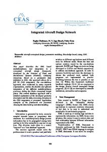
and destination IPs and ports, and protocol; and thus creates static dependencies on those filed values. Such dependencies must be manually configured and maintained and thus are a major source of configuration complexity. Fig. 1c depicts a different design, where hosts in the same VLAN belong to the same department. This design enables expressing filter rules at the level of subnet prefixes, which significantly reduces the number of rules and thus simplifies the filter configuration. However, this design suffers from a different kind of configuration complexity: it requires configuring a large number of VLAN trunk ports, as denoted by the bold lines in the figure. Trunk ports are the switch ports that connect to another switch. Since each VLAN constitutes a separate broadcast domain, it is important to properly constrain broadcast traffic to eliminate unnecessary broadcast traffic for increased performance and security. More specifically, every switch-to-switch link (called “trunk link”) must be configured to only allow traffic of appropriate VLANs. This is achieved by manually configuring the corresponding trunk ports to permit those specific VLANs. VLAN trunk ports configuration is widely considered a major source of complexity, as operators must manually identify and configure the correct set of VLANs to allow for each port. (Readers are referred to Sec.II-A of [32] for a more detailed explanation of trunk ports). Fig. 1d shows a third design. The design still enables expressing filter rules at the subnet prefix level, but also significantly reduces the amount of trunk port configuration by requiring fewer VLAN trunk ports. Furthermore, the IP allocation scheme of this design is better than the previous one as it facilitates prefix aggregation when expressing rules, i.e., it allows aggregating the two original filter rules (“permit 10.0.1/24” and “permit 10.0.2/24”) into a single /23 rule (“permit 10.0.1/23”) as shown. We make two observations from this example. First, for the same target network, there exist multiple designs that are all correct. For our example network, there are at least 6 different designs (three different VLAN grouping schemes coupled with two different address allocation schemes.) However, different designs have different levels of configuration complexity. Second, the complexity of the resulting network is determined by both the VLAN configuration complexity (characterized by the number of trunk ports) and the packet filter complexity (characterized by the number of filter rules). Furthermore, the packet filter design is directly impacted by both the VLAN grouping scheme and the IP address allocation scheme. Thus, a design approach clearly will not work well if it treats VLAN grouping and IP allocation as total independent tasks and ignore their inherent interactions. For example, current topdown design approaches (e.g., [32, 33]) consider VLAN design as an isolated task, and thus they will solely seek to minimize the number of trunk ports without considering how doing so will impact the packet filter design, i.e., they will pick the first design shown in Fig. 1b for our toy example, which is clearly not the best.
in Section 3. It is this unnecessary complexity that this work seeks to expose and minimize. It should be noted that the recent progress in systematic network design owes largely to new abstractions from related work in several areas, including (i) characterization of the designs of production networks (e.g., [22]), (ii) static analysis of network properties (e.g., [21, 35]), and (iii) the formulation of new configuration complexity metrics [7]. 2.3 Software Defined Networking To combat network complexity, researchers have started investigating new software-defined networking (SDN) architectures based on logically centralized controllers and declarative configuration languages (e.g., Frenetic [15]). These approaches have the potential to simplify network design by shifting complexity away from configuration of many individual devices to programming of few centralized controllers. While SDN has shown potential, challenging problems such as the need to update network devices in a consistent fashion [30] must be resolved before it can be widely deployed. More importantly, SDN operators must carry out a similar design task of translating high-level reachability control requirements into flow rules. Since these flow rules will be installed on demand in the Ternary Content Addressable Memory (TCAM) of switches and once installed, checked for each packet passing through, it is desirable to minimize the number of such rules required. In this way, the design methodology and heuristics presented in this paper also apply to an SDN setting, as further discussed in Section 7.
3
An Integrated Design Framework for Reachability Control
We now apply the integrated top-down approach as described in Section 1 to the user reachability control problem. With an illustrative example scenario, we identify the networking elements that are involved in realizing this important design objective, understand the source of configuration complexity of each element, and capture how the designs of individual elements may interact with each other and impact the overall complexity. We then present a framework for achieving an integrated design of user readability control. 3.1 An Illustrative Example Scenario Our example is based on the toy network shown in Fig. 1a. There are two departments: Engineering and Financial. Each department has users in multiple locations as shown. In addition, there is a set of servers. The reachability control policy is that the servers should only be accessed by Financial users. The following design steps are needed to implement the policy: (i) grouping the hosts into VLANs; (ii) assigning subnet addresses to VLANs; and (iii) installing a filter restricting access to the servers. We are given the following design constraints: at most three VLANs can be created; and the available IP blocks are 10.0.1/24, 10.0.2/24 and 10.0.3/24. Fig. 1b illustrates a first possible design, where hosts are grouped into VLANs solely based on their physical locations. Unfortunately, this grouping scheme makes configuring the filter difficult: it is not possible to express the rules at the level of subnet prefixes for VLAN 10 or VLAN 20, because they both contain hosts from both departments. As such, we have to write filter rules at the level of IPs to permit individual Financial hosts, which results in an explosive growth of rules. We note that each packet filter is a sequential collection of filter rules, and each filter rule contains a pattern to be matched against packet headers, and an action (i.e., permit or deny) to be applied to packets whose header matches the corresponding pattern. The pattern part may be configured to match specific values of all or any subset of the five header fields: source
3.2 Elements of Reachability Control and Their Interactions Realizing a host-level reachability control consists of designing the following networking elements: VLAN, IP address allocation, routing, and packet filters. We discuss below the role of each of these elements, their impact on configuration complexity, and their inherent interactions. First, the VLAN design directly determines the number of trunk ports that need to be configured and maintained in the resulting network, a major source of operational complexity. Furthermore, the VLAN design also significantly impacts the packet filter complexity, as it determines how hosts are grouped into subnets. Intuitively, if the VLANs align well with reachability policy boundaries (e.g., 3
!"#$%)'%
!!""!
,-.,/0'
()4(+,'
,3-.,-00'
,/-.,10'
(+)4(-,'
,1-.,20'
(-)4(.,'
!"#$%('%
!!""!
(.)4(5,'
,2-.,30'
!"#$#%"$&'()*+*'''''''''''''''
4#5"#667"#5'()*+*'''''''''''''''
'!"#$#%"$&'*67867*'''''''''''''''
9$%:6+';&+67'''''''''''''''
7(87,)'
!!""
!"#$%&'()' *' !"#$%&'(+,' !"#$%&'(-)' *' !"#$%&'(.,' !"#$%&'/0123,'
!"#$%&'%%
(b) Design #1: Purely location-based VLAN grouping leads to an explosion in the number of filter rules.
(a) The example network to be designed
!"#$%&'%%(&')')&*+,-% !
(5)4(),,'
!"#$%)'% ()'*'*),&-.% 7:(87())'
7(87,)'
7,(87-)'
!!""!
!"#$%+'%% ()'*'*&,&-.% 7;(87())'
7,(879)'
!"#$%.'%%(&')').*+,-% 7-(879)'
79(87:)'
79(87:)'
!"#$%+'% (&')')+*+,-%
7:(87;)'
!"#$%&'()*)*(+,-'.%*"*/'0"#$%&'1234'()5' !"#$%&'()*)*6+,-'.%*"*/'0"#$%&''1234'6)5'
!"#$%&'% ()'*'*+,&-.%
(c) Design #2: This VLAN grouping leads to fewer filter rules but an excessive number of trunk ports. Also, this address allocation scheme does not allow aggregation of filter rules.
!"#$%&'()*)*(+,-'.%*"*/'0"#$%&'1234'()'5'-)6'
(d) Design #3: A better VLAN grouping scheme that reduces the sum of filter rules and trunk ports. Also a better address allocation scheme that facilitates aggregation of filter rules.
Figure 1: multiple designs with different complexity characteristics exist for one network. hosts in the same VLAN are subject to the same policies), then policies may be efficiently expressed at the level of subnet prefixes, resulting in the minimal number of filter rules. On the other hand, if VLANs are ill-aligned with policy boundaries (e.g., a single VLAN contains hosts with completely different policy requirements), then filter rules may have to be expressed at the level of individual IP addresses, leading to a large number of rules.
subnets [33]. Routing design determines the layer-three topology, and thus impacts the number of packet filters needed and where they should be installed.
Second, the IP allocation scheme determines how packet filter rules may be aggregated and thus impacts the number of filter rules in the resulting network. Intuitively, a good IP allocation scheme can minimize the number of filter rules by assigning aggregatable IP blocks to VLANs/subnets that are subject to similar reachability policies, so that a single filter rule can cover multiple subnets by using an aggregated prefix. In contrast, a naive IP allocation scheme that assigns IP prefixes solely based on the physical location of the subnets is not likely to minimize complexity. As another real-world example, we have observed that some operational networks employ an IP allocation scheme that matches the third octet of every subnet prefix address to the corresponding VLAN ID, e.g., VLAN 100 will be assigned prefix x.y.100/24. Such naive approaches treat IP allocation as an isolated design task and try to simplify the allocation scheme itself, but they fail to systematically consider how the IP allocation will impact the aggregation of filter rules.
Scope of this work: We observe that in practice, packet filters are typically only placed at the network edge, i.e., on the gateway routers of subnets. This design pattern has two major benefits. First, it guarantees that traffic to/from a subnet will always be filtered while simplifying the filter placement. That is, it relieves operators from having to find out all the possible layer-three paths between subnets. Second, all policies regarding a particular subnet are implemented in a single location (i.e., its gateway router), which maximizes the opportunity to compress the filter rules through prefix aggregation, and thus simplifies the configuration of filter rules. Given this observation, in this paper we assume that packet filters can only be placed on the gateway routers of subnets. This assumption gives the additional benefit that we no longer need to consider routing design further, since the filter placement is now fixed and independent of the layer-three topology. We do wish to acknowledge that systematic routing design is a challenging research problem on its own. We leave a more comprehensive investigation of designs where filters may be placed anywhere in the network to future work, and focus on VLAN design, IP allocation, and packet filter design in this paper.
Finally, packet filters implement the reachability control policy, and is another major source of configuration complexity. As discussed above, its configuration complexity is impacted by the VLAN design, IP address allocation scheme, and routing design.
Third, the routing design also impacts packet filter complexity. As a principle to ensure the correctness of design, if traffic between two subnets Si and Sj is subject to filtering, then a filter must be placed on every possible layer-three path between the two 4
design and IP allocation scheme are completely independent of each other, i.e., the design choices made in VLAN grouping won’t affect the available design space of the IP allocation scheme, and vice versa. Given this insight, we are able to formulate the design of reachability control as two joint design problems in order to make it more tractable:
3.3 Formulating the Reachability Control Design Problem Following the integrated design methodology described in Section 1, we now present a design framework for reachability control, which integrates the design of the individual elements identified above. In doing so, our goal is to enable the design process to be fully automated, and require only high-level specifications from operators. We first present a new abstraction that facilitates specifying and modeling reachability policy, and then present the framework.
• Joint design of VLANs and packet filters; • Joint design of IP allocation scheme and packet filters.
3.3.1 A New Abstraction for Specifying Reachability Policies
The output of the first joint design includes the VLAN grouping scheme, and an intermediate representation of packet filter rules expressed in terms of individual VLANs and hosts. This intermediate representation of packet filters then becomes part of the input to the second joint design. The output of the second joint design includes the IP allocation scheme, and complete packet filters expressed in terms of IP address blocks. In the next two sections, we formulate and solve the two joint design problems.
An essential input to our framework is the reachability control policies, and it is important to consider how they should be specified. The current “divide-and-conquer” design approach [33] requires reachability policies to be specified at the VLAN/subnet level, i.e., it requires operators to specify a reachability matrix where each cell (i, j) denotes the reachability between VLAN i and VLAN j. This abstraction works for the “divide-and-conquer” approach which assumes that the VLAN design has already been completed before designing packet filters. However, it does not work for our approach which integrates the design of VLANs and packet filters, i.e., our framework cannot use such a VLAN-level reachability matrix as input because VLANs themselves are to be determined by the solution. In addition, we believe that the VLAN-level reachability matrix is too low level as a policy abstraction, and it is tedious for operators to specify reachability policy using it. In this work, we introduce a new abstraction for specifying reachability policy: a reachability matrix at “user role” level. We define a user role as a logical category that a set of users or servers belong to. Example user roles include faculty users, Computer Science users, financial servers, etc. Note that a user may have multiple roles, e.g., a CS professor can have both roles of CS users and faculty users. Each cell (i, j) of the reachability matrix specifies reachability policy between a user role i and another user role j. The advantage of this abstraction is that it allows policies to be specified at a high level and independent of any design details.
4
We first present models for formulating the joint design problem, and then develop heuristics for solving the formulated problem. 4.1 Formulating the Joint Design Problem This design task is to map hosts to a set of VLANs and to derive packet filter rules expressed in terms of individual VLANs and hosts. There are several important considerations in doing so, as we detail below. VLAN count: The total number of VLANs that can be created in the design is determined by the hardware used in the network. This is because each VLAN runs its own instance of spanning tree, which consumes the memory and CPU resource of the switches. For example, a Cisco Catalyst 2950 switch can only support up to 64 spanning tree instances [11]. To model this constraint, we simply assume that operators will specify the maximum number of VLANs that can be created, which is denoted by N . VLAN size: A VLAN becomes a separate subnet at layer three, and thus the number of hosts that a VLAN can have is bounded by the size of the IP address block assigned to the corresponding subnet (assuming NAT is not used). For example, it is a common practice to limit the maximum size of a VLAN to that of a /24 subnet, i.e., at most 254 hosts. We assume the operators will specify the maximum VLAN size, denoted by MAX-VLAN-SIZE. Correctness criteria: To ensure the correctness of the design, the following two conditions must be satisfied. First, the given reachability policies must be correctly implemented through packet filters. Second, all hosts in the same VLAN must have full reachability toward each other, since they are all in the same broadcast domain. Configuration complexity: This design will determine the VLAN configuration complexity Cv (i.e., the total number of VLAN trunk ports in the resulting network). Further, it will also impact the packet filter configuration complexity. Note that the filter rules generated by this design are expressed in terms of individual VLANs and hosts. The VLANs and hosts will be assigned IP addresses in the second joint design, and thus the filter rules could be further aggregated when converted to the IP representation in that design. Thus, we model the total configuration complexity introduced by ′ this design (denoted by Ctotal ) as follows:
3.3.2 Formulating Reachability Control Design We formulate the design problem of reachability control as follows. We assume we are given the physical topology of the network, and the set of users/servers and their network locations. For each user/server, we are given its user roles. We are given the reachability matrix at the user-role level as described above. In addition, we are given the maximum number of VLANs that can be created (denoted by N ), and the available IP blocks. The design framework includes tasks of (i) mapping the set of users to at most N VLANs, (ii) assigning IP blocks from the available IP space to the created VLANs, and (iii) configuring packet filters to enforce the reachability policies. Our goal is to minimize the total configuration complexity of the resulting network. As discussed above, the configuration complexity (denoted as Ctotal ) includes both VLANrelated complexity (denoted by Cv ), measured by the number of trunk ports, and filter-related complexity (denoted by Cf ), measured by the number of filter rules. Formally, we model the total configuration complexity as: Ctotal = Wv ∗ Cv + Wf ∗ Cf
Joint Design of VLANs and Packet Filters
(1)
where Wv and Wf are the weight factors given to the two complexity categories, and can be customized by operators. For example, if the operators of a network consider VLAN trunk ports more difficult to configure and maintain than filter rules, they can assign Wv a higher value than Wf . We notice that, while the VLAN grouping scheme and the IP allocation scheme both impact the packet filter complexity, VLAN
′ Ctotal = Wv ∗ Cv + Wf ∗ Cf′
(2)
Wv , Wf and Cv have been defined for Equation (1). Cf′ is the configuration complexity of the packet filters generated by this design task, measured as the total number of filter rules. Clearly Cf′ ≥ Cf 5
smaller VLANs. If so, we will execute the partitioning, and iteratively evaluate for the resulting two smaller VLANs. We repeat ′ by this step for every VLAN until we cannot further reduce Ctotal partitioning existing VLANs. Our insight for this step is as follow. On one hand, partitioning a VLAN that has a large span could ′ as it could significantly reduce the number potentially reduce Ctotal of trunk ports (i.e, Cv ). Consider V4 (CS-Faculty policy group) in Fig. 2b as an example. By partitioning it into two smaller VLANs, i.e., the new V4 and V8 in Fig. 2c, we eliminate the need for any trunk port for this VLAN, and thus reduce Cv . On the other hand, ′ as it partitioning a VLAN could also potentially increase Ctotal could lead to more filters and/or filter rules required, i.e., an increase in Cf′ . There are two reasons for this. First, after the partitioning it may be necessary to install a new packet filter to protect a newly created VLAN. For example, in Fig. 2c there is a new packet filter that protects the newly created V8, which introduces 6 new rules. Second, it may be necessary to add additional rules in the existing filters, to permit a newly created VLAN. For example, in Fig. 2c a rule “permit V8” is added to four existing filters. More specifically, we employ the K-means clustering algorithm (with K=2) to decide how a VLAN should be partitioned into two, such that the reduction in Cv is maximized. In configuring the clustering algorithm, we let each host in the VLAN be a node, and the distance between two nodes be the length of the shortest layer-two path between the corresponding hosts. The clustering algorithm then groups nearby hosts into the same VLAN and thus minimizes the need of trunk ports. For our running example, we find that by partitioning the old VLAN V4 in Fig. 2b into two smaller VLANs V4 and V8 in fig.2c, we reduces Cv (i.e., the number of trunk ports) by 12, but increases Cf′ (i.e., the number of filter rules) by 10. As we assume Wv = Wf = 1, the total complexity is reduced by 2, according to Equation (2). Hence, we execute the partitioning since it is beneficial to do so. We also find that it is not beneficial to partition any other VLAN. Fig. 2c shows the resulting design after this step.
as the joint design of IP allocation and packet filters may further reduce the number of filter rules through prefix aggregation. Now we can formally formulate this joint design problem as: ′ Minimize: Ctotal Subject to: - the correctness criteria, and - the constraints on VLAN number and size.
4.2 Heuristic for Solving the Joint Design Problem We present the details of our heuristic that works in a step-by-step fashion. For ease of understanding, we use a running example to illustrate the various algorithmic operations. The example network setup is shown in Fig. 2a. There are eight user roles: Biology, Computer Science, IT, Faculty, Students, managers, operators, and servers. The reachability policies are also shown in the graph. We are given that N = 6, and MAX-VLAN-SIZE = 254. For simplicity, we assume that the operator has chosen to set Wv = Wf = 1. 4.2.1 Step 1: Map Policy Groups to VLANs As illustrated in Section 3.1, it is often desirable for a VLAN to contain hosts subject to the same reachability policy, because doing so enables filter rules to be written at the level of an entire VLAN. To capture this insight in the design process, we leverage the abstraction of “policy groups” introduced by recent works [7, 31] including our own for network modeling. A policy group abstracts the set of hosts that are (i) subject to the same reachability policy towards other hosts and (ii) have full reachability among themselves. Clearly the set of policy groups forms a partition of all hosts. It is easy to see that a policy group is an atomic unit in deriving filter rules, i.e., if a packet filter allows traffic from one host in a policy group, it must also allow traffic from all the other hosts of the same policy group. Thus, the use of policy groups in the design process simplifies the reasoning of reachability control by allowing us to reason about groups of hosts together instead of individual ones. We believe the set of policy groups can be straightforwardly derived from the inputs of user roles and the role-level reachability matrix, but omit the details due to lack of space. As a reasonable starting point of the design, we initially let each policy group become a separate VLAN. We then derive the filter rules. As mentioned in Sec.3.2, we have assumed that packet filters can only be placed on the gateway routers of the VLANs to be protected. Thus the filter rules can be determined in a straightforward way: for each VLAN, the corresponding packet filter permits all other VLANs (i.e., policy groups) that can communicate with this VLAN, according to the reachability matrix. We assume an implicit deny in the end of a packet filter, following the vendor convention. Filters that simply permit all traffic are omitted. Fig. 2b illustrate the design after this step. Seven policy groups are identified straightforwardly from the inputs: CS faculty (shown as CS-F on graph) which resides in two different locations, CS students (CS-S), Biology faculty (Bio-F), Biology students (Bio-S), IT managers (IT-M), IT operators (IT-O) and servers (SVR). Each policy group has been placed in a separate VLAN. For example, the entire CS-Faculty policy group becomes VLAN V4. The corresponding VLAN trunk ports to be configured are shown by the bold links connecting those ports. The packet filters are also shown, and as expected all filter rules are expressed at the VLAN level. Finally, the amount of configuration complexity in terms of filter rules and trunk ports after this step is also shown.
4.2.3
Step 3: Partition VLANs with Too Many Hosts
This step ensures that the constraint on VLAN size is met. It checks each VLAN in the current design to see whether it contains more hosts than the specified MAX-VLAN-SIZE. If so, it again uses the K-means clustering algorithm described in the previous step to partition the VLAN into two. This process iterates until all VLANs have been reduced to a size no larger than the MAX-VLAN-SIZE. For our running example, Since none of the VLANs contains more than 254 hosts, this step will not partition any VLAN. 4.2.4
Step 4: Selectively Combine Multiple VLANs
This step has two purposes: further reducing the total complexity ′ Ctotal , and also ensuring that the constraint on the VLAN count is met. It achieves both by selectively combining pairs of VLANs in an iterative process as described below. For every eligible pair of VLANs, the heuristic evaluates the complexity impact of combining them. A pair of VLANs is eligible to be combined if (i) the sum of the hosts in both VLANs is not greater than MAX-VLAN-SIZE, and (ii) the hosts in both VLANs have full reachability toward each other. For every eligible VLAN ′ pair, we calculate the potential change in Ctotal if the two were combined into a single new VLAN. We then select the pair with ′ to execute the combining. We the maximum reduction in Ctotal repeat this process until the following two conditions are both met: • The total number of VLANs is not greater than N (i.e., the maximum number of VLANs that can be created); and, ′ • It is not possible to further reduce Ctotal by combining any more eligible pair of VLANs.
4.2.2 Step 2: Selectively Partition VLANs with Large Span For each VLAN created in Step 1, we now evaluate whether it is ′ ) to partition it into two beneficial (i.e., leading to smaller Ctotal 6
• !"#$#%&'($"%&)*+,"-(."#/%"012" • 3#$4"%&)*"(/$56%&+"7#$65*8" 4.+*+"#/%"+*6%&/*"4.+*+2" • 9/":;"$&/*&%,?%86BEF%G,68CD%(% 4567+8%9'% 4567+8%9.% % 4567+8%93% % 4567+8%9=% 4567+8%9?5A" 7-:"
D89"
DF"
DF"
8"
• DF"+J#*&K"LMM)(ML'("N4@" 6A9"
D78"
DF"
DF"
HKL" H78"
DFG" D78"
D