IEEE TRANSACTIONS ON VERY LARGE SCALE INTEGRATION (VLSI) SYSTEMS, VOL. 6, NO. 1, MARCH 1998
141
Minimizing the Complexity of SRT Tables Stuart F. Oberman, Member, IEEE, and Michael J. Flynn, Life Fellow, IEEE
Abstract—This paper presents an analysis of the complexity of quotient-digit selection tables in SRT division implementations. SRT dividers are widely used in VLSI systems to compute floating-point quotients. These dividers use a fixed number of partial remainder and divisor bits to consult a table to select the next quotient-digit in each iteration. This analysis derives the allowable divisor and partial remainder truncations for radix 2 through radix 32, and it quantifies the relationship between table parameters and the complexity of the tables. Several techniques are presented for further minimizing table complexity. By mapping the tables to a library of standard-cells, delay and area values were measured and are presented for table configurations through radix 32. Several conclusions are drawn based on this data which impacts optimized SRT divider designs. Index Terms— Computer arithmetic, floating point, performance tradeoffs, quotient-digit selection, SRT division, table complexity.
I. INTRODUCTION
I
N recent years computer applications have increased in their computational complexity. High-speed floating-point hardware is a requirement in many VLSI systems to meet these increasing demands. An important component of the floating point unit is the divider. There are many methods for designing division hardware, including quadratically converging algorithms, such as Newton–Raphson, and linear converging algorithms, the most common of which is SRT [15]. SRT division computes a quotient one digit at a time, with an iteration time independent of the operand length. The theory of SRT division is discussed thoroughly in Atkins [1], Ercegovac [7], Robertson [17], and Tan [20]. Several SRT implementations have been reported, including radix 2 dividers by Knowles [11], Kuninobu [12], Vandemeulebroecke [22], and Zuras [23], radix 4 by Birman [3] and Fandrianto [8], radix 8 by Fandrianto [9] and Prabhu [16], and radix 16 by Carter [5] and Taylor [21]. SRT dividers with simplified quotient-digit selection using operand range restriction have been presented in Ercegovac [6], Montuschi [14], and Srinivas [18]. Harris [10] discusses detailed algorithmic and circuit tradeoffs in SRT divider design. There are many performance and area tradeoffs when designing an SRT divider. One metric for comparison of different designs is the minimum required truncations of the divisor and partial remainder for quotient-digit selection. Atkins [1] and Robertson [17] provide such analyzes of the divisor Manuscript received November 12, 1995; revised August 20, 1997. This work was supported by the U.S. National Science Foundation under Grant MIP93–13701. The authors are with the Computer Systems Laboratory, Stanford University, Stanford, CA 94305 USA (e-mail:
[email protected] and
[email protected]). Publisher Item Identifier S 1063-8210(98)01320-1.
and partial remainder precisions required for quotient-digit selection. Burgess and Williams [4] present in more detail allowable truncations for divisors and both carry-save and borrow-save partial remainders. However, a more detailed comparison of quotient-digit selection complexity between different designs requires more information than input precision. This paper analyzes in detail the effects of algorithm radix, redundancy, divisor and partial remainder precision, and truncation error on the complexity of the resulting table. Complexity is measured by the number of product terms in the final logic equations, and the delay and area of standardcell implementations of the tables. These metrics are obtained by an automated design flow using the specifications for the quotient-digit selection table as input, a Gray-coded PLA as an intermediate representation, and an LSI Logic 500 K standard-cell implementation as the output. This paper also examines the effects of additional techniques such as tablefolding and longer external carry-assimilating adders on table complexity. Using the methodology presented, it is possible to automatically generate optimized high radix quotient-digit selection tables. The remainder of this paper is organized as follows: Section II presents the theory of SRT division; Section III discusses the implementation of SRT tables; Section IV presents our methodology for implementing the quotientdigit selection tables; Section V presents the results; and Section VI is the conclusion. II. THEORY
OF
SRT DIVISION
SRT division belongs to the digit recurrence class of division algorithms. Digit recurrence algorithms use subtractive methods to calculate quotients one digit per iteration. Digit recurrence algorithms can be divided into restoring and nonrestoring division. Restoring division is similar to the familiar paper and pencil division. When dividing two digit numbers, the division can require up to 2 additions or subtractions. Nonrestoring division algorithms eliminate the additions. restoration cycles, and thus only require up to This can be accomplished by allowing negative values of the quotient as well as positive values. In this way, small errors in one iteration can be corrected in subsequent iterations. A. Recurrence In SRT division, the quotient can be computed as follows: dividend divisor This expression can be rewritten as dividend
1063–8210/98$10.00 1998 IEEE
divisor
remainder
142
IEEE TRANSACTIONS ON VERY LARGE SCALE INTEGRATION (VLSI) SYSTEMS, VOL. 6, NO. 1, MARCH 1998
such that remainder
divisor
ulp
and sign(remainder)
sign(dividend)
where the input operands are given by dividend and divisor, and remainder. The precision of the and the results are quotient is defined by the unit in the last position (ulp), where 1, and for a fractional quotient for an integer quotient ulp using a binary representation ulp 2 , assuming an digit quotient. The radix of the algorithm, typically chosen to be a power of 2, determines how many quotient bits are 2 . Accordingly, a retired in each iteration, such that iterations to compute an radix algorithm requires digit quotient. The following recurrence is used at every iteration: dividend divisor
(1) (2)
is the partial remainder, or residual, at iteration . where In each iteration, one digit of the quotient is determined by the quotient-digit selection function SEL
divisor
(3)
to be bounded, In order for the next partial remainder the value of the quotient-digit is chosen such that divisor
only power of two radices are considered. Assuming the same quotient precision, the number of iterations of the algorithm required to compute the quotient is reduced by a factor when the radix is increased from to . For example, a radix 4 algorithm retires 2 bits of quotient in every iteration. Increasing to a radix 16 algorithm will allow for retiring 4 bits in every iteration, for a 2X reduction in latency. This reduction does not come for free. As the radix increases, the quotientdigit selection becomes more complex. Since the quotient-digit selection is typically on the critical path of the algorithm, even though the number of cycles may have been reduced due to the increased radix, the time per cycle may have increased. As a result, the total time required to compute an bit quotient may not be reduced by the factor . Accordingly, the radix is a fundamental parameter in determining the complexity of the quotient-digit selection table. C. Choice of Quotient Digit Set A range of digits is decided upon for the allowed values of the quotient in each iteration. The simplest case is where, for radix , there are exactly allowed values of the quotient. However, it is often desirable to utilize a redundant digit set which simplifies the quotient-digit selection table, thereby increasing the performance of the divider. Such a digit set can be composed of symmetric signed-digit consecutive integers, where the maximum digit is . In particular
(4)
The final quotient is the weighted sum of all of the quotientdigits selected throughout the iterations, such that:
The redundancy of a digit set is determined by the value of the redundancy factor , which is defined as (6)
final
(5)
As can be noted from (1) and (2), each iteration of the recurrence comprises the following steps: by the quotient-digit 1) determine next quotient-digit selection function; ; 2) generate the product from to form the next 3) subtract partial remainder. Each of these components can contribute to the overall cost and performance of the algorithm. To reduce the time for partial remainder computation, intermediate partial remainders are often stored in a redundant representation, either carry-save or signed digit form. Then, the partial remainder computation requires only a full adder delay, rather than a full width carrypropagate addition. The rest of this paper is concerned with the quotient-digit selection component.
For all partial remainders to be bounded when a redundant quotient digit set is used, the value of the quotient-digit must be chosen such that divisor
(7)
B. Choice of Radix
The calculation of the final quotient using a redundant quotient-digit set involves either a full carry propagate addition to subtract the negative quotient-digits from the positive quotient-digits at the completion of the iterations, or the use of on-the-fly quotient conversion techniques [7]. After the redundancy factor is chosen, it is possible to derive the quotient-digit selection function. To guarantee that the shifted partial remainder remains bounded for all valid quotient-digits and divisor, expressions for the quotient-digit selection intervals must be computed. A selection interval is the region in which a particular quotient-digit can be safely chosen such that the shifted partial remainder will remain bounded. The expressions for the selection intervals are given by
The fundamental method of decreasing the overall latency (in machine cycles) of the SRT algorithm is to increase the radix of the algorithm. By choosing the radix to be a power of two, the product of the radix and the partial remainder can be formed by shifting. Accordingly, throughout this study,
where ( ) is the largest (smallest) value of such that to be chosen and still keep the next it is possible for shifted partial remainder bounded. The continuity condition
OBERMAN AND FLYNN: MINIMIZING THE COMPLEXITY OF SRT TABLES
143
The bits in the truncated estimate can be divided into integer bits and fractional bits, such that . The table can take as input the partial remainder estimate directly in redundant form, or it can use the output of a short carry-assimilating adder that converts the redundant partial remainder estimate to a nonredundant representation. The use of an external short adder reduces the complexity of the table implementation, as the number of partial remainder input bits are halved. However, the delay of the quotient-digit selection function increases by the delay of the adder. It is not possible to determine the optimal choices of and analytically, as several factors are involved in making these choices. However, it is possible to determine a lower bound on using the continuity condition and the fact that the next partial remainder must remain bounded (9) (10)
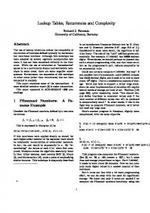
Fig. 1. P–D diagram for radix 4.
requires that for all valid values of , it must be possible to select at least one quotient digit [7]. This is expressed mathematically as (8) is represented by a maximum of bits, the term Because is the resolution of the partial remainder. The P–D diagram is a useful visual tool when designing a quotient-digit selection function. It has as axes the shifted partial remainder and the divisor. The selection interval bounds and are drawn as lines starting at the origin with slope and , respectively. A P–D diagram is shown in 4 and 2. The shaded regions are the Fig. 1 with overlap regions where more than one quotient-digit may be selected. III. IMPLEMENTING SRT TABLES
Because the divisor is IEEE normalized with a leading one, fractional bits are required as input only the leading to the table. The next quotient-digit can then be selected by entry lookup table, using these estimates to index into a implemented either as a PLA or random logic. Assuming a nonredundant two’s complement partial remainand der, the estimates have nonnegative truncation errors for the divisor and shifted partial remainder estimates, respectively, where (11) (12) Thus, the maximum truncation error for both the divisor and the nonredundant shifted partial remainder estimates is strictly less than 1 ulp. For a redundant two’s complement partial remainder, the truncation error depends upon the representation. For a carrysave representation, the sum and carry estimates each has nonnegative truncation error , assuming that both the sum and carry estimates are represented by the most significant has bits of their true values. The resulting estimate truncation error
A. Divisor and Partial Remainder Estimates To reduce the size and complexity of the quotient-digit selection table for a given choice of and , it is desirable to use as input to the table estimates of the divisor and shifted partial remainder which have fewer bits than the true values. Assuming IEEE floating-point compliance, the input . Therefore, bit operands are in the range 2 . operands normalized to this range have an ulp Further, a leading integer one can be assumed for all divisors, and the table only requires fractional divisor bits to make a quotient-digit selection. The shifted partial remainder, though, requires both integer and fractional bits as inputs to the and divisor can table. The shifted partial remainder and using the most be approximated by estimates and the most significant bits of . significant bits of
(13) Thus, the maximum truncation error for an estimate of a carry–save shifted partial remainder is strictly less than 2 ulps. From this discussion, the number of integer bits in can be determined analytically. Using the general recurrence for SRT division, the maximum shifted partial remainder is given by (14) For IEEE operands (15) As previously stated, for a carry–save two’s complement representation of the partial remainder, the truncation error
144
IEEE TRANSACTIONS ON VERY LARGE SCALE INTEGRATION (VLSI) SYSTEMS, VOL. 6, NO. 1, MARCH 1998
is always nonnegative, and therefore the maximum estimate of the partial remainder is
The minimum estimate of the partial remainder is
Accordingly,
can be determined from (16) (17)
B. Uncertainty Regions By using a redundant quotient-digit set, it is possible to correctly choose the next quotient-digit even when using the and . Due to the truncation error in truncated estimates the estimates, each entry in the quotient-digit selection table has an uncertainty region associated with it. For each entry, it is necessary for all combinations of all possible values and to lie in the same represented by the estimates selection interval. For a carry-save representation of the shifted partial remainder, this involves calculating the maximum and minimum ratios of the shifted partial remainder and divisor, and ensuring that these ratios both lie in the same selection interval if
valid values of and for a given and , it is necessary to entries in the calculate the uncertainty regions for all table. If all uncertainty regions are valid for given choices of , , and , then they are valid choices. C. Reducing Table Complexity
(18)
ratio if if
(19)
ratio if
Fig. 2. Uncertainty regions due to divisor and partial remainder estimates.
.
If an uncertainty region is too large, the maximum and minimum ratios may span more than one selection interval, requiring one table entry to return more than one quotientdigit. This would signify that the estimate of the divisor and/or the shifted partial remainder has too much truncation error. Fig. 2 shows several uncertainty regions in a radix 4 P–D plot. Each uncertainty region is represented by a rectangle whose height and width is a function of the divisor and partial remainder truncation errors. The value of ratio corresponds to the upper left corner of the rectangle, while corresponds to the lower right corner. In this figure, ratio the four valid uncertainty regions include a portion of an overlap region. Further, the lower right uncertainty region is fully contained within an overlap region, allowing the entry corresponding to that uncertainty region to take on the quotient-digits of either zero or one. The other three valid uncertainty regions may take on only a single quotient-digit. The upper left uncertainty region spans more than an entire overlap region, signifying that the corresponding table entry, and as a result the entire table, is not valid. To determine the
The size of the table implementation can be reduced nearly in half by folding the table entries as suggested in Fandrianto [8]. Folding involves the conversion of the two’s complement to signed-magnitude, allowing the same representation of table entries to be used for both positive and negative values . This reduction does not come for free. First, it of requires additional logic outside of the table, such as a row of XOR gates, to perform the representation conversion, adding external delay to the quotient digit selection process. Second, it may place further restrictions on the table design process. When a carry-save representation is used for and a truncated estimate is used to consult the table, the truncation error is always nonnegative, resulting in an asymmetrical table. To guarantee the symmetry required for folding, additional terms must be added to the table, resulting in a less than optimal implementation. A complexity-reducing technique proposed in this study is to minimize . As presented previously, when using an external carry-assimilating adder for a truncated two’s complement carry-save partial remainder estimate, the maximum is approximately . This error can be furerror ther reduced by using fractional bits of redundant partial , but remainder as input to the external adder, where only using the most significant fractional output bits of the adder as input to the table. The maximum error in the output of the adder is (20)
OBERMAN AND FLYNN: MINIMIZING THE COMPLEXITY OF SRT TABLES
145
Fig. 3. Design flow.
IV. EXPERIMENTAL METHODOLOGY The focus of this paper is to quantitatively measure the tradeoffs between the parameters , , , , , , and the complexity of the logic equations, measured by the number of product terms, as well as the complexity of the resulting random logic implementations of the tables, as measured by implementation delay and area. The design flow of Fig. 3 was used to automatically generate quotient-digit selection tables in random logic. In this study, a carry-save two’s complement representation is used for the partial remainder in all tables. A. TableGen
Fig. 4. Components of an SRT divider.
Then, by using bits of the adder output, the maximum error for the input to the table is
(21) , the error remains approximately . For the case is reduced, conHowever, by increasing , the error verging toward the error for a nonredundant partial remainder . Reducing the truncation error which is approximately decreases the height of the uncertainty region in the PD diagram. This has the effect of allowing more of the entries’ uncertainty regions to fully fit within overlap regions, increasing the flexibility in the logic minimization process, and ultimately reducing the complexity of the final table. A block diagram illustrating the various components of an SRT divider is shown in Fig. 4.
The program TableGen performs the analytical aspects of the quotient-digit selection table design. This program takes the table parameters as input, and it produces the unminimized PLA entries necessary to implement the table. First, all of the uncertainty regions for all entries in the table are computed. TableGen determines whether or not the choice of input parameters results in a valid table design. If the table is valid, it then computes the allowable quotient-digits for each entry in the table, based upon the size of the uncertainty region. The allowable quotient-digits are then written in PLA form for all possible shifted partial remainder and divisor pairs. To allow for the greatest reduction in the complexity of the table implementations, it is proposed in this study to use a Gray code to encode an entry’s allowable quotient-digits. In a Gray encoding, neighboring values only differ in one bit position [2]. This allows for the efficient representation of multiple allowable quotient-digits in the PLA output, while bits. The Gray-coding of the digits still only requiring is recommended to ensure that given a choice between two allowable quotient-digits in an overlap region, the optimal choice can be automatically determined that will result in the least complex logic equations. outputs of the table which Accordingly, there are are the bits of the encoded quotient-digit. Table entries where and ratio are both greater than are unreachratio able entries. Thus, their outputs are set to don’t care. An 4 and 3 is shown in example of Gray-coding for Table I. In this example, a value of implies a don’t care. Because the table stores digits in encoded form, all tables in this study require an explicit decoder to recover the true quotient-digit and select the appropriate divisor multiple. This results in the addition of a decoder delay into the critical path. However, since all tables in this study use the same encoding, this is a constant delay that only grows as the log of the radix. Alternatively, the quotient-digits could be stored in an unencoded form, removing the need for the decoder. Optimal logic minimization becomes a much more difficult problem for unencoded digits.
146
IEEE TRANSACTIONS ON VERY LARGE SCALE INTEGRATION (VLSI) SYSTEMS, VOL. 6, NO. 1, MARCH 1998
TABLE I GRAY ENCODING FOR MAXIMALLY REDUNDANT RADIX 4
TABLE III RADIX 2
TABLE IV RADIX 8
TABLE II RADIX 4 TRADEOFFS
TABLE V RADIX 16
Espresso is used to perform logic minimization on the output PLA. This produces a minimized PLA and the logic equations representing the PLA in sum of products form. The number of product terms in these expressions is one metric for the complexity of the tables. To verify the correctness of the tables, an SRT divider was simulated using a DEC Alpha 3000/500 with the minimized logic equations as the quotient-digit selection function. After each table was generated, the equations were incorporated into the simulator. Several thousand random and directed IEEE double precision vectors were used as input to the simulator, and the computed quotients for each table were compared with the computed results from the Alpha’s internal FPU. B. Table Synthesis To quantify the performance and area of random logic implementations of the tables, each table was synthesized using a standard-cell library. The Synopsys Design Compiler [19] was used to map the logic equations describing each table to an LSI Logic 500 K 0.5 m standard-cell library [13]. In the mapping stage, low flattening and medium mapping effort options were used. However, area was always sacrificed to reduce the latency. In order to minimize the true critical path of the tables, the input constraints included the late arrival time of all partial remainder inputs due to an external carryassimilating adder. Area and delay estimates were obtained from a Design Compiler prelayout report. Each delay includes intrinsic gate delay, estimated interconnect wire delay, and the input load of subsequent gates. All delays were measured using nominal conditions. Each area measurement includes both cell and estimated routing area. The delay and area are reported relative to those for a base radix 4 table, which is Gray-coded with 3, 3, 3, and 3. The base table requires 43 cells and has a delay of 1.47 ns.
The results are presented in Tables II–VI. The complexity of the tables is measured by the number of product terms, the relative delay, and the relative area for each configuration. The terms result contains both the number of product terms for each output of the table, as well as the total number of terms in the table. For a given radix , there are exactly outputs of the table. Accordingly, this column first lists the outputs. Because there number of terms in each of the is usually some internal sharing of product terms, the last number, which is the total number of unique terms required to implement the table, is typically less than the sum of the terms for the individual outputs. The reported delay is the worst-case outputs, typically corresponding to delay of any of the the output which has the highest number of product terms. V. RESULTS A. Same Radix Tradeoffs Table II shows the results for various radix 4 configurations. The parameters varied in this table are 1) the number of bits
OBERMAN AND FLYNN: MINIMIZING THE COMPLEXITY OF SRT TABLES
TABLE VI RADIX 32
versus bits, 2) folding, 3) method of choosing values in the overlap regions, and 4) the amount of redundancy. The first entries examine the effects of using bits of the redundant partial remainder into the short CPA outside of the table, while only using bits of the adder output as input to the table. Simply extending the CPA by one bit reduces the delay by 12% and area by 7%. Extending the CPA by two bits reduces the delay by 16% and area by 9%. In the limit where and a full-mantissa carry propagate addition is required, the delay and area are both reduced by 23%. This demonstrates that increasing the width of the CPA by as little as one or two bits can reduce the complexity of the table. The next two entries demonstrate the effects of using folded 3 and 4, tables. For both tables, it is assumed that which matches the format of the table suggested in Fandrianto [8]. The use of only a two’s complement to sign-magnitude converter yields the first folded table, which achieves an additional delay reduction of 10% and an additional area 3 4 table without folding. reduction of 30% over the This introduces a serial delay of an XOR gate external to the delay of the table. When the sign-magnitude converter is combined with a “t-bit converter”, which further constrains the range of input values to the table, the delay is reduced relative to the simple folded table by an additional 10%, and the area is reduced by an additional 12%. This converter introduces the serial delay of an OR gate external to the table. These results show that folding can reduce the size and delay of the table. However, the delay of the required external gates must be considered for the overall design. If the sum of the XOR
147
and OR gate delays is less than 29% of the base table delay, table folding can result in a net decrease in delay. The parenthesized values for these two entries represent the delay and area of table when the required external gates are included in the calculation. When the XOR gates are implemented in this standard cell technology, they account for about 66% of the unfolded table delay. This is in part due to the more complex functionality of the XOR gate relative to the other utilized gates. It is also due to the high fanout of the sign of the partial remainder which must drive the select signals of 5 XOR gates. The total delay of the folded table with the row of XOR gates is 49% greater than the unfolded table, but the area is reduced by 8%. When the “t-bit converter” is implemented through the addition of a row of OR gates driven by the MSB of the ones-complemented partial remainder, the total delay increases by 80% over the unfolded table, but the area is reduced by 10%. Thus, in this technology, the use of either table-folding technique results in higher overall delay, as the added delay from the external gates is greater than the corresponding reduction in table delay. However, these techniques do allow for a small reduction in total area. Different encodings of the quotient-digits can change the complexity of the tables. The lower bound for delay and area of the table is achieved when each boundary between two consecutive quotient-digits is individually encoded. The recovery of the unencoded quotient-digit may require a large external decoder. When using such a “line” encoding scheme, again with and , the delay and area are reduced by 5 and 8%, respectively, relative to the base Grayand . However, the coded table, also with external decoder delay grows linearly with increasing for line encoding, while only growing as the log of for Graycoding. Another common encoding scheme always uses the highest digit whenever a choice is available between two consecutive quotient-digits. This is represented in the table as “choose highest” encoding. While simplifying the table generating process, this method increases the resulting table delay by 19% and area by 32% over the base table. Thus, this study shows that Gray-coding of the quotient-digits achieves delays and areas approaching the lower bound of line encoding, while requiring less complex external decoders. The redundancy of the digit set has an impact on table complexity. The final entries in the table are for maximally . For an implementation redundant radix 4 tables, with , the delay and area are reduced by 20 and with , requiring a 46%, respectively. When increases to full mantissa-width CPA, the delay is further reduced by 21% and the area by 44%. These results show that if the hardware is available to generate the 3 divisor multiple, the iteration time can be reduced by over 20%, due to the reduction in table complexity and length of the external short CPA. Table III shows the complexity of a basic radix 2 table. This table can be implemented by a single three-input gate, as it only has 3 PLA terms, which can be contrasted with the 25 terms in the baseline radix 4 table. The resulting delay is 65% less than the base radix 4 table, while 93% less area is required. Accordingly, the radix 2 table is 2.86 times faster
148
IEEE TRANSACTIONS ON VERY LARGE SCALE INTEGRATION (VLSI) SYSTEMS, VOL. 6, NO. 1, MARCH 1998
than the base radix 4 table, and 2.40 times faster than a radix 4 table. B. Higher Radix Tables IV–VI show the complexity for tables that directly implement radix 8, 16, and 32, respectively. The allowable choices of , , and determined in this study correspond with the results presented in [4] for radix 8 and 16. In our study, we extend the allowed operand truncations to radix 32. For radix 16 and radix 32, the minimally redundant configurations required 20 or more inputs to the table. Due to computational constraints, table optimization was limited to configurations containing fewer than 20 inputs. Those configurations where optimization was infeasible are denoted with a dagger in the tables. For a given choice of radix and redundancy, there exists more than one possible table design. As discussed previously, a minimum number of divisor estimate bits is required as input for a given configuration. This corresponds to a maximum number of partial remainder bits that need be used. However, it is possible to trade an increase in divisor bits for a reduction in the number of partial remainder bits. This might initially seem desirable, as the partial remainder bits must first be assimilated in an external adder, adding to the overall iteration time. By using a fewer number of partial remainder bits in the table, the external adder can be smaller, reducing the external delay. However, for carry-save partial remainders, the is greater maximum partial remainder truncation error than the maximum divisor truncation error . By tradingoff fewer partial remainder bits for more divisor bits, the height of the uncertainty region increases at approximately twice the rate at which the width of the region decreases. As a result, the overall uncertainty region area increases as fewer partial remainder bits are used. This result can be seen quantitatively in Tables IV–VI. For any given choice of radix and redundancy, the use of the maximum number of divisor bits and minimum number of partial remainder bits results in the largest number of total product terms, and typically the largest delay and area. As the number of divisor bits is reduced and the number of partial remainder bits increased, the number of product terms, the delay, and the area are all typically reduced. This study confirms that as the radix increases, the complexity of the tables also increases. Fitting the average area at a given radix to a curve across the various radices determines that the area increases geometrically with increasing radix: Area
(22)
for radix , where this area is the table area relative to that of the base radix 4 divider. Similar analysis of average delay demonstrates that table delay increases only linearly with an increase in the number of bits retired per cycle. Increasing the radix of the algorithm reduces the total number of iterations required to compute the quotient. However, to realize an overall reduction in the total latency as measured in time, the delay per iteration must not increase at the same rate. Thus, to realize the performance advantage of a higher radix divider,
it is desirable for the delay of the look-up table to increase at no more than the rate of increase of the number of bits retired per cycle. For radix 8, the delay is on the average about 1.5 times that of the base radix 4 table. However, it can require up to 10 times as much area. While radix 16 tables have about two times the base delay, they can require up to 32 times the area. In the case of radix 32, it was not even possible to achieve a delay of 2.5 times the base delay, the maximum desired delay, with actual delays between 3.5 and 4.7. The area required for radix 32 ranges from 57 to 141 times the base area. These results show that radix 16 and 32 are clearly impractical design choices, even ignoring practical implementation limitations such as generating all divisor multiples. This study shows that it is possible to design radix 8 tables with reasonable delay and area; a minimally redundant radix 8 table is demonstrated to be a practical design choice. VI. CONCLUSION This study has demonstrated a methodology for generating quotient-digit selection tables from a table specification through an automated design flow. Using this process, performance and area tradeoffs of quotient selection tables in SRT dividers have been presented for several table configurations. The use of Gray-coding is shown to be a simple yet effective method that allows automatically determining optimal choices of quotient-digits which reduce table complexity. Short external carry-assimilating adders are necessary to convert redundant partial remainders to a nonredundant form. By extending the length of these adders by as little as one or two bits, it is shown that table complexity can be further reduced. The conventional wisdom for SRT table specification has been whenever possible, the length of the partial remainder estimate should be reduced at the expense of increasing the length of the divisor estimate in order to reduce the width, and thus the delay, of the external adder. However, this study quantitatively demonstrates that such a choice also increases the size and delay of the table, mitigating the performance gain provided by the narrower adder. Accordingly, the overall iteration time is not necessarily reduced through such a tradeoff. As the radix increases, it is shown that the table delay increases linearly. However, the area increases quadratically with increasing radix. This fact, combined with the difficulty in generating all of the required divisor multiples for radix 8 and higher, limits practical table implementations to radix 2 and radix 4. REFERENCES [1] D. E. Atkins, “Higher-radix division using estimates of the divisor and partial remainders,” IEEE Trans. Comput.,, vol. C-17, Oct. 1968. [2] A. Barna and D. Porat, Integrated Circuits in Digital Electronics. New York: Wiley, 1973. [3] M. Birman, A. Samuels, G. Chu, T. Chuk, L. Hu, J. McLeod, and J. Barnes, “Developing the WTL 3170/3171 Sparc floating-point coprocessors,” IEEE Micro, vol. 10, no. 1, pp. 55–63, Feb. 1990. [4] N. Burgess and T. Williams, “Choices of operand truncation in the SRT division algorithm,” IEEE Trans. Comput., vol. 44, pp. 933–937, July 1995.
OBERMAN AND FLYNN: MINIMIZING THE COMPLEXITY OF SRT TABLES
[5] T. Carter and J. Robertson, “Radix-16 signed-digit division,” IEEE Trans. Comput, vol. 39, pp. 1243–1433, Dec. 1990. [6] M. D. Ercegovac and T. Lang, “Simple radix-4 division with operands scaling,” IEEE Trans. Comput., vol. 39, pp. 1204–1207, Sept. 1990. [7] M. D. Ercegovac and T. Lang, Division and Square Root: DigitRecurrence Algorithms and Implementations. New York: Kluwer Academic, 1994. [8] J. Fandrianto, “Algorithm for high-speed shared radix 4 division and radix 4 square root,” in Proc. IEEE 8th Symp. Comput. Arithmetic, May 1987, pp. 73–79. [9] J. Fandrianto, “Algorithm for high-speed shared radix 8 division and radix 8 square root,” in Proc. 9th IEEE Symp. Computer Arithmetic, July 1989, pp. 68–75. [10] D. L. Harris, S. F. Oberman, and M. A. Horowitz, “SRT division architectures and implementations,” in Proc. 13th IEEE Symp. Comput. Arithmetic, July 1997, pp. 18–25. [11] S. Knowles, “Arithmetic processor design for the T9000 transputer,” ASPAAI-2, 1991. [12] S. Kuninobu, T. Nishiyama, H. Edamatsu, T. Tanaguchi, and N. Takagi, “Design of high speed MOS multiplier and divider using redundant binary representation,” in Proc. 8th IEEE Symp. Comput. Arithmetic, May 1987, pp. 80–86. [13] LSI Logic lcb500k standard-cell library, 1994. [14] P. Montuschi and L. Ciminiera, “Over-redundant digit sets and the design of digit-by-digit division units,” IEEE Trans. Computers, vol. 43, pp. 269–277, Mar. 1994. [15] S. F. Oberman and M. J. Flynn, “Division algorithms and implementations,” IEEE Trans. Comput., vol. 46, pp. 833–854, Aug. 1997. [16] J. A. Prabhu and G. B. Zyner, “167 MHz Radix-8 floating point divide and square root using overlapped radix-2 stages,” in Proc. 12th IEEE Symp. Comput. Arithmetic, July 1995, pp. 155–162. [17] J. E. Robertson, “A new class of digital division methods,” IRE Trans. Electron. Comput., vol. EC-7, pp. 218–222, Sept. 1958. [18] H. Srinivas and K. Parhi, “A fast radix-4 division algorithm and its architecture,” IEEE Trans. Comput., vol. 44, pp. 826–831, June 1995. [19] Synopsys Design Compiler version v3.2b, 1995. [20] K. G. Tan, “The theory and implementation of high-radix division,” in Proc. 4th IEEE Symp. Comput. Arithmetic, June 1978, pp. 154–163. [21] G. S. Taylor, “Radix 16 SRT dividers with overlapped quotient selection stages,” in Proc. 7th IEEE Symp. Comput. Arithmetic, June 1985, pp. 64–71. [22] A. Vandemeulebroecke, E. Vanzieleghem, T. Denayer, and P. G. A. Jespers, “A new carry-free division algorithm and its application to a single-chip 1024-b RSA processor,” IEEE J. Solid-State Circuits, vol. 25, pp. 748–756, June 1990. [23] D. Zuras and W. McAllister, “Balanced delay trees and combinatorial division,” IEEE J. Solid-State Circuits, vol. SC-21, pp. 814–819, Oct. 1986.
149
Stuart F. Oberman (S’88–M’97) received the B.S. degree in electrical engineering from the University of Iowa, Iowa City, in 1992. He received the M.S. and Ph.D. degrees in electrical engineering in 1994 and 1997, respectively, from Stanford University, Stanford, CA. From 1993 to 1996, he participated in the design of several commercial microprocessors and floating point units. He is currently a Member of the Technical Staff at Advanced Micro Devices (AMD), Milpitas, CA, and he is also a Consulting Assistant Professor in the Computer Systems Laboratory at Stanford University. At AMD, he was a designer on the K6 microprocessor. He was a co-architect of the AMD-3D single-precission vector floating point instruction set, and he performed the algorithm and logic design for the K6-3D implementation of the instructions. He is currently the floating point unit architect for the K7 microprocessor. His research interests include computer arithmetic, computer architecture, and VLSI design. Dr. Oberman is a Tau Beta Pi Fellowship recipient and a member of Tau Beta Pi, Eta Kappa Nu, Sigma Xi, ACM, and the IEEE Computer Society.
Michael J. Flynn (S’56–SM’79–F’80–LF’97) is a Professor of electrical engineering at Stanford University. His experience includes ten years at IBM Corporation working in computer organization and design. He was also a faculty member at Northwestern University, Evanston, IL, and The Johns Hopkins University, Baltimore, MD, and the Director of Stanford’s Computer Systems Laboratory from 1977 to 1983. He is the author of three books and more than 200 technical papers. His current research projects include programs on ultrahighspeed arithmetic performance, rapid evaluation of computer architectures, and parallel machines. Dr. Flynn is a fellow of the ACM and has served as Vice President of the Computer Society and was founding Chairman of CS’s Technical Committee on Computer Architecture, as well as ACM’s Special Interest Group on Computer Architecture. He has served two terms on the IEEE Board of Governors. He was the 1992 recipient of the ACM/IEEE Eckert–Mauchly Award for his contributions to processor classification and computer arithmetic. He was the 1995 recipient of the IEEE-CS Harry Goode Memorial Award in recognition of his outstanding contribution to the design and classification of computer architecture.