â School of Electrical Engineering and Telecommunication, ... The Minimum Output Power (MOP) ... is difference co-array
MINIMUM OUTPUT POWER ANTI-JAM WITH FULLY AUGMENTABLE ARRAYS IN GNSS Moeness Amin? , Xiangrong Wang?† , Fauzia Ahmad? , and Elias Aboutanios† ?
Center for Advanced Communications, Villanova University, Villanova, PA 19085, USA. †
School of Electrical Engineering and Telecommunication, University of New South Wales, Sydney, Australia 2052; E-mail:
[email protected];
[email protected] ABSTRACT Interference suppression in GNSS has been an active research area for many years and a number of techniques have been developed. The Minimum Output Power (MOP) approach does not require any information on the desired signal and is a preferred multi-antenna anti-jamming technique in the GPS. This paper introduces an adaptive anti-jamming approach based on the MOP using fully augmentable nonuniform linear arrays. The total degrees of freedom offered by a nonuniform physical array can be increased by exploiting the Toeplitz structure of an augmented received data covariance matrix corresponding to a virtual uniform linear array, which is difference co-array equivalent to the physical array. The coarray-equivalent virtual array is capable of suppressing a higher number of jammers than the number of physical sensors.
SINR. The MMSE method chooses the weight vector such that the mean-square difference between the array output and the desired signal is minimized. Since the navigation signal power is well below the noise floor at the receiver, minimizing the output power while attempting to preserve the navigation signal is the goal of the MOP-based scheme. One obvious drawback for both MSINR and MMSE methods is that they require some kind of a priori knowledge of the problem parameter values. For example, satellite locations are needed in order to calculate the signal power and arrival angle for these two methods. On the other hand, the MOP approach does not require any information on the desired signal; it attempts to null the strong signal in favor of the weak one. In the GPS case, the satellite signal power is far below the jamming and noise, which makes the MOP a preferred anti-jamming technique. The optimization formulation of the MOP criterion is
I. EXTENDED SUMMARY
min wH R x w subject to wH f = 1.
Satellite navigation is a technology to determine position, velocity and precise time worldwide. The generic name of the satellite navigation systems is Global Navigation Satellite System (GNSS). Despite the ever increasing civilian applications, the main drawback of the satellite navigation systems remains to be their high sensitivity to interference and multipath, which are the two main sources of errors in range and position estimations [1]. Interference suppression in GNSS has been an active research topic for many years and a number of techniques have been devised. Multiple antenna receivers allow the implementation of spatial nulling and beamsteering based on adaptive beamforming and highresolution direction finding methods. These methods are considered to be effective tools for anti-jamming GPS. Generally, the criteria for determining the optimal array weights include maximum signal-to-interference-plus-noise ratio (MSINR), minimum mean-square error (MMSE) and minimum output power (MOP). The MSINR approach seeks the array weight vector by maximizing the receiver output
(1)
where R x is the covariance matrix of the received signal x, w is the weight vector, and the superscript ’H’ is the Hermitian operator. The constraint vector is f = [1, 0, 0, · · · , 0]T , so as to avoid all the weights becoming zero. The optimal MOP weight vector can be obtained through Lagrangian multiplier as, (2) w MOP = µR−1 x f, where µ is a scaling factor normalizing the weight vector. The number of nulled jammers for the traditional MOP algorithm cannot exceed the number of physical sensors. This may present a challenge for GPS receivers stemming from the limited number of antennas. This paper introduces an adaptive anti-jamming approach based on the MOP using fully augmentable nonuniform linear arrays. The total degrees of freedom of the physical array with N antennas can be increased by exploiting the Toeplitz structure of an augmented received data covariance matrix corresponding to a virtual uniform linear array with Na elements, where
1
3
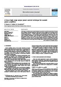
2
1
1
Fig. 1. Four-antenna MRA, virtual six-antenna ULA, and the corresponding difference coarray. Na > N [2], [3]. The uniform linear array with virtual antennas, which is co-array equivalent to the physical array, is capable of suppressing Na − 1 jammers, which is higher than the number N of physical sensors. In order to briefly explain the concept of the proposed scheme, we consider as an example the four-antenna minimum redundancy array (MRA), shown in the upper plot of Fig. 1. The corresponding covariance matrix R x has the following structure, r(1) r(4) r(6) r(0) r(−1) r(0) r(3) r(5) , (3) R x = r(−4) r(−3) r(0) r(2) r(−6) r(−5) r(−2) r(0) where r(i) is the correlation between the received signals at two sensors with an inter-element spacing of i times one-half wavelength, i.e. r(i) = E{x(l)x∗ (l − i)}. Using the entries of the covariance matrix R x corresponding to the unique nonnegative spatial lags i = 0, · · · , 6, we obtain the augmented covariance matrix Ra of a co-array equivalent virtual sixantenna uniform linear array, shown in the middle plot of Fig. 1, as r(0) r(1) r(2) r(3) r(4) r(5) r(6) r∗ (1) r(0) r(1) r(2) r(3) r(4) r(5) ∗ r (2) r∗ (1) r(0) r(1) r(2) r(3) r(4) ∗ Ra = r (3) r∗ (2) r∗ (1) r(0) r(1) r(2) r(3) , ∗ ∗ ∗ ∗ r(1) r(2) r∗ (4) r∗ (3) r∗ (2) r∗ (1) r(0) r (5) r (4) r (3) r (2) r∗ (1) r(0) r(1) ∗ r (6) r∗ (5) r∗ (4) r∗ (3) r∗ (2) r∗ (1) r(0) It is noted that negative spatial lags are redundant due to their conjugate relationship with positive lags. Since every entry of Ra can be obtained from R x , the N = 4 element MRA is called a fully augmentable array. Now, the optimum MOP weight vector can be expressed in terms of the augmented covariance matrix Ra as, ˜ w ˜ MOP = µR−1 a f,
(4)
Here, f˜ is a vector of length Na = 7 with its first element being one and others being zero. Since the number of degrees of freedom is increased for the augmented covariance matrix, the maximum number of suppressed jammers is increased from 3 to 6. In essence, for the fully augmentable array, the maximum number of suppressed interferers is limited by the number of the distinct non-redundant spatial lags.
It should be noted that the augmented Toeplitz covariance matrix cannot be guaranteed to be positive semi-definite. Moreover, the increased size of the covariance matrix results in increased variance, on the order of twice the variance for a physical uniform linear array [5]. In order to compensate for the performance degradation, the number of samples in estimating the data covariance matrix should be sufficiently large. Since the strong jamming signals are dominant in the GPS scenario, the eigen-analysis based MOP algorithm can be utilized to mitigate the effects of covariance augmentation [6]. The eigen-decomposition of the augmented covariance matrix Ra is given by Ra =
K X
λk uk ukH +
Na X
λk uk ukH ,
(5)
k=K+1
k=1
The subspace of K strongest interferers is approximated by the K eigenvectors and Na is the number of distinct spatial lags. The estimate of the interference subspace with additive white noise is given by ˜a = R
K X
λk uk ukH + σI,
(6)
k=1
Here, σ provides robustness to steering vector errors as a regularization term. Then, the inverse of the interference subspace with noise is given by, K X λk −1 −1 H ˜ Ra = σ I − uk uk , (7) λ +σ k=1 k Thus, the optimum MOP weight vector can be expressed as ˜ a−1 f˜, w ˜ MOP = µR
(8)
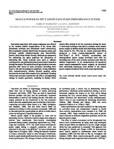
For simulation, we use the four-antenna MRA, shown in Fig. 1. Assume there are six jammers with interference to noise ratio being 20 dB. We implement both MOP algorithms in Eq. (4) and Eq. (8) to null the jamming signals. The obtained beampatterns of both MOP weight vectors are shown in Fig. 2. We can see that both methods can null the 6 jammers, with the eigen-analysis based MOP method exhibiting deeper nulls. II. REFERENCES [1] M. G. Amin and W. Sun, “A novel interference suppression scheme for global navigation satellite systems using antenna array,” Selected Areas in Communications, IEEE Journal on, vol. 23, no. 5, pp. 999–1012, 2005. [2] Y. Abramovich, N. Spencer, and A. Gorokhov, “Detection-estimation of more uncorrelated gaussian sources than sensors in nonuniform linear antenna arrays .i. fully augmentable arrays,” Signal Processing, IEEE Transactions on, vol. 49, pp. 959–971, May 2001. [3] S. Pillai, Y. Bar-Ness, and F. Haber, “A new approach to array geometry for improved spatial spectrum estimation,” Proceedings of the IEEE, vol. 73, pp. 1522–1524, Oct 1985.
0
MOP beampattern:dB
−10
−20
−30
−40
MOP jammer eigen−MOP
−50
−60 0
20
40
60
80 100 120 azimuth angel:deg
140
160
180
Fig. 2. MOP beampattern based on covariance augmentation.
[4] A. Moffet, “Minimum-redundancy linear arrays,” Antennas and Propagation, IEEE Transactions on, vol. 16, no. 2, pp. 172–175, 1968. [5] S. Pillai and F. Haber, “Statistical analysis of a high resolution spatial spectrum estimator utilizing an augmented covariance matrix,” Acoustics, Speech and Signal Processing, IEEE Transactions on, vol. 35, pp. 1517–1523, Nov 1987. [6] J. L. Odom and J. L. Krolik, “Adaptive beamforming with augmentable arrays in non-stationary environments,” in Computational Advances in Multi-Sensor Adaptive Processing (CAMSAP), 2013 IEEE 5th International Workshop on, pp. 324–327, IEEE, 2013.