Proceedings of the International Multiconference on Computer Science and Information Technology pp. 649–656
ISBN 978-83-60810-14-9 ISSN 1896-7094
Minos—The design and implementation of an embedded real-time operating system with a perspective of fault tolerance Thomas Kaegi-Trachsel
Juerg Gutknecht
Native Systems Group ETH Zurich 8092 Zurich, Switzerland Email:
[email protected]
Native Systems Group ETH Zurich 8092 Zurich, Switzerland Email:
[email protected]
Abstract—This paper describes the design and implementation of a small real time operating system (OS) called Minos and its application in an onboard active safety project for General Aviation. The focus of the operating system is predictability, stability, safety and simplicity. We introduce fault tolerance aspects in software by the concept of a very fast reboot procedure and by an error correcting flight data memory (FDM). In addition, fault tolerance is supported by custom designed hardware.
I. I NTRODUCTION
W
E DEVELOPED Minos in the context of a European Union Research project called Onbass [1]. The following quote of the Onbass homepage gives an overview of the project goals: The final goal of the project is to design, develop, test and validate an on-board active real-time data processing system that will monitor flight related parameters and react in the case of a proliferation of risk to the aircraft or its occupants. The system will recognise undesirable trends or patterns in data relating to the various aircraft agents (aircraft, systems, pilot) by analyzing and comparing current flight data against previously accumulated aircraft-specific behavioral data. As a result, timely interventions could be made in order to eliminate the associated risk(s) or to minimise the severity of the corresponding effects. In addition, the system will offer invaluable and comprehensive data for post-flight analysis upon which aviation safety bodies could base and/or redesign safety policies and procedures. The interested reader may refer to [2]–[4] for further information about the application side of the Onbass project, the theory of Active Safety and its implementation. In this paper we shall describe the operating system developed during the project, with an emphasis on two fault tolerance aspects: a.) recovering from memory faults mainly caused by radiation and b.) reliably recording flight data in a Flight Data Memory (FDM). A FDM is a reliable persistent storage system for flight data such as heading, temperature, engine information, etc. recorded in real time during the flight.
The main concept used to increase dependability [5] in our project is managed redundancy. Duplication of the main memory (see chapter II) and of the flight data memory (see chapter VI) lead to a substantially higher level of reliability. II. T HE H ARDWARE P LATFORM The hardware platform was custom designed and built for this project by IRoC Technology in Grenoble, France, according to the requirements given by the Onbass project specification. The FPGA implementation [6] features a CPU, synthesised from a standard (non fault tolerant) ARM7TDMI IP core by Actel, a fault tolerant main memory (RAM) and a fault tolerant ROM. Fault tolerant RAM and ROM provide safeguards against both temporary and permanent errors. Temporary errors, for example bit flips, are mainly induced by radiation such as alpha particles, neutrons or heavy ions that are generated by solar winds or by other cosmic radiation. At sea level, these events happen rarely because most of the radiation is filtered by the earths atmosphere. However, at typical flight altitude (10km above sea level) or in deep space several hundred or thousand kilometers above ground, experiments have shown [7] that such events occur as frequently as 5.55 times per megabyte RAM per day in average. ROM is much less susceptible to such events, but they can still occur. Permanent errors on the other hand affect both, RAM and ROM equally. Such errors usually manifest themselves as failures of parts of or the entire physical memory chip. In the former case, only certain regions are affected, in the latter case the whole chip fails. If a temporary fault occurs, the system should recover as quickly as possible and continue its operation from the most recent consistent state. In the case of a permanent error, the system is supposed to still continue its operation, possibly in a degraded mode, after signalling the failure to the runtime and application. The following sections describe the strategies chosen for dealing with the two types of error just described.
649
650
PROCEEDINGS OF THE IMCSIT. VOLUME 3, 2008
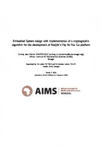
Fig. 1.
ROM Implementation
(Picture courtesy of IRoC Technology)
Memory Subsystem: As a first precaution, static RAM was chosen instead of dynamic RAM as it is faster and more resilient to temporary errors. Physical duplication of memory chips combined with a CRC mechanism provides immunity against a complete failure of any single memory chip. Read/ write operations are always performed simultaneously on two memory chips and, if one of them fails, the error is immediately flagged to the OS. Furthermore, a word-based error detection mechanism was implemented. A 36-bit wide version of SRAM was chosen, where the 4 extra bits per word are used to store a hardwaregenerated Cyclic Redundancy Check (CRC). At each read operation, the data of both memory chips involved is compared against each other. If the comparison fails, the CRC is used to determine the faulty chip, and its partner chip is used to automatically correct the faulty memory location. As these operations are integrated into the memory controller, the comparison can be done without performance penalty, and the correction in case of a mismatch requires just one additional memory access (one CPU cycle). Counters of all corrected and uncorrected errors are provided to the runtime for further analysis or logging. Triplicated memory was considered an alternative to the duplication but an unimproved level of protection regarding temporary faults, longer Mean Time To Failure (MTTF), lower hardware costs and lower heat dissipation favoured the chosen approach. Flash Memory: The binary image of the OS is stored in flash-memory (ROM). The system ROM is physically duplicated but, as it is less susceptible to external influences, no extra bits for error detection are provided. Instead, two instances of the OS image are stored on each ROM chip, one in the first half of the address space and one (in reverse bit order) in the second half, as shown in Figure 1. This procedure can be justified in our case by the extremely small size of the OS image. In order to understand how error detection/ correction in ROM works, we first remember that ROM chips are actually
16 bit wide1 , so that two corresponding 16 bit entities from the two ROM chips fit in one 32 bit word. At boot time, the hardware controller uses this fact for error detection when copying the binary OS image wordwise from ROM into RAM. If the two 16 bit entities in a word do not match, the image stored in the lower ROM part is considered corrupted, and the correct data has to be retrieved from the upper ROM part. As this procedure is only initiated once at boot up, the additional overhead is negligible. Calculations [6] showed that the system just described not only features up to 99% mitigation efficiency regarding to nonpermanent (transient) errors but it also enjoys twice as long Maintainance Free Operating Periods (MFOPs) if compared with a non-redundant implementation. Both, a more extensive reliability analysis and more implementation details, are given in [6]. III. T HE P ROGRAMMING L ANGUAGE O BERON The programming language used in the Onbass project is Oberon 07 [8], [9], a modular descendant of Pascal and Modula-2. Oberon 07 is a simple and safe variant of Oberon [10] for embedded systems. For example, the option of inline assembler code has been removed completely from the language and replaced with a set of safer and more structured custom built-in functions [8]. Oberon07 also provides a mechanism for accelerated calls and execution of ”leaf” procedures that do not contain (further) procedure calls. Parameters and local variables in leaf procedures are allocated in registers (instead of on the stack) whenever possible. The Oberon language is especially suitable for safety critical applications as it is completely type safe and allows no unsafe operations such as type conversions, etc. except in explicitly marked sections for kernel code. IV. T HE A PPLICATIONS Before explaining the design of the Operating System, we would like to give a short overview of the Onbass applications that were supposed to run on the system. This gives an idea about the requirements: Flight Data Acquisition The Onbass system is installed in a general aviation airplane such as a Piper Lance and directly connected to the onboard air data computer that delivers a set of sensor data to the Onbass system up to eight times per second. Black Box Recording After the data acquisition, the raw black box data is stored in the flight data memory (see chapter VI) for later analysis or recovery. Data Parsing Next, the acquired data is parsed and validated according to the air data computer specification. Flight Mode Detection The current flight mode (take off, cruise, etc) is then evaluated. This is especially important, as the valid airplane constraints such as speed, vertical speed, etc. heavily depend on the flight mode. 1 ROM chips use an interlaced addressing scheme, where the first 16 bits in address space belong to the first chip, the second 16 bit belong to the second chip, the third 16 bit to the first chip again, etc.
THOMAS KAEGI-TRACHSEL ET. AL: MINOS—THE DESIGN AND IMPLEMENTATION OF AN EMBEDDED REAL-TIME OPERATING SYSTEM
Airplane safety checks A set of rules is applied to the current airplane flight state to validate the operation of the airplane in terms of safety. In case of detected deviations, a warning is displayed to user via the web interface. Web Server A web server is used to display system information such as configuration options, warnings, etc. via a separate computer to the pilot. Replay For post flight analysis, the system can be configured to load the flight data from the FDM and and use it as data input for the application instead of acquiring the data from the air data computer. Supportive tasks Various other tasks are required to support the system such as additional logging, polling driver tasks for UART and MMC etc. The whole flight data acquisition and analysis must obviously be performed in real time and must be finished before the next flight data set arrives. This imposes requirements on the real time capabilities of the system. V. T HE D ESIGN
OF
M INOS
As a starting point for the runtime system we chose HelyOS [11], an embedded operating system for the control of autonomously operating model helicopters developed at ETH Zurich. We did a substantial rewriting of HelyOS and customised it towards our specific needs as it was too limiting. The resulting system is called Minos and enjoys the following qualities: • Very small, simple and efficient • Suitable for safety critical applications • Predictable in terms of task execution time • Easily portable to other platforms • Highly configurable at boot time • Fast boot up time In the next few chapters we shall give a short introduction to the key concepts of the Minos design. A. Fast Boot Up Special attention was given to system boot up time. A hardware watchdog is used to detect ”stuck” programs caused by a malfunction of either hardware or software. As soon as the watchdog detects a timed-out activity of any kind, the OS and the applications are restarted and brought into the most recent consistent state. This is quite easily possible in this case because all the relevant data has by been stored in the flight data memory by concept IV. In order to achieve a minimum downtime it is important to implement an ultra fast boot up mechanism that, in our case, takes less than 0.5 seconds. Unavoidably this requirement has an impact on various subsystems such as the flight data memory (see chapter VI). B. Memory Management Sytems of the Oberon family [12], [13] traditionally use a completely type-safe ”managed” runtime including garbage collection. However, it is widely known that garbage collection introduces unpredictable latencies in the execution of
651
application programs and garbage collectors for real time systems are complex and difficult to design and implement. As a consequence, other traditional garbage collector based systems, i.e. Java, propose in their real time variants (Real Time Java [14]) the addition of memory outside the scope of the garbage collector for time critical software parts. As explicit memory allocation and deallocation is inherently unsafe and therefore incompatible with safety-critical applications, the only viable option is not to generate garbage at all. We use a closed system approach that still allows applications to allocate dynamic memory but at initialisation time only. An additional benefit of closed systems is that they can never run out of memory. Unavoidably however, there is a price to pay for such simplicity. It is the need for compensatory support for application programming. For example, it is impossible for Minos to permanently keep a dynamic metadata structure for files in memory. Instead, metadata needs to be consistently stored in flash memory, and sector caches are taken from a preallocated buffer pool. As the pool is only used internally by the filesystem and as blocks are automatically recycled when the buffer pool is empty, no ”out of memory” situations can ever occur. C. Interrupt Handling The interrupt handling scheme in Minos is again kept simple. At boot time, the kernel installs a single, general interrupt handler that is responsible for dispatching all signalled interrupts. Device drivers register their own handler in the kernel, where only one handler per interrupt source is currently supported. Interrupt handlers are non interruptable, and their processing time must be kept in limits in order not to compromise realtime guarantees. In the case of multiple interrupts pending, the kernel calls the handlers in the order of ascending interrupt numbers. D. Task Model Original Tasking Scheme: HelyOS uses an ingeniously simple, preemptive tasking scheme that is characterised by the following principles. First, the scheme distinguishes four priorities corresponding to four different task types: Interrupt handlers, high priority periodic tasks running at period s, low priority periodic tasks running at period l = k ∗ s with fixed k, and background tasks. Second, HelyOS uses the following scheduling policy: • Interrupt handlers have highest priority and preempt all other tasks. • High priority periodic tasks preempt low priority tasks and background tasks but no interrupts. • Low priority periodic tasks preempt background tasks but no others. • Background tasks do not preempt any tasks. An interesting consequence of this scheduling policy is the fact that each task must run to completion before any other task of the same priority can start its execution, with the immensely beneficial implication that a single stack is
652
PROCEEDINGS OF THE IMCSIT. VOLUME 3, 2008
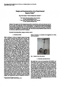
sufficient in principle for implementing the entire scheduling scheme. Modified Tasking Scheme: The scheduling policy just described is not powerful enough for our application. In particular, the restriction to merely two types of periodical tasks corresponding to two fixed periods is too rigid. However, in the interest of avoiding the full complexity of managing multiple stacks and of mastering an intricate synchronisation mechanism, we refrained from switching to a fully general model. Instead, we generalised the HelyOS model appropriately. The most important modification is a new strategy oriented towards ”earliest deadline” scheduling. Both a period and a priority number are preassigned to each task, where the period corresponds to the ”earliest deadline” and the priority number is used to resolve ties. A priority number is also preassigned to background tasks, but of no period of course. Minos Scheduling Principles: • Interrupt handlers have highest priority and preempt all other tasks. • Periodic tasks are scheduled according to their deadline as derived from their period. If two tasks have the same period, the execution order is defined by their priority. • Background tasks are scheduled according to their priority. • Tasks can only be preempted by tasks with a shorter deadline. A consequence of this scheme is the fact that the use of periodic tasks for polling external events is inappropriate, and that interrupts must be used instead. The reason is that a delay in the order of the period (currently 5 ms, but this could be easily changed) is often unacceptable. However, this scheme is still suitable in our case because we are not primarily interested in very fast reaction times but in a predictable behavior in terms of both time and order of execution. If a deadline was missed, then an optional delegate provided by the task object is called. The delegate is responsible for taking recovery actions such as, in the simplest case, merely logging the problem. The next execution of this task is then skipped to give the system time to recover. Note that such a behavior is also necessary to prevent possible stack overflows. Another nice consequence of our simple tasking model is that accessing shared data often needs no synchronisation as the tasks are serialised implicitly. This is notably the case if data structures are shared among tasks of the same period and background tasks only. In the (rarely occurring) other cases where a locking mechanism is required, we use a global system lock that simply disables all interrupts (including timer interrupt). Figure 2 illustrates this tasking scheme. After background task A runs to completion, task B is automatically executed. At this time, neither a periodic task nor an interrupt is pending. At time 50, periodic tasks P and Q are both due, whereas Q has the smaller period and therefore shorter deadline than P. The task B is preempted and Q executed. When Q finishes,
Fig. 2.
Scheduling example
P is automatically invoked because periodic tasks have higher priority than background tasks. At time 63, an interrupt is signaled by the hardware and the respective interrupt handler is called immediately. P is resumed as soon as the interrupt handler has finished its task. When P finishes executing, neither a periodic task nor an interrupt is pending and background task B is resumed. A question naturally arising here is if priority inversion is possible that is if a scenario can be found where some high priority task needs access to a shared resource that is locked by a low priority task so that intervening medium priority tasks can effectively block the execution of the high priority task. In our tasking model, the only synchronisation primitive provided is the global lock. When a task acquires this lock, the task is implicitly set to highest priority (priority ceiling) and the scheduling mechanism is disabled while the lock is held. Because it is impossible that any task holding the global lock is interrupted by another task, priority inversion is impossible. The scheduler itself runs in linear time (linear in the number O(n) of tasks as the due time has to be calculated for each task), and it is thus easy to calculate an upper bound for the scheduler execution time. Our tasking model (see section V-E) pays out in a very efficient task switching algorithm. In fact, the switch from the task scheduler to any other task is synchronous and amounts to just a procedure call (delegate), and the return to the scheduler simply corresponds to the return from the procedure. Only interrupts are asynchronous and therefore require saving of registers on the stack. E. Stack Management The stack management is equally simple. We use a fixed number of separate stacks, one for interrupts, one for periodic tasks and one for background tasks respectively. In principle, one stack would suffice because each task either runs to completion or is preempted by a task of a higher priority, which in turn runs to completion, so that each preempted task finds a clean stack when resumed. However, using a fixed number of separate stacks simplifies the handling of traps. F. Boot Configuration Procedure A particular requirement in our project specification is full configurability of the system at boot time. In the interest of readability, flexibility and ease of configuration, we chose an
THOMAS KAEGI-TRACHSEL ET. AL: MINOS—THE DESIGN AND IMPLEMENTATION OF AN EMBEDDED REAL-TIME OPERATING SYSTEM
XML [15] approach. For each hardware component and each software component, a separate XML section is provided, and a complete set of default settings for all core components is hardcoded into the program and activated at run time before the XML configuration parser is invoked. This serves the purpose of putting the system into a consistent working state even before the configuration file has been read. Due to the restricted policy of allocating dynamic memory, we implemented a considerably simplified SAX [16] based parser that itself does not rely on heap memory. As the system must be able to operate independently of any external host computer, the configuration file can alternatively be stored in flash memory in the device itself or downloaded from a host terminal at boot time. The initialization procedure resulting from all these constraints looks like this: 1) Kernel initialisation, platform setup. 2) Hardware configuration and initialisation by default settings. 3) Mounting of RAM and ROM disc. 4) Acquisition of XML configuration file either by loading it from the ROM disk or by downloading it via a serial connection from a host computer. 5) Processing of the ”autostart” section in the XML file. Can execute any arbitrary command but is especially used to register XML handler plug-ins for the configuration process. 6) The XML parser scans through the rest of the XML file and calls the appropriate plug-ins if one is registered. 7) Enter main command loop. The configuration scheme described above proved to be extremely powerful and flexible. The only negative aspect is the strict top-down parsing order imposed by SAX, which sometimes leads to clumsy configuration clauses. G. Modular System Structure As shown in figure 3, Minos is a fully modular and hierarchically structured system. For the sake of better readability, the (optional) boot configuration mechanism and the XML parser are omitted in the figure. The RAM disk is modelled as a volume object for filesystem containers. Other examples of volume objects are ROM disks and Flash disks. Again in the interest of readability, the dependencies on modules Log and SerialLog are also omitted. SYSTEM This is a pseudo module provided by the Oberon compiler; it provides potentially unsafe functionality required for low level system programming such as memory mapped input/ output. Utmost care must be exercised in code that uses features from module SYSTEM because such code must be considered as potentially unsafe. Platform Platform specific information such as memory layout, interrupt numbers and memory mapped I/O registers. By merely replacing the implementation of this module, Minos can be adapted to a variety of processors of the same architecture, including for example the Marvell PXA255 and the Marvell PXA270.
653
Minos
OFSRamVolumes
Modules
OFS
UART
Log
SerialLog
Device
Strings
FPU
SYSTEM
Fig. 3.
Kernel
MAU
Platform
Core system modules
MAU Memory Allocation Unit, provides the implementation of the memory allocation logic. This module is referenced by the compiler and should not be used directly. FPU Floating Point Emulation. This Module implements runtime support for basic Math operations on floating point numbers as well as for integer division. It is used by the compiler rather than by applications. Strings Basic functionality for copy, search, add, etc. operations on strings. This module is added to the kernel for reuse to avoid code duplication. Kernel The Kernel provides platform-specific tasks such as system initialisation, interrupt handling, timers, etc. It is highly unportable and must be adapted to every platform individually. Device An abstract Character Device used as an abstract interface by plug-in device drivers. It allows the dynamic addition or change of input/ output devices such as (real or virtual) serial ports at runtime. Uart UART device driver, implements a Device.Device plug-in object. Log An abstract logging device that can be used to display log output on different devices such as serial port or Web browser. SerialLog Log over the serial connection. A concrete implementation of module Log. OFS Oberon File System. Provides file operations such as creating, deleting, reading or writing files. It also implements the Oberon File System that is based on the notion of volumes, where a volume is an abstract file system container that provides read/ write access to blocks of fixed size. OFSRamVolumes RAM Disk support. Implements a volume declared as an abstract object in OFS Modules Dynamic module loader. Allows to dynamically download, link and execute modules at runtime. Minos Implements the scheduler and the trap handler and offers user interface commands to be activated via a remote terminal.
654
PROCEEDINGS OF THE IMCSIT. VOLUME 3, 2008
The set of modules presented here is a basic and selfcontained subset of all Minos modules. The modular concept allows software developers to seamlesly add new functionality to the system at any time by simply linking the appropriate modules to the current image. Minos also allows modules to be downloaded, linked and executed dynamically at runtime. This is very convenient for prototyping, testing and debugging. For example, a flexible testing environment can be built by merely flashing to ROM a version of the basic Minos runtime that automatically downloads application code at boot time. The size of the full operating system including all the above listed modules, the XML configuration parser and the boot configuration mechanism is ca. 100 Kbytes. This is less than half the size of a comparable commercial system such as, for example, VxWorks by Wind River (Size of VxWorks 6.2 without XML parser is about 250 Kbytes Basic OS profile [17]). VI. F LIGHT DATA M EMORY A. Introduction An avionics Flight Data Memory (FDM), also called a ”black box”, is an extremely robust and reliable flight data recorder that is typically used in aircrafts for post flight/ post disaster analysis. The current trend in General Avionics goes towards declaring FDM mandatory even in small aircrafts [18]. FDMs often get their input streamed down from an air data computer (ADC) that, in turn, collects the data from a variety of sensors across the airplane. Optionally, FDMs can also be connected to other input sources. Streams of sensor data like heading, height, fuel flow, etc. must be recorded reliably on long life and non-volatile medium such as flash memory or special magnetic tape [18]. Data redundancy schemes such as CRC-32 [19] for error detection, or Reed Solomon for error detection and correction are commonly used to further enhance the reliability of the FDM. Our own choice in Onbass was using CRC-32 for error detection and data duplication on two separate multimedia cards (MMC) for error correction. The FDM in Onbass was designed with the following requirements in mind: • Simple design • Fast data storage and retrieval • Minimum 15 years life time • Fast recovery after unexpected reboot & transparent flight resuming • Transparent MMC device recovery in case of faulty read or write operation • Small memory footprint • Support for replaying stored flights • Human decipherable format • Space efficiency B. MMC vs Compact Flash We had to decide between multimedia cards (MMC) [20] and compact flash cards (CF) [21]. MMC has the advantage of physical compactness and of a low pin count (7 pins),
whereas CF comes with a built in wear-leveling algorithm but has a high pin count (50 pins). We decided in favor of a low pin count because physical connections are arguably the most critical components in any system from a reliability point of view. C. Flash Properties and Limitations Flash memory is organised in blocks (usually 512 bytes) and in erase units consisting of a number of adjacent blocks (usually 32 or 64 [22]. Reads and writes are performed blockwise, and writes must be made only to previously erased blocks. Blocks can either be erased automatically or manually, where the former option is more comfortable while the latter is faster. The number of erases per unit before ”wearing out” is limited, typically to some number between 10000 and 100000. In the interest of longevity of the flash card, the use of a ”wear leveling” strategy is highly advisable. Wear-leveling means that erase cycles and write cycles are evenly distributed across the memory chip. Traditional file systems are unsuitable for flash cards because they exhibit hot spots such as meta data fields that are frequently updated. D. Analysis and Design Considerations In Onbass we can take advantage of the fact that the size of records to be stored is fixed (flight data frame plus warnings). As mentioned above, the use of a standard file system is unsuitable as it typically exhibits hot spots. Much of the research [23] into overcoming this problem introduces some virtual-to-physical block number mapping. Two kinds of data structures are typically suggested for this purpose. Direct maps map a logical block number (index i) to its physical sector number. Unfortunately, such data structures have typically a footprint in the order of several megabytes [24]. Inverse maps store in location i the virtual block number corresponding to sector i. These maps are usually stored on the flash disk itself and are mainly used for regenerating the direct map at boot time. However, after an unexpected reboot, it would take considerable time to rebuild the direct and indirect maps, which is incompatible with the request of a fast reboot time. Also, many of these algorithms are patented. While algorithms based on virtual block mapping can greatly extend the lifetime of flash memory, this comes at the price of increased complexity, of a large memory footprint, and of a garbage collection mechanism for reclaiming invalid sectors. As this is again incompatible with realtime constraints, it is not an option in our case. Another approach is the use of a log structured file system such as JFFS [25]. Log structured file systems do not structurally separate metadata and payload data but instead maintain a comprehensive log of all performed operations in chronological order. While wear leveling is implicit in such systems, they still suffer from the garbage collection problem, which again disqualifies them for the use in our project. We should also remember that one of the Onbass requirements (see chapter VI-A) is readability of the data recorded in an FDM without the help of a software decoder. A FDM must
THOMAS KAEGI-TRACHSEL ET. AL: MINOS—THE DESIGN AND IMPLEMENTATION OF AN EMBEDDED REAL-TIME OPERATING SYSTEM
655
buffer. In the latter case, the FDM software deletes the oldest flight and continues recording. F. Module View
Fig. 4.
FDM Implementation Overview
by law be fully recoverable from scratch. This requirement de facto excludes any sophisticated allocation scheme because recovering data without decoder software would either be impossible at all or at least take considerable efforts. Therefore, we refrained from using such advanced storing schemata and decided in favor of a simple circular buffer structure, where each flight data record occupies the same number of flash card blocks. Whenever a new erase unit is entered, an erase operation is performed as a preparation for subsequent writing. The obvious drawback of this scheme is internal fragmentation if the size of a data element is not an exact multiple of the elementary block size. We considered this as acceptable in particular because more sensor data will have to be stored in the future, which reduces the fragmentation overhead. E. Implementation In addition to the actual flight data, some metadata is recorded on the FDM: The FDM header occupies one erase block and describes the current contents of the FDM. It contains a fingerprint, the number of flights currently stored in the FDM, the flight numbers of the oldest and newest flights currently stored in the FDM, and a list of flight indexes. A flight index in turn points to the first and the last header block of the corresponding flight. Flight header blocks again contain a fingerprint (for the support of a scavenging process), the flight number, the starting time of the flight and the date. During flight recording, the pointer to the last block of the current flight index is declared invalid before the flight has properly been closed. This allows the system to detect unexpected reboots and, as each flight data block is stamped with the corresponding flight number, to use a binary search procedure for locating the most recently recorded flight data block. Prior to writing, the FDM software must check whether the next sector is free or the start of the oldest flight in the circular
Figure 4 shows the implementation of the FDM as a layered modular system. Flight Data Memory (FDM) This module provides an API for starting and ending the recording of flight data, for storing and retrieving flight data frames and for performing other administrative tasks. The standard procedure to initialise the flight data memory is registering the FDM module with the XML configuration mechanism by calling the Install procedure and then configuring the flight data memory according to the specification in the XML configuration file. A replay mode (replay of a stored flight) can also be enabled via the configuration file. BBCapture This module is responsible for acquiring the flight data from the application and for periodically storing it. For this purpose, BBCapture installs a periodic task. Serialisation The Serialisation module is responsible for serialising flight data frames into a contiguous data stream to be fed to the FDM. BBReplication This layer partly implements the error detection/correction algorithms. In detail, the module is responsible for computing the CRC-32 for each block. The CRC32 is automatically generated during write operations and automatically checked during read operations. All read/ write operations are performed sequentially on two configurable partitions on two distinct flash cards. At each read operation, data integrity is checked automatically. If a faulty CRC-32 is detected, the healthy copy is used to fix the data by merely rewriting the faulty block and an error indication is returned. If one of the flash cards fails permanently, the system still continues to record data on the healthy card, and a log message plus an appropriate status code are generated to indicate the failure. BBVolumes Flash disks usually come with a standard partition table and thereby support the coexistence of an FDM and standard file systems on the same disk. BBVolumes implements a disk volume object that represents a logical volume, in our case a partition, and extends its functionality with the ability of erasing erase units on the flash disk. In case of a malfunctioning MMC controller or card, both, the controller and the cards are automatically reset and the failing operation is retried. If it fails again, an error code is returned to indicate the failure. MMC Interface / MMC Driver These two modules implement the multimedia card driver, an interface for reading, writing and erasing blocks and some administrative support such as acquiring cards. VII. C ONCLUSION
AND
F UTURE W ORK
We have built a small and highly reliable realtime operating system that is targeted at safety-critical applications such as the onboard monitoring purpose specified by the Onbass project specification. In numerous real and simulated flight trials (with
656
PROCEEDINGS OF THE IMCSIT. VOLUME 3, 2008
simulated hazards), the system has proved to operate correctly and reliably. However, some scenarios pushed the system to its limits, especially the MMC subsystem. Because recording of flight data is of prime importance in Onbass, it is performed by a periodic real time task. This is possible because writing a disk sector usually takes less than 500 usec. However, in case of any failure, the MMC specification defines a default timeout value of 250 msec [22], which easily goes beyond the time limit of the corresponding periodic task. Our system proved to work reliably even in such cases but only thanks to the low system load. It is advisable to extend the tasking mechanism by an option of suspending a task while waiting for some hardware event. Alternatively, accesses to the MMC controller could be encapsulated in a separate periodically polling task. However, this would lead to a degradation of the sequential read/ write performance as the maximum throughput would be limited by the minimum polling period of the task. The FDM has proved to work reliably as well. Tests performed by intentional modifications of the stored flight data on one or both of the MMC cards showed that all tested inconsistencies (data errors) are reliably detected and (where possible) fixed. A potential improvement in terms of wear leveling could be achieved by periodically moving the FDM header (which is a hot spot) across the medium. Adding spare sectors or entire erase units for a potential replacement of blocks with permanent errors could also improve the lifetime of the system. ACKNOWLEDGMENT The authors would like to thank Felix Friedrich and Florian Negele for their help in designing and implementing the system and for the many hours of intense collaboration and discussions. Many thanks also go to Brian Kirk and to Igor Schagaev for their inspiration and all the contiguous critical and constructive discussions.
R EFERENCES [1] Onbass consortium, “Onbass website,” http://www.onbass.org, 2007. [2] Onbass consortium, “Onbass D1.2 pass functional&reliability-models,” Onbass consortium, Tech. Rep., 2007. [3] I. Schagaev, B. Kirk, and V. Bukov, “Applying the principle of active safety to aviation,” EUCASS 2nd European Conference for Aerospace Sciences, Tech. Rep., 2007. [4] V. Bukov, V. Chernyshov, B. Kirk, and I. Schagaev, “Principle of active system safety for aviation: Challenges, supportive theory, implementation, application and future,” ASTEC’07 ”New challenges in aeronautics”, Tech. Rep., August 19-23, Moscow, 2007. [5] A. Avizienis, J.-C. Laprie, and B. Randell, “Fundamental concepts of computer system dependability,” IARP/IEEE-RAS Workshop on Robot Dependability, Tech. Rep., 2001. [6] D. Alexandrescu, “Onbass deliverable 4.1: Hardware architecture definition,” IRoC Technologies, Tech. Report, 2006. [7] P. P. Shirvani, “Cots technology & issues-space environments,” Center for Reliable Computing, Stanford University, Tech. Rep., 2003. [8] N. Wirth, “Oberon-SA, language and compiler,” ETH Zurich, Tech. Rep., 2007. [9] N. Wirth, “An Oberon Compiler for the ARM Processor,” ETH Zurich, Tech. Rep., 2008. [10] N. Wirth, “Oberon language report,” ETH Zurich, Tech. Rep., 1990. [11] M. Sanvido, “A computer system for model helicopter flight control,” ETH Zurich, Tech. Rep., 1999. [12] N. Wirth and J. Gutknecht, Project Oberon, 2005th ed., 2005. [13] P. J. Muller, “The active object system—design and multiprocessor implementation,” Ph.D. dissertation, ETH Zurich, 2002. [14] G. Bollella, P. Dibble, and et al., “JSR 1: Real-time specification for java,” RTSJ Technical Interpretation Committee, Tech. Rep., 2006. [15] C. M. S.-M. E. M. F. Y. e. a. Time Bray, Jean Paoli, “Extensible markup language (xml) 1.0 (fourth edition),” W3C, Tech. Rep., 2006. [16] W. S. Means and M. A. Bodie, The Book of SAX. No Starch Press, 2002. [17] Wind River Systems, “Wind River General Purpose Platform, VxWorks Edition 3.6,” Wind River Systems, Inc, Tech. Rep., 2007. [18] Onbass consortium, “Onbass D1.1 application domain definition,” Onbass consortium, Tech. Rep., March 2005. [19] M. S. et al., “Reversing CRC—theory and practice,” HU Berlin, Tech. Rep., May 2006. [20] SanDisk, “Multimediacard product manual,” SanDisk, Tech. Rep., 2001. [21] C. F. Association, “CF+ and compact flash specification revision 4.1,” Compact Flash Association, Tech. Rep., 2007. [22] SanDisk, “Host design considerations: NAND MMC and SD-based products,” SanDisk, Tech. Rep., 2002. [23] E. Gal and S. Toledo, “Algorithms and data structures for flash memories,” Tel-Aviv University, Tech. Rep., 2005. [24] L. Chang and T. Kuo, “An efficient management scheme for largescale flashmemory storage systems,” National Taiwan University, Taipei, Taiwan 106, Tech. Rep., 2004. [25] D. Woodhouse, “Jffs : The journalling flash file system,” Red Hat, Inc., Tech. Rep., 2001.