Indian Journal of Geo-Marine Sciences Vol. 40(2), April 2011, pp. 242-249
Design and implementation of embedded multiprocessor architecture for underwater applications Muataz H. Salih & Mohd Rizal Arshad USM Robotics Research Group, School of Electrical and Electronic Engineering, Universiti Sains Malaysia, Engineering Campus, 14300 Nibong Tebal, Seberang Perai Selatan, Pulau Pinang, Malaysia [E-mail:
[email protected],
[email protected]] Received 23 March 2011 revised 28 April 2011 Modern embedded multiprocessors are complex systems that often require years to design and verify. A significant factor is that engineers must allocate a disproportionate share of their effort to ensure that modern FPGA chips architecture behave correctly. This paper proposes a design and implementation of embedded multiprocessors architecture system focusing on its design area and performance. Proposed design presents challenges and opportunities that stem from task coarse granularity and the large number of inputs and outputs for each task. We have therefore designed a new architecture called embedded concurrent computing (ECC), which is implemented on an FPGA chip using VHDL. The performances of a realistic application show scalable speedups comparable to that of the simulation. The results show many data is gathered with the systems, such as size 18699 logic elements and maximum frequency 212 MHz. These data have been gathered by synthesis. Implementation has achieved by the provision of low complexities in terms of FPGA resource usage and frequency. [Keywords: Embedded system design, FPGA system design, multiprocessor, real time processing]
Introduction In recent decades, two forces have driven the increase of the processor performance: Firstly, advances in very-large-scale integration (VLSI) technology and secondly microarchitectural enhancements1. Processor performance has been improved through clock speed increases and the exploitation of instruction-level parallelism. While transistor counts continue to increase, recent attempts to achieve even more significant increase in single-core performance have brought diminishing returns2-3. In response, architects are building chips with multiple energy-efficient processing cores instead of investing the whole transistor count into a single, complex, and power-inefficient core3- 4. Modern embedded systems are designed as systemson-a-chip (SoCs) that incorporate single chip multiple programmable cores ranging from processors to custom designed accelerators. This paradigm allows the reuse of pre-designed cores, simplifying the design of billion-transistor chips, and amortizing costs. In the past few years, parallel-programmable SoCs (PPSoCs) have become a dominant SoC architecture. Several commercial PPSOCs exist today, including the Daytona chip by Bell5-6, the PCx series by picoChip7, and the Viper by Phillips8-9. Successful PPSoCs are high-performance embedded multiprocessors such as the STI Cell10 and the
Sandbridge Sandblaster11. They are dubbed singlechip heterogeneous multiprocessors (SCHMs) because they have a dedicated processor that coordinates the rest of the processing units. A multiprocessor design with SoC like integration of less-efficient, general-purpose processor cores with more efficient special-purpose helper engines is projected to be the next step in computer evolution12. To utilize the raw processing power of these parallel architectures, coarse-grain parallelism in applications should be exploited. Developers should partition applications into coarse-grain units of computation, as well as handle synchronization and communication. Inevitably, these tasks increase the time and cost of application development13-14. The bilevel architecture hierarchical design for PPSoCs, includes support for the extraction of parallelism among coarse-grain units of computations15-16. The goal of our design is two-fold. First, we aim to design the full architecture of an embedded processor for realistic throughput and use it in underwater robotic applications such as in navigational and tracking systems. Second, we aim to achieve this in a complexity-efficient manner; that is, achieve a high operating frequency and consume minimal chip resources.
SALIH & ARSHAD: EMBEODED MULTIPROCESSOR ARCHITECTURE FOR UNDERWATER APPLICATIONS
Materials and Methods Multiprocessor
Multiprocessor system consists of two or more connected processors that are capable of communicating. This can be done on a single chip where the processors are connected typically by either a bus or a NoC. Alternatively, the multiprocessor system can be in more than one chip, typically connected by some type of bus, and each chip can then be a multiprocessor system. A third option is a multiprocessor system working with more than one computer connected by a network, in which each computer can contain more than one chip, and each chip can contain more than one processor. Most modern supercomputers are built this way17. A parallel system is presented with more than one task, known as threads. It is important to spread the workload over the entire processor, keeping the difference in idle time as low as possible. To do this, it is important to coordinate the work and workload between the processors. Here, it is especially crucial to consider whether or not some processors are special-purpose IP cores. To keep a system with N processors effective, it has to work with N or more threads so that each processor constantly has something to do. Furthermore, it is necessary for the processors to be able to communicate with each other, usually via a shared memory, where values that other processors can use are stored. This introduces the new problem of thread safety. When thread safety is violated, two processors (working threads) access the same value at the same time. In the future, we expect thread and process parallelism to become widespread for two reasons: the nature of the applications and the nature of the
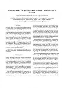
Fig. 1Block diagram of embedded processor
243
operating system. Researchers have therefore proposed two alternative micro architectures that exploit multiple threads of control: simultaneous multithreading (SMT)18-19 and chip multiprocessors (CMP)20-21. Chip multiprocessors (CMPs) use relatively simple single-thread processor cores that exploit only moderate amounts of parallelism within any one thread, while executing multiple threads in parallel across multiple processor cores22. Wide-issue superscalar processors exploit instruction-level parallelism (ILP) by executing multiple instructions from a single program in a single cycle18. Multiprocessors (MP) exploit thread-level parallelism (TLP) by executing different threads in parallel on different processors23. Proposed Design
In this paper, we propose a new multiprocessor architecture called embedded concurrent computing (ECC) using embedded parallel systolic filters (EPSF). Systematic development has enabled the advent of microcontrollers and control units in the form of widespread components. However, they are still dedicated to a given task and the inherently rigid interface. In fact, they have put significant constraints on other application scenarios. This situation has been gradually changing with the introduction of modern CPUs and programmable circuits like FPGA, which have taken a dominant position in computation systems. The universal nature of such electronic components offers a convenient platform for any kind of tasks. The suggested core embedded processor contains a dual-issue, superscalar, pipelined processing unit, along with the other functional elements required to implement embedded SoC solutions. These other functions include memory management and timers. In addition to three separate 128-bit processor local bus (PLB) interfaces, the embedded processor provides interfaces for floating-point functions. This processor includes a two-stage pipeline, consisting of a two-stage, dual-issue task fetch and decode unit with an attached branch unit, and load/store operations, respectively. It also includes a memory management unit (MMU), separate task and data units, and timer facilities. Fig. 1 illustrates the logical organization of the core embedded processor. The task unit of the embedded processor fetches, decodes, and issues two tasks per cycle to any combination of two of the execution pipelines. The task unit includes a branch unit, which provides
244
INDIAN J. MAR. SCI., VOL. 40, NO. 2, APRIL 2011
dynamic branch prediction using a branch history table (BHT), as well as a branch target address cache (BTA). These mechanisms greatly improve the branch prediction accuracy and reduce the latency of the taken branches, such that the target of a branch can usually be immediately executed, without penalty, after the branch itself. The embedded processor contains two execution pipelines: simple integer and load/store. Each pipeline consists of four stages and can access the nine-ports (six read, three write). The simple integer pipeline can handle most arithmetic and logical operations, which do not update the condition register (CR). The load/store pipeline handles all load, store, and memory management. All misaligned operations are handled in the hardware with no penalty on any operation contained within an aligned 16-byte region. The load/store pipeline supports all operations to both big-endian and little-endian data regions. The embedded processor provides separate task and data controllers, which allow concurrent access and minimize pipeline stalls. Both controllers have 32-byte lines and both are 64-way set-associative. Both support parity checking on the tags and data in the memory arrays to protect against soft errors. If a parity error is detected, the processor causes a machine check exception. The task set provides a rich set of memory management tasks for softwareenforced coherency. The implementation also provides a special debug that can directly read the tag and data arrays. The task memory controller connects to the task-side PLB interface of the processor. The data memory controller then connects to the data read and data write PLB interfaces. The MMU provides address translation, access protection, and storage attribute control for embedded applications. It also supports demand paged virtual memory and other management schemes that require the precise control of logical to physical address mapping and flexible memory protection. The translation look-aside buffer (TLB) is the primary hardware resource involved in the control of translation, protection, and storage attributes. It consists of 64 entries, each specifying the various attributes of a given address space page. The TLB is fully associative and the entry for a given page can be placed anywhere in the TLB. The embedded processor contains a time base and two timers: a decrementer (DEC) and a fixed interval
timer (FIT). The time base is a 64-bit counter that is incremented at a frequency either equal to the processor clock rate or as controlled by a separate asynchronous timer clock input to the embedded processor. No interrupt is generated as a result of the time base wrapping back to zero. The DEC is a 32-bit register decremented at the same rate at which the time base is incremented. We load the DEC register with a value to create the desired interval. When the register is decremented to zero, a number of actions occur: the DEC stops decrementing, a status bit is set in the timer status register (TSR), and a decrementer exception is reported to the interrupt mechanism of the embedded processor. Optionally, the DEC can be programmed to automatically reload the value contained in the decrementer auto-reload register (DECAR), after which the DEC resumes decrementing. The timer control register (TCR) contains the interrupt enable for the decrementer interrupt. The FIT generates periodic interrupts based on the transition of a selected bit from the time base. We can select one of the four intervals for the FIT period by setting a control field in the TCR to select the appropriate bit from the time base. When the selected time base bit transitions from 0 to 1, a status bit is set in the TSR and a FIT exception is reported to the interrupt mechanism of the embedded processor. There are three independent 128-bit PLB interfaces in the embedded processor. One PLB interface supports task memory reading, while the other two support data memory reading and writing. All three PLB interfaces are connected as masters to the crossbar in the embedded processor block. The data memory PLB interfaces make requests for 32-byte lines, as well as for 1 to 15 bytes within a 16-byte (quadword) aligned region. The task memory controller makes 32-byte line read requests. Each of the PLB interfaces fully supports the address pipelining capabilities of the PLB, and in fact can go beyond the pipeline depth and minimum latency supported by the PLB. Specifically, each interface supports up to three pipelined request/acknowledge sequences prior to performing the data transfers associated with the first request. For the data memory, if each request is broken into three separate transactions (for example, for a misaligned doubleword request to a 32-bit PLB slave), then the interface actually supports up to nine outstanding request/acknowledge sequences prior to the first data transfer.
SALIH & ARSHAD: EMBEODED MULTIPROCESSOR ARCHITECTURE FOR UNDERWATER APPLICATIONS
The core of our design is focused on a more advanced multiprocessor architecture, especially with regard to the embedded multiprocessor with features such as a core processor containing three concurrent embedded processors, five embedded parallel systolic filters, and a dual port RAM with floating buses, self test sub-system, internal I/O database, view subsystem, control sub-system, and I/O data manager. This design will be suited on a single FPGA chip as shown in Fig. 2. The initial phase of our effort to design a novel multiprocessor architecture with modern features is closely tied to a simple and parallel processing method. This architecture is completely designed and implemented towards embedded concurrent processors. Our processor is a 32-bit device with both data and address buses with a 32-bit width. The entire architecture of our design is illustrated as follows: 1. Embedded multi-processor system-on-chip (EMPSoC): This represents the heart of our design. It is responsible for all computation operations and consists of two main modules. a. Core Processor: The concepts of parallel computing and distributed computing are applied to construct concurrent computing. The core
245
processor consists of three modules: target configuration and optimizer, localizer, and mapping. These modules are independent of processing and work as a single chip processor that involves parallel processing strategy. b. Embedded Parallel Systolic Filters: The synchronous pipeline is composed of different stages, each of which is dedicated to a different stage of processing. Individual stages are separated by embedding additional registers. Pipelined or chained processing may impose different types of conflicts (data and control) which have been addressed in our design by appropriate circuitry structures. To solve this problem, we assign a flag bit for each stage indicating its status. If a flag bit is 0, this means that the stage has finished the process and is ready to accept other data; otherwise, the data from the previous stage will enter into a delay unit of 100 ns each cycle and make the previous stages work on a smaller clock cycle until the flag bit become 0. This part of the embedded processor uses the most familiar filters for data processing in navigation and tracking systems for robots. 2. Floating buses: Previous designs of microprocessors use buses in a specific area of the
Fig. 2The proposed architecture
246
3.
4.
5.
6.
7.
INDIAN J. MAR. SCI., VOL. 40, NO. 2, APRIL 2011
chip. In our design, however, we create a new methodology to build a bus system on a chip. All the buses in the proposed design float, which means that all the modules stand on a sea of buses to make data access very fast and easy for each module on the chip. I/O data manager: The data entered into the FPGA chip come from array of sensors (sound receivers); thus we construct the input unit from a two-dimensional N element matrix that represents the position of each sensor (x and y) and another symmetric matrix for the time of receiving the signal of each sensor. These input signals are collected and reshaped to send to the various modules on the chip, such as databases and EMPSoC. After data are processed from the EMPSoC, it is very important to reshape these data and send them to another module such as the view, control, and output databases. I/O database: In our design, we aim to make a system with higher speed compared to other processors. For this reason, we create an internal database on a chip for input and output data. This avoids access to the external memory, which can cause the system to slow down. Self test sub-system: To check if the system works properly, we design an emulator for the different input signals to represent the different targets and oversee the system behavior. Many parameters are enhanced such as the jitter time, delay time computations, and synchronization signals. View sub-system: Our design focuses on the FPGA chip as a main tool. If we want to display results, we must create a unit that is responsible for translating the processed data to super video graphics array (SVGA) signals and sending it to the decoder (DAC). Control sub-system: Various control signals and motor drivers are generated in this module. Pulse width modulation (PWM) signals for different motor types will generate precisely with very small jitter time.
In this paper, we focus on the design and implementation of a core processor that contains three embedded modules. These modules are built by using new architecture called ECC. The main architecture of each of these modules depends on the suggested architecture maintained above for embedded processors. This new architecture performs computing
and processing via two strategies: (1) Parallel computing and (2) Distributed computing. FPGA Implementation
To aid our design decisions, we devise a design methodology adapted to the specific challenges we are facing. Our methodology for deriving a digital logic implementation of the required functionalities encompasses three steps, each of which comprises a set of choices. The criteria we employ to evaluate the final set of choices are complexity and scalability. We define the complexity of a unit by two metrics: the maximum operating frequency and resource usage. Lower complexity is better; that is, the unit has a higher frequency and consumes less resources. We define scalability as the ability of the unit to expand in a chosen dimension with a minimal increase in complexity. To determine complexity and scalability, we examine the FPGA mapping of the design. In the first step, we start by choosing a particular architectural technique that provides a certain subset of the required functionalities. The second step considers the structural design choices of each architectural technique in terms of the temporal and spatial parallelism necessary to meet throughput and latency requirements. In the third step, we take into consideration the logicimplementation-specific choices driven by the constraints of the target FPGA chip. It is vital to note that the choices in all three steps are interdependent. For instance, an initially appealing architectural technique may require logic design choices that lead toward a prohibitively expensive implementation. In this case, the choice of the architectural technique has to be re-examined. In case there are feasible implementations of the selected architectural technique, the required performance can be achieved by balancing the trade-off between throughputs and operating frequency. Higher throughput necessitates higher design complexity. On the other hand, to achieve high operating frequency, the design complexity should be kept low. The overall performance of the final design is evaluated in terms of the speedup of the benchmarks applications. While this evaluation procedure is straightforward, the performance evaluation of the units in the intermediate phases of the design is more challenging. The performance of a unit can be measured in terms of its throughput and latency. In the early phases of the design, we focus on the design effort and employ temporal and/or spatial parallelism
SALIH & ARSHAD: EMBEODED MULTIPROCESSOR ARCHITECTURE FOR UNDERWATER APPLICATIONS
to meet the performance requirements. However, the required latency and throughput of a particular unit is not available upfront; rather, it has to be inferred from the typical applications. The implementation of the EPSF is performed by the memory components created inside the FPGA chip. The core processor is implemented using our new ECC architecture and our suggested architecture for an embedded processor mentioned in the design section. The core processor takes filtered data from the EPSF module and does a proper action. Our tracking strategy depends on classifying filtered data in patterns to identify underwater subjects. These patterns depend on the signals that come from the array of sound sensors fixed on autonomous underwater vehicles (AUV). This array becomes more sensitive and directive, enabling the system to discriminate between sounds coming from different directions as shown in Fig. 3.
Fig. 3Sensor arrangements on the AUV
In our project, we utilized (32) sound sensors as an array (receivers) on the AUV to cover all directions. The distribution of these sensors on the AUV is as follows: • • • • • •
6 on the right side 6 on the left side 6 in front 6 at the back 6 on top 6 at the bottom
Design Area and Performance
Many data is gathered with the systems, such as size and maximum frequency. These data is gathered by synthesis. When synthesizing, it is possible to optimize with different goal and effort, to get an all uniform and comparable results. Synthesizes have been done with speed as goal and a normal optimization effort, because these gave the best results with the tree structures both concerning speed and area. The synthesize have been made to an Altera Cyclone II FPGA model number EP2C35F672C6. It should also be mentioned that the synthesis tool gives the stated maximum frequencies. Table 1 shows the main used modules and the size of these modules in elements. Fig. 4 shows the graphical representation of the size of these modules. The size of the all design is 18,699 logic elements and the maximum frequency is 212 MHz. It should be noted that the data is acquired by having the component or system as a top-level design. The reason is that this was the only way to get the data from the tools. This means that the Floating buses and controller does not necessarily fill 1022 elements in the system, or that the I/O manager fills 541 elements when used in a system. This only tells the size of the module when used without any other one. Table 1Size of modules Module
Fig. 4Graphical representation of the modules size
247
Kalman Filter Extended Kalman Filter Unscented Kalman Filter Particle Filter Unscented Particle Filter Core processor I/O manager Hardware database Floating buses and controller Self test sub-system View sub-system Control sub-system
No. of elements 1262 1738 1529 1599 1668 6528 541 1162 1022 433 507 711
INDIAN J. MAR. SCI., VOL. 40, NO. 2, APRIL 2011
248
Table 2Speed of signals on both buses From
To
I/P Manager
I/P Address Gen. I/P database Core processor O/P manager O/P database
I/P Manager Kalman filter Core processor O/P manager
Floating buses Normal buses 20.706 ns
72.471 ns
21.615 ns 20.416 ns 21.153 ns 21.112 ns
73.491 ns 71.456 ns 72.618 ns 72.427 ns
With multiple processors a lot of communication will be generated and there is a big possibility that the communication will slow down the system. The floating buses is designed to be better than normal buses. Taking a look at the imaginary case that each module interface send out a data to the same another one at the same time. Due to the nature of floating buses design this would not cause any traffic in the buses, because it is working on paging technique and many copies of buffering system. Table 2 shows some speed of signals on these two kinds of buses along with the flow among modules. According to Table 2, the bus design would be faster than other one, but the clock frequency also has an impact on this. Having a longer bus this problems would occur, unless floating is used. In addition, it has a much higher bandwidth than buses, being able to let many modules communicate with different modules, while only one module can communicate with another one in a bus. To overcome the problems with the bus, it is often pipelined, resulting in using much more area. This extra area is mainly going to buffers, but extra mux’s, and state information is needed. Conclusion The goal of our implementation was two-fold. First, we wanted to design a full architecture of the embedded multiprocessor for realistic performance applications and architecture exploration, and, at the same time, achieve high performance in a complexityefficient manner; that is, to consume minimal chip resources while achieving high operating frequency. Although the embedded multiprocessor was based on well-proven superscalar architectural techniques, including register renaming and parallel execution, these techniques were originally devised for finegrained parallelism among instructions. Therefore, we first analyzed the differences between the coarse-grain architecture and traditional fine-grain superscalar architectural models. Furthermore, we analyzed the impact of these differences on the architectural mechanism, and we identified the modifications
necessary to allow scaling of the architectural mechanisms to coarse-grain computations with large number of arguments. Subsequently, we designed the entire architecture of the embedded multiprocessor. On a high level, it resembles the superscalar pipeline, including the task fetch, decode, rename, and dispatch units. The core contains the task queue, dynamic scheduler, execute unit, and physical register file. The entire unit comprises the back-end of the pipeline. The results presented in this paper show the size of whole design is 18699 logic elements and the maximum frequency is 212 MHz. Acknowledgments The authors would like to thank the Underwater Robotics Research Group (URRG) in the USM for their assistance and NOD, MOSTI, for providing the research grant (Grant no. 6050124). References 1 John L. Hennessy and David A. Patterson. Computer architecture: A quantitative approach. Morgan Kaufmann Publishers Inc., San Francisco, CA, USA, fourth edition 2007. 2 Doug Burger and James R. Goodman. Billion-Transistor Architectures: There and Back Again. IEEE Computer, 37(3):22–28, 2004. 3 David Geer. Industry Trends: Chip Makers Turn to Multicore Processors. Computer, 38(5):11–13, May,2005. 4 AMD Corporation. Multi-core processors: the next revolution in computing White paper, 2005. 5 B. Ackland, A. Anesko, D. Brinthaupt, S.J. Daubert, A. Kalavade, J. Knobloch, E. Micca, M. Moturi, C.J. Nicol, J.H. O’Neill, J. Othmer, E. Sackinger, K.J. Singh, J. Sweet, C.J. Terman, and J. Williams. A Single-chip, 1.6-billion, 16-b MAC/s Multiprocessor DSP. Solid-State Circuits, IEEE Journal of, 35(3):412–424, Mar 2000. 6 Asawaree Kalavade, Joe Othmer, Bryan Ackland, and K. J. Singh. Software environment for a multiprocessor DSP. In DAC ’99: Proceedings of the 36th ACM/IEEE conference on Design automation, pages 827–830, New York, NY, USA, 1999. ACM. 7 picoChip. website. http://www.picochip.com/. 8 S. Dutta, R. Jensen, and A. Rieckmann. Viper: A multiprocessor SOC for advanced set-top box and digital TV systems. Design and Test of Computers, IEEE, 18(5):21-31, Sep-Oct 2001. 9 Martijn J. Rutten, Jos T.J. van Eijndhoven, and Evert-Jan D. Pol. Design of Multitasking Coprocessor Control for Eclipse. Proceedings of the Tenth International Symposium on Hardware/Software Codesign, CODES 2002., pages 139– 144, 2002. 10 H. Peter Hofstee. Power Efficient Processor Architecture and The Cell Processor. In HPCA ’05: Proceedings of the 11th International Symposium on High-Performance Computer Architecture, pages 258–262, Washington, DC, USA, 2005. IEEE Computer Society.
SALIH & ARSHAD: EMBEODED MULTIPROCESSOR ARCHITECTURE FOR UNDERWATER APPLICATIONS
11 Michael Schulte, John Glossner, Sanjay Jinturkar, Mayan Moudgill, Suman Mamidi, and Stamatis Vassiliadis. A LowPower Multithreaded Processor for Software Defined Radio. J. VLSI Signal Process. Syst., 43(2-3):143–159, 2006. 12 Sean M. Pieper, JoAnn M. Paul, and Michael J. Schulte. A New Era of Performance Evaluation. Computer, 40(9):23– 30, 2007. 13 Tarek Abdelrahman, Ahmed Abdelkhalek, Utku Aydonat, Davor Capalija, David Han, Ivan Matosevic, Kirk Stewart, Faraydon Karim, and Alain Mellan. The MLCA: A Solution Paradigm for Parallel Programmable SOCs. In IEEE NorthEast Workshop on Circuits and Systems (NEWCAS), pp. 253-253, June, 2006. 14 Farayadon Karim, Alain Mellan, Anh Nguyen, Utku Aydonat, and Tarek S. Abdelrahman. A Multi-Level Computing Architecture for Embedded Multimedia Applications. IEEE Micro, 24(3):55–56, 2004. 15 Utku Aydonat and Tarek S. Abdelrahman. Parallelization of Multimedia Applications on the Multi-Level Computing Architecture. In Parallel and Distributed Computing and Systems (PDCS), pages 438–447, 2006. 16 Subbarao Palacharla, Norman P. Jouppi, and James E. Smith. Complexity-Effective Superscalar Processors. In ISCA ’97: Proceedings of the 24th annual international symposium on Computer architecture, pages 206–218, 1997. 17 S. Vazhkudai and X. Ma. Recovering transient data: Automated ondemand data reconstruction and offloading on supercomputers. ACM SIGOPS Operating Systems Review:
18
19
20
21
22
23
249
Special Issue on File and Storage Systems, 41(1):14–18, 2007 D. Tullsen, S. Eggers, and H. Levy, “Simultaneous Multithreading: Maximizing On-Chip Parallelism,” Proc. 22nd Ann. Int’l Symp. Computer Architecture, ACM Press, New York, 1995, pp. 392-403. J. lo, S. Eggers, J. Emer, H. Levy, R. Sstamm, and D. Tullsen. Converting thread level parallelism into instructionlevel parallelism via simultaneous multithreading. ACM Transactions on Computer Systems, 15(2), pp. 323-354, August 1997. Olukotun, K., Nayfeh, B. A., Hammond, L., Wilson, K., and Chang, K. 1996. The case for a single-chip multiprocessor. In the 7th International Conference on Architectural Support for Programming Languages and Operating Systems (ASPLOS-7), Cambridge, MA, ... Cambridge, MA, September, pp. 2–11. ACM Press, New York, NY. Kyoung Park, Sung-Hoon Choi, Yongwha Chung, Woo-Jong HahnAND Suk-Han Yoon. On-Chip Multiprocessor with Simultaneous Multithreading. http://etrij.etri.re.kr/etrij/ pdfdata/22-04-02.pdf. Lance Hammond, Basem A Nayfeh, Kunle Olukotun. A Single-Chip Multiprocessor. IEEE Computer, vol. 30, no. 9, pp. 79--85, September1997. J. Borkenhagen, R. Eickemeyer, and R. Kalla: A Multithreaded PowerPC Processor for Commercial Servers, IBM Journal of Research and Development, November 2000, Vol. 44, No. 6, pp. 885-98.