28 Jun 2012 ... The write buffer in Spansion® MirrorBit® Flash memory devices is designed to ...
The page buffer read function accelerates read operations.
AN98479 MirrorBit® Flash Write Buffer Programming and Page Buffer Read AN98479 discusses the specific set of commands to accomplish write buffer programming in Cypress MirrorBit® flash devices.
1
Overview The write buffer in Cypress MirrorBit ® Flash memory devices is designed to reduce the overall system programming time when writing to the device. The host system issues a Write to Buffer command, fills the write buffer with data, and then issues the Programming Buffer to Flash command. The flash device programs the buffered data in parallel, and thus reduces the programming time compared to programming bytes or words one at a time. Depending on the device design, a write buffer can store up to a maximum write buffer size of data that can then be written using a single programming operation. MirrorBit devices use a specific set of commands to accomplish write buffer programming. Refer to the appropriate Cypress data sheet for the complete list of device commands. The page buffer read function accelerates read operations for addresses within a specific range. Table 1 shows Write Buffer size and Page Buffer size for GL-P and GL-S. Table 1. Write Buffer, Page Buffer Size Product
Write Buffer Size
Page Buffer Size
GL-P
32 word / 64 byte
8 word / 16 byte
GL-S
256 word (512 byte)
16 word (32 byte)
Note: 1. Byte mode is not available on the GL-S.
2 2.1
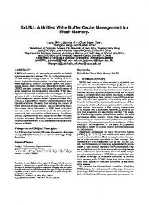
Write Buffer Programming Benefits of Write Buffer Programming The main benefit for the using the write buffer is pure programming speed. Data can be written into the write buffers at the same rate that data can be read from the part (e.g. a 90 ns part can have new data written into the buffer every 90 ns). In the case of the GL-S, data can be written every 60 ns cycle into the buffer even for 90 ns product. The GL-S enables faster programming than the GL-P. The write buffer programs the flash memory array in parallel, greatly decreasing the time needed to write to the Flash. Figure 1 shows that using the write buffers is much more efficient than standard byte or word programming.
www.cypress.com
Document No. 001-98479 Rev. *B
1
MirrorBit® Flash Write Buffer Programming and Page Buffer Read Figure 1, Standard Programming versus Buffer Programming
2.2
Write Buffer Operation Write buffer programming is only available through the Write to Buffer and Program Buffer to Flash command sequences. The Write-to-Buffer Abort Reset command sequence is used to exit out of the Write-Buffer-Abort state. Table 2 lists all software program sequences associated with the write buffer. Table 2. Write Buffer Operation Bus Cycles Command Sequence
Interface
First Addr
Write to Buffer
Word
Second
Data
555
Byte
(Note 2) AAA
Program Buffer to Flash (Confirm)
Word Byte
SA
Write-toBuffer Abort Reset
Word
555
Addr
Third
Fourth
Data
Addr
Data
Addr
55
SA
25
SA
55
XXX
F0
2AA AA
555
Data WC
(Note 1)
Fifth Addr
Data
PA
PD
Sixth Addr WBL
(Note 1)
Data PD
29
(Note 2)
Byte
(Note 2) AAA
2AA AA
555
Legend: PA = Program Address of the memory location to be programmed. This can be any address within the target write buffer page. PD = Program Data to be programmed at location PA. SA = Sector Address containing locations to be programmed. This can be any valid address within the sector.
WC = Write Count is the number of write buffer locations to load minus one (to load 7 locations the WC would be 6). WBL = Write Buffer Location. The address must be within the same write buffer page or Line.
Notes: 1. The sixth cycle must be repeated to complete the number of buffer writes specified by the WC in cycle four. 2. Byte mode is not available on the GL-S.
In Table 2, the host system first loads data at any location in the target write buffer page. Sub-sequent write buffer locations do not need to be loaded in any particular order as long as they reside in the same write buffer page and www.cypress.com
Document No. 001-98479 Rev. *B
2
MirrorBit® Flash Write Buffer Programming and Page Buffer Read sector. In case of GL-S, the write buffer page is defined as the address from xxx0h to xxFFh (any sequence of address where AMAX - A8 do not change). Note that the internal write counter decrements for every data load operation, not for each unique write buffer address location. If the same write buffer location is loaded multiple times, the internal write counter will decrement after each load operation. The last data loaded into a given write-buffer location will be programmed into the device after the Program Buffer to Flash (confirm) command. The host system must therefore account for the effects of loading a write-buffer location more than once. When the Write to Buffer command programming sequence has been completed, the Program Buffer to Flash command (confirm) must be issued to move the data from the write buffer into the flash memory array.
2.3
Write Buffer Programming Abort As stated earlier, write buffer programming cannot be performed across multiple write buffer pages, lines, or across multiple sectors. If this is attempted, the write buffer programming operation will be automatically aborted. The abort condition is detected by performing a status read operation, in which the data shows DQ1 = 1, DQ7 = DATA# (for the “Last Loaded Address”), DQ6 = TOGGLE, DQ5 = 0, and also bit3 in the status register on GL-S. The write buffer programming sequence aborts in the following cases:
Loading a value that is greater than the write buffer size (write-buffer-page) during the “fourth cycle (WC) Numbers of Locations to Program” step.
Writing to an address in a sector that is different than the one specified during the Write-Buffer-Load command.
Writing an Address/Data pair to a different write buffer page than the one selected by the starting address during the “write buffer data loading” stage of the operation.
Writing data other than the Program Buffer to Flash command after loading the specified number of write buffer locations.
Note that the Write-to-Buffer Abort Reset command sequence must be written to the device, after a write buffer program abort, to return the device to READ mode.
2.4
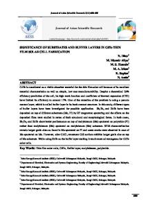
Write Buffer Programming in S29GL-P and S29GL-S Devices In Cypress S29GL-P and S29GL-S devices, write buffer programming with program and erase suspend/resume functionality allows the system to write to a maximum of 32 words (GL-P), 256 words (GL-S) in one programming operation. This provides faster programming performance than word programming. The GL-S can program data at 1.5 MB/s, and includes a status register to check the status of embedded operation. Figure 2 shows write buffer program procedure with ordinary data polling method, and Figure 3 shows the write buffer program with status register. To ensure correct operation, please refer to the appropriate Cypress data sheet for a review of the full write buffer operation.
www.cypress.com
Document No. 001-98479 Rev. *B
3
MirrorBit® Flash Write Buffer Programming and Page Buffer Read Figure 2. Write Buffer Programming Operation with Data Polling Write “Write to Buffer” command Sector Address Write “Word Count” to program - 1 (WC) Sector Address Write Starting Address/Data
Yes WC = 0? Write to a different Sector Address
No ABORT Write to Buffer Operation?
Yes Write to Buffer ABORTED. Must write “Write-to-Buffer ABORT RESET” command sequence to return to READ mode.
No
(Note 4)
Write next Address/Data pair WC = WC - 1 Write Program Buffer to Flash Confirm, Sector Address Read DQ7-DQ0 with Addr = LAST LOADED ADDRESS
Yes DQ7 = Data? No
No No
DQ1 = 1? Yes
DQ5 = 1? Yes
Read DQ7-DQ0 with Addr = LAST LOADED ADDRESS
Yes DQ7 = Data? No FAIL or ABORT (Note 2)
PASS
Notes: 1. DQ7 should be rechecked even if DQ5 = 1 because DQ7 may change simultaneously with DQ5. 2. If this flowchart location was reached because DQ5 = 1, then the device FAILED. If this flowchart location was reached because DQ1 = 1, then the Write Buffer operation was ABORTED. In either case the proper RESET command must be written to the device to return the device to READ mode. Write-Buffer-Programming-Abort-Rest if DQ1 = 1, either Software RESET or Write-Buffer-Programming-AbortReset if DQ5 = 1. 3. See Table
2, . Write Buffer Operation on page 2 for the command sequence as required for Write Buffer Programming.
4. When Sector Address is specified, any address in the selected sector is acceptable. However, when loading Write-Buffer address locations with data, all addresses MUST fall within the selected Write-Buffer Page.
www.cypress.com
Document No. 001-98479 Rev. *B
4
MirrorBit® Flash Write Buffer Programming and Page Buffer Read Figure 3. Write Buffer Programming Operation with Status Register Write “Write to Buffer” command Sector Address Write “Word Count” to program - 1 (WC) Sector Address Write Starting Address/Data
Yes WC = 0? Write to a different Sector Address
No Abort Write to Buffer Operation?
Yes Write to Buffer Aborted. Must write “Write-to-Buffer Abort Reset” command sequence to return to Read mode.
No
(Note 2)
Write next Address/Data pair WC = WC - 1 Write Program Buffer to Flash Confirm, Sector Address Read Status Register
DRB SR[7] = 0?
Yes
No PSB SR[4] = 0?
Yes
No Program Fail
Yes
Program Successful
WBASB SR[3] = 1? No SLSB SR[1] = 0?
Yes
No Program aborted during Write to Buffer command
Sector Locked Error
Program Fail
Notes: 1. See Table 6.1, Command Definitions in GL-S data sheet for the command sequence as required for Write Buffer Programming. 2. When Sector Address is specified, any address in the selected sector is acceptable. However, when loading Write-Buffer address locations with data, all addresses MUST fall within the selected Write-Buffer Page.
www.cypress.com
Document No. 001-98479 Rev. *B
5
MirrorBit® Flash Write Buffer Programming and Page Buffer Read
3 3.1
Page Buffer Reads Page Buffer Read Introduction Whenever the host system changes a “page address” (or toggles CE# during a read), the device performs a “random access”. During this “random access” the read page buffer is loaded in parallel with data within the selected read-page boundaries. Subsequent intra-page accesses are 3 to 8 times faster than random accesses because the data are already available in the buffer. Therefore, read performance is significantly improved. Figure 4. Page Buffer Read Timing Diagram
GL-S: Amax-A4 GL-P: Amax-A3 GL-S: A3-A0 GL-P: A2-A0 (Note)
Data Bus
Same Page
Aa tACC
Ab tPACC
Qa
Ad
Ac tPACC
Qb
tPACC
Qc
Qd
CE# OE# Note: The timing diagram shows device in word mode. Addresses A2–A-1 are used during byte mode on the GL-P.
3.2
Read Buffer Operation with a 8-word / 16-word Page Buffer Cypress page mode flash devices support the use of a multi-word read page buffer. GL-P has an 8-word (16-byte) read page buffer. GL-S has a 16-word (32-byte) read page buffer. For a page buffer read operation, the user must issue a read address, or “RA”, for any memory location. During the initial access time (tCE/tACC) a page of 8words/16-words (16-bytes (GL-P)/32-bytes (GL-S)), starting from a 16-bytes/32-bytes boundary, is read into the page buffer. If the device is in word mode, address bits A3-A0 (GL-S) or A2-A0 (GL-P) can then be used to access any address within the page with a reduced page access time (tPACC). When the GL-P is operated in byte mode, A2 through A-1 are used to access any of the 16-bytes in the read buffer page. The appropriate page is selected by the higher address bits: Amax-A4 (GL-S)/A max-A3 (GL-P) in word mode. Fast page mode accesses are obtained by keeping the high-order “read page address” bits constant and changing the “intra-read page” address bits: A3-A0 (GL-S)/A2-A0 (GL-P) in word mode; A-1 to A2 (GL-P) in byte mode. This is an asynchronous operation with the host system supplying the specific byte or word location.
www.cypress.com
Document No. 001-98479 Rev. *B
6
MirrorBit® Flash Write Buffer Programming and Page Buffer Read A depiction of the command sequence definition for read accesses is shown in Table 3. Table 3. Read Access Bus Cycles Command Sequence
Interface
First
Second
Third
Fourth
Fifth
Addr
Data
Addr
Data
Addr
Data
Addr
Data
Addr
Data
RA
RD
RA
RD
RA
RD
RA
RD
PA
PD
Word Read
Byte (Note 2)
Legend: RA = Read Address
RD = Read Data
Notes: 1. For reading bytes, sixteen or thirty-two consecutive memory locations can be read, compared to eight or sixteen memory locations for reading words. “Intra-read page” locations can be accessed in any order. 2. Byte mode is not available on the GL-S.
A depiction of the device bus operation for read accesses is shown in Table 4. Table 4. Device Bus Operation for Read Access Operation
CE#
OE#
WE#
RESET#
WP#
Address
Data
Read
L
L
H
H
X
AIN
DOUT
During page buffer read operations, the CE# pin must be kept at voltage level V IL during all fast page mode accesses. If the CE# pin toggles or changes state during a page buffer read operation, the current data transfer will automatically be aborted and another initial page access is started. This will result in an unnecessary delay in read timings.
4
Conclusion The write buffer programming feature of MirrorBit flash memory devices can decrease the programming time by over 20%, when compared to single word programming. Furthermore, the GL-S can eliminate programming time over 90% due to its new enhanced architecture called MirrorBit Eclipse™ Flash memory. Write buffer programming is enabled via a simple addition of three commands to the standard embedded algorithm bus command set. The read page buffer feature of MirrorBit flash memories can increase performance significantly. Following each random (inter-page) access, all locations of the referenced 8-word (GL-P) or 16-word (GL-S) page are available for fast access. When multiple read accesses are grouped within a page the average read performance can be increased by 3 to 8 times.
www.cypress.com
Document No. 001-98479 Rev. *B
7
MirrorBit® Flash Write Buffer Programming and Page Buffer Read
Document History Page Document Title: AN98479 - MirrorBit® Flash Write Buffer Programming and Page Buffer Read Document Number: 001-98479 Rev.
ECN No.
Orig. of Change
Submission Date
Description of Change
**
–
–
06/28/2012
*A
4955476
MSWI
10/09/2015
Updated in Cypress template
*B
5821101
AESATMP8
07/17/2017
Updated logo and Copyright.
www.cypress.com
Initial version
Document No. 001-98479 Rev. *B
8
MirrorBit® Flash Write Buffer Programming and Page Buffer Read
Worldwide Sales and Design Support Cypress maintains a worldwide network of offices, solution centers, manufacturer’s representatives, and distributors. To find the office closest to you, visit us at Cypress Locations.
PSoC® Solutions
Products ARM® Cortex® Microcontrollers
cypress.com/arm
PSoC 1 | PSoC 3 | PSoC 4 | PSoC 5LP | PSoC 6
Automotive
cypress.com/automotive
Cypress Developer Community
Clocks & Buffers
cypress.com/clocks
Interface
cypress.com/interface
Forums | WICED IOT Forums | Projects | Video | Blogs | Training | Components
Internet of Things
cypress.com/iot
Technical Support
Memory
cypress.com/memory
cypress.com/support
Microcontrollers
cypress.com/mcu
PSoC
cypress.com/psoc
Power Management ICs
cypress.com/pmic
Touch Sensing
cypress.com/touch
USB Controllers
cypress.com/usb
Wireless Connectivity
cypress.com/wireless
All other trademarks or registered trademarks referenced herein are the property of their respective owners.
Cypress Semiconductor 198 Champion Court San Jose, CA 95134-1709
© Cypress Semiconductor Corporation, 2012-2017. This document is the property of Cypress Semiconductor Corporation and its subsidiaries, including Spansion LLC (“Cypress”). This document, including any software or firmware included or referenced in this document (“Software”), is owned by Cypress under the intellectual property laws and treaties of the United States and other countries worldwide. Cypress reserves all rights under such laws and treaties and does not, except as specifically stated in this paragraph, grant any license under its patents, copyrights, trademarks, or other intellectual property rights. If the Software is not accompanied by a license agreement and you do not otherwise have a written agreement with Cypress governing the use of the Software, then Cypress hereby grants you a personal, non-exclusive, nontransferable license (without the right to sublicense) (1s) under its copyright rights in the Software (a) for Software provided in source code form, to modify and reproduce the Software solely for use with Cypress hardware products, only internally within your organization, and (b) to distribute the Software in binary code form externally to end users (either directly or indirectly through resellers and distributors), solely for use on Cypress hardware product units, and (2) under those claims of Cypress's patents that are infringed by the Software (as provided by Cypress, unmodified) to make, use, distribute, and import the Software solely for use with Cypress hardware products. Any other use, reproduction, modification, translation, or compilation of the Software is prohibited. TO THE EXTENT PERMITTED BY APPLICABLE LAW, CYPRESS MAKES NO WARRANTY OF ANY KIND, EXPRESS OR IMPLIED, WITH REGARD TO THIS DOCUMENT OR ANY SOFTWARE OR ACCOMPANYING HARDWARE, INCLUDING, BUT NOT LIMITED TO, THE IMPLIED WARRANTIES OF MERCHANTABILITY AND FITNESS FOR A PARTICULAR PURPOSE. To the extent permitted by applicable law, Cypress reserves the right to make changes to this document without further notice. Cypress does not assume any liability arising out of the application or use of any product or circuit described in this document. Any information provided in this document, including any sample design information or programming code, is provided only for reference purposes. It is the responsibility of the user of this document to properly design, program, and test the functionality and safety of any application made of this information and any resulting product. Cypress products are not designed, intended, or authorized for use as critical components in systems designed or intended for the operation of weapons, weapons systems, nuclear installations, life-support devices or systems, other medical devices or systems (including resuscitation equipment and surgical implants), pollution control or hazardous substances management, or other uses where the failure of the device or system could cause personal injury, death, or property damage (“Unintended Uses”). A critical component is any component of a device or system whose failure to perform can be reasonably expected to cause the failure of the device or system, or to affect its safety or effectiveness. Cypress is not liable, in whole or in part, and you shall and hereby do release Cypress from any claim, damage, or other liability arising from or related to all Unintended Uses of Cypress products. You shall indemnify and hold Cypress harmless from and against all claims, costs, damages, and other liabilities, including claims for personal injury or death, arising from or related to any Unintended Uses of Cypress products. Cypress, the Cypress logo, Spansion, the Spansion logo, and combinations thereof, WICED, PSoC, CapSense, EZ-USB, F-RAM, and Traveo are trademarks or registered trademarks of Cypress in the United States and other countries. For a more complete list of Cypress trademarks, visit cypress.com. Other names and brands may be claimed as property of their respective owners.
www.cypress.com
Document No. 001-98479 Rev. *B
9