Olutola Jonah, Stavros V. Georgakopoulos, Daerhan Daerhan and Shun Yao. Department of Electrical Engineering,. Florida International University, Miami, ...
Misalignment-Insensitive Wireless Power Transfer Via Strongly Coupled Magnetic Resonance Principles Olutola Jonah, Stavros V. Georgakopoulos, Daerhan Daerhan and Shun Yao Department of Electrical Engineering, Florida International University, Miami, FL 33174 Abstract— An efficient wireless power transfer (WPT) of strongly coupled magnetic resonance (SCMR) with loops is shown here. This paper shows an optimal 3D loop design for SCMR systems, that is insensitive to misalignment, and exhibits higher efficiency than typical SCMR devices.
I.
INTRODUCTION
Wireless power transfer methods have been proposed and studied for various applications. some WPT system used nearfield coupling in several applications such as, RFID tags, telemetry and implanted medical devices [1]. In addition, other WPT methods have been reported to exhibit high efficiencies (order of 90%) for short distances (1-3 cm). However, the efficiency drops drastically [2]. This paper focuses on the design of WPT based on the SCMR method. II.
OPTIMAL SCMR DEVICES
It is important to ensure that the SCMR devices are optimal prior to misalignment analysis. Hence, the optimized geometrical parameters previously derived in [2] for loops and helices (maximum Q-factor, frequency of the maximum Qfactor and maximum efficiency) are used in the analysis. The specific conditions and equations for optimal parameters will be extended for application in other geometries in Fig. 1 and in Fig. 2. The parameters, the maximum Q-factor and the frequency of the maximum Q-factor of the each loop in a typical SCMR is as derived in [2] from: ⎡ ⎛ 8r ⎞ ⎤ L = μ o r ⎢ ln ⎜ ⎟ − 2⎥ ⎣ ⎝ rc ⎠ ⎦
R rad = (π / 6 )η o ( 2π f r r / c )
Rohm =
(
(1) 4
(2)
)
⎛ μ0 ρπ r f max ⎜⎜ rc2 ⎝ 2
L( Ortholoops ) =
⎡ ⎛ 8r = μ o r ⎢ ln ⎜ ⎣ ⎝ rc
⎤ ⎞ ⎟ − 2⎥ ⎠ ⎦
(6)
1 4 (7) Rrad = (π / 6 )η o ( 2π f r r / c ) 2 1 (8) Rohm ( ortholoops ) = Rohm s = μ o ρπ f r Nr / rc 2 The frequency of the maximum Q-factor and maximum Qfactor are: c 8 / 7 μ 1/ 7 ρ 1/ 7 (9) f max ( Orth oloops ) ( r , rc ) = 4 ⋅ 15 2 / 7 rc 2 / 7 π 11/ 7 r 6 / 7
(
Q max( Ortholoop ) =
)
(10)
2π f max μ 0 r ln(8 r / rc − 2) ⎛ μ 0 ρπ r 2 f max ⎜⎜ rc2 ⎝
1 2
⎞ 2π f max r ⎞ 2 ⎛ ⎟⎟ + 20π ⎜ ⎟ c ⎝ ⎠ ⎠
4
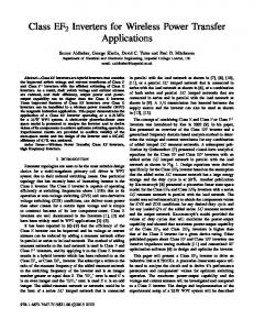
In the second scenario, the two orthogonal loops of Fig. 1 are unified into a single 3D loop shown in Fig. 2. In this case, geometrically the loops are orthogonal (See Fig. 2a), but in the equivalent circuit (See Fig. 1b), the two loops are connected in series and the geometrical parameters can be written as: ⎡ ⎛ 8r ⎞ ⎤ L(3 Dloops ) = 2 L = 4 μ o r ⎢ ln ⎜ ⎟ − 2 ⎥ ⎣ ⎝ rc ⎠ ⎦
R rad ( 3 Dloops ) = 2 R rad
4
⎞ 2π f max r ⎞ 2⎛ ⎟⎟ + 20π ⎜ ⎟ ⎝ c ⎠ ⎠
978-1-4799-3540-6/14/$31.00 ©2014 IEEE
1 L 2
R rad ( Ortholoops ) =
(5)
2π f max μ0r ln(8r / rc − 2) 1 2
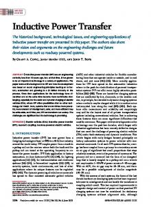
(a) (b) Fig. 1. Two orthogonal loops (disconnected but form 3D structure) (a) two orthogonal loops model geometry, (b) the equivalent circuit. In Fig. 1, even though geometrically the loops are orthogonal (See Fig. 1a), but are connected in setup and analysis, hence, in the equivalent circuit (See Fig. 1b), the two loops are connected in parallel, the geometrical parameters can be written as:
(3)
μ o ρπ f r r / rc
where μ is the permeability of free space, ρ is the loop's material resistivity, r is the radius of the loop, rc is the cross sectional wire radius, f is the frequency, ηo is the impedance of free space and c is the speed of light. It should also be noted that (1)−(3) are valid only when r < λ /6π [2]. The equations for optimal Q-factor, Qmax, and the frequency, fmax, are [2]: c 8 / 7 μ 1/ 7 ρ 1/7 (4) f max ( r , rc ) = 4 ⋅ 15 2 /7 rc 2 /7 π 11/ 7 r 6 / 7 Qmax (r, rc ) =
The geometry and equivalent circuit the two orthogonal loops (loops disconnected but form 3D structure) is as follows:
= 4 ( π / 6 )η o ( 2 π f r r / c )
Rohm (3 Dloops ) = 2 Rohms = 4
1343
(
)
μ o ρπ f r r / rc
(11) 4
(12) (13)
AP-S 2014
70 Simulation Measurement
60
Efficiency (%)
50 40 30 20
(a) (b) Fig. 2. Two orthogonal loops (Unified and form 3D structure) (a) two orthogonal loops model geometry, (b) the equivalent circuit. The frequency of the maximum Q-factor and maximum Qfactor are: c 8 / 7 μ 1/ 7 ρ 1/ 7 (14) f max ( 3 Dloop ) ( r , rc ) = 4 ⋅ 15 2 / 7 rc 2 / 7 π 11/ 7 r 6 / 7 Q max (3 Dloop ) =
1
⎞2 2π f max r ⎞ 2 ⎛ ⎟⎟ + 20π ⎜ ⎟ c ⎝ ⎠ ⎠
0 0
20
30
40 50 Angle(°)
60
70
80
90
(a) Simulation Measurement
70
Efficiency (%)
60 50 40 30 20
4
10 0 0
From (4), (9) and (14) it can be seen that the frequency of the maximum Q-factor, fmax, is the same for three case and hence
20
30
40 50 Angle( °)
60
70
80
90
(b) Simulation Measurement
70 60
(16)
Similarly, from the maximum Q-factor from (5), (10) and (15) it can be seen that the maximum Q-factor, Qmax, is the same for the three scenarios and hence
Qmax ( loop ) = Qmax ( Ortholoop ) = Qmax ( 3 Dloop )
10
80
Efficiency (%)
f max ( loop ) = f max ( Ortholoop ) = f max ( 3 Dloop )
50 40 30 20 10
(17)
A close examination of the optimal parameters of the three scenarios shows that they have identical Qmax and fmax , and the differences in their efficiencies can only be attributed to their different spatial geometrical arrangements. III.
10
80
(15)
2π f max μ 0 r ln(8 r / rc − 2) ⎛ μ 0 ρπ r 2 f max ⎜⎜ rc2 ⎝
10
0 0
10
20
30
40 50 Angle(°)
60
70
80
90
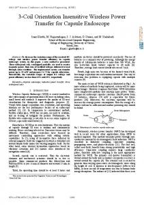
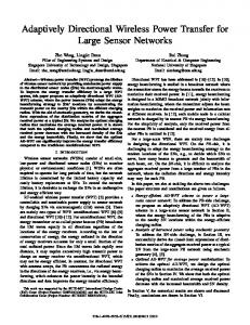
(c) Fig. 4. Efficiencies comparison with angular misalignment. (a) Standard SCMR (b) two orthogonal loops (disconnected), (c) two orthogonal loops (Unified).
SIMULATION AND MEASUREMENT
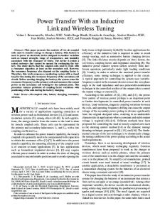
The models were analyzed in ansoft HFSS and laboratory measurement were also carried out (see Fig. 3). The specification of the models are r = 22, rc = 2.2 mm, D = 60 mm, fmax = 195 MHz, Qmax = 920 and the capacitor is 20 pF. The comparison between the measurement and simulation is as shown in Fig. 4. The result showed that Fig. 4(b)) and Fig. 4(c)) are orientation insensitive and more efficient than the standard SCMR shown in Fig. 4(a)), and their efficiencies does not decreases significantly.
CONCLUSION The paper presents optimized SCMR elements with misalignment-insensitive performance. It benchmarked two proposed topologies that features efficiencies above 50% over 0-90 degrees with performance better than typical SCMR with less than 10% in major misalignment topologies. REFERENCES [1]
K. Finkenzeller, RFID Handbook: Fundamentals and Applications in Contactless Smart Cards and Identification, 2nd ed. New York:Wiley, 2003, pp. 65-112.
[2]
O. Jonah, and S. V. Georgakopoulus, "Optimal helices for wireless power transfer via magnetic resonance," Wireless and Microwave Technology Conference (WAMICON), 2012 IEEE 13th Annual , vol., no., pp.1-4, 15-17 April 2012
Fig. 3. A measurement setup of the SCMR experiment
1344