May 20, 2005 - times, which could eventually lead to critical events such as missed times on ... higher levels of automation may result in a situation awareness ...
Mitigation of Human Supervisory Control Wait Times through Automation Strategies by
Paul Jeffrey Mitchell B.S., Queen's University, Kingston, Ontario, Canada, 2002
Submitted to the Department of Aeronautics and Astronautics in partial fulfillment of the requirements for the degree of Master of Science in Aeronautics and Astronautics MASISACHUSETTS INSTUTE OF TECHNOLOGY
at the MASSACHUSETTS INSTITUTE OF TECHNOLOGY May 2005
SJ
IeQ
2 VD
JUN
LIBRARIES
3
(I Massachusetts Institute of Technology 2005. All rights reserved.
. :-.u........................
Author ...............................
Department of Aeronautics and Astronautics May 20, 2005
Certified
by..........
IJ
. " ...... ..
.
"M4y (Missy) L. Cummings
Boeing Assistant Professor of Aeronautics and Astronautics Thesis Supervisor
Acceptedby...............
I~~W
Jaime Peraire Professor of Aeronautics and Astronautics
Chair, Committee on Graduate Students A RCHIVES
fl.-.
2 3 2005
I
Mitigation of Human Supervisory Control Wait Times
through Automation Strategies by Paul Jeffrey Mitchell Submitted to the Department of Aeronautics and Astronautics on May 20, 2005, in partial fulfillment of the
requirements for the degree of Master of Science in Aeronautics and Astronautics
Abstract The application of network centric operations principles to human supervisory control (HSC) domains means that humans are increasingly being asked to manage multiple simultaneous HSC processes. However, increases in the number of available information sources, volume of information and operational tempo, all which place higher cognitive demands on operators, could become constraints limiting the success of network centric processes. In time-pressured scenarios typical of networked command and control scenarios, efficiently allocating attention between a set of dynamic tasks is crucial for mission success. Inefficient attention allocation leads to system wait times, which could eventually lead to critical events such as missed times on targets and degraded overall mission success. One potential solution to mitigating wait times is the introduction of automated decision support in order to relieve operator workload. However, it is not obvious what automated decision support is appropriate, as higher levels of automation may result in a situation awareness decrement and other problems typically associated with excessive automation such as automation bias. To assess the impact of increasing levels of automation on human and system performance in a time-critical HSC multiple task management context, an experiment was run in which an operator simultaneously managed four highly autonomous unmanned aerial vehicles executing an air tasking order, with the overall goal of destroying a pre-determined set of targets within a limited time period. A 4x2(3) repeated measures design was utilized in which the level of decision support provided to operators was a between-subjects factor and level of re-planning, which represents operational tempo, a within-subjects factor. The automated decision support, which took the basic form of a timeline display to aid with scheduling, had four increasing levels: manual, passive, collaborative, and management-by-exception. Level of re-planning refers to how much operators were required to adjust the initial plan in flight, based on unexpected occurrences such as changing deadlines or target sets, and included low and high levels. The passive level of decision support, which provided assistance to the user through color coding and re-organization of scheduling information, was the best overall per3
former as it had no major drawbacks. Management-by-exception had the best performance across several metrics but had a greater number of catastrophic events occur where a UAV erroneously destroyed a friendly target. The manual level performed better than expected, but had a similarly high critical event rate. Contrary to expectations, the collaborative level of decision support, which provided predictions for possible periods of task overload as well as possible courses of action to relieve the high workload, had the worst performance. This is attributable to an unintended consequence of the automation where the graphical visualization of the computer's predictions caused users to try to globally optimize the schedules for all UAVs instead of locally optimizing schedules in the immediate future, resulting in them being overwhelmed. Total system wait time across both experimental factors was dominated by wait time caused by lack of situation awareness, which is difficult to eliminate, implying that there will be a clear upper limit on the number of vehicles that any one person can supervise because of the need to stay cognitively aware of unfolding events. Thesis Supervisor: Mary (Missy) L. Cummings Title: Boeing Assistant Professor of Aeronautics and Astronautics
4
Acknowledgments Thank you to my research advisor, Missy Cummings, for your constant guidance and support. You always believed in me, pushed me to the best of my abilities and allowed
me greater than expected freedom in choosing the path I took with my thesis. With a busy schedule and an always expanding set of graduate students to advise, you have always been responsive to my needs and provided many great ideas along the way. Second, many thanks to my parents for always encouraging me to pursue what I love and to always aim for the very best in whatever I do. Their unwavering support is what convinced me to come to MIT without a guarantee of financial assistance, and has been a solid foundation to lean on while here. Many thanks to all the Humans and Automation Lab graduate students I've worked and interacted with in the past couple of years: Sylvain Bruni, Chris Tsonis, Angela Ho, Jinho Jang, Cristin Smith, and Jessica Marquez. I thank them all for helpful feedback on my interface and experimental designs, as well as for creating
a welcoming and collaborative atmosphere in the lab in which it was a pleasure to work.
I would like to give special thanks to David Moore-Pitman, without whose tireless programming efforts this thesis would never have otherwise been possible. Thanks to Stephane Mercier for his help in refining the performance score detailed in Appen-
dix D. I am also indebted to Tom Sheridan for his always insightful comments and encouragement at every stage of this process. Thanks to everyone else who made my time at MIT fun and exciting, in particular, Kelly Klima, Bill Nadir, Leeland Ekstrom, and Mike Rinehart. Thank you for the fond memories; I leave MIT not just with a Masters degree, but with lifelong friends as well.
5
6
Contents 1 Introduction
19
1.1 Motivation .
1.2
1.1.1
Network Centric Operations . .
1.1.2
Unmanned Aerial Vehicles . . .
1.1.3
Automated Decision Support
Problem Statement.
1.3 Research Objectives . 1.4 Thesis Organization ...........
................. ................. ................. ................. ................. ................. .................
2 Background
19
20 22 24 26 26 26
29
2.1 Overview .
. .
29
2.2 Human Performance.
. .
30
2.3
2.2.1
Appropriate Levels of Automation ..........
. .
30
2.2.2
The Impact of Automation on Human Performance
. .
31
..
34
..
42
..
42
System Performance. 2.3.1
Wait Times.
2.3.2
The Impact of Automation on System Performance
2.3.3
Wait Time Costs.
2.4 Conclusion .
..........................
3 Simulation and Interface Design 3.1
Overview .
45
3.2
Navigation Display.
46 7
3.2.1
Mission Time Window
........
3.2.2
Map Display ............
. . . . . . . . . . . . . . . . . . . . . .
3.2.3
Mission Planning and Execution Bar
. . . . . . . . . . .
50
. . . . . . . . . . .
55
3.3 Decision Support Display ...........
47 48
3.3.1
UAV Status .............
. . . . . . . . . . .
56
3.3.2
Chat Box.
. . . . . . . . . . .
57
3.3.3
UAV Health and Status Updates
. . . . . . . . . . .
59
3.3.4
Decision Support ...........
. . . . . . . . . . .
60
. .
4 Hypotheses and Methods
71
4.1 System Performance Hypotheses .........
. . . . . .
71
4.1.1
Interaction Wait Time (WTI) ......
4.1.2
Wait Time in the Queue (WTQ)
. . .
72
4.1.3
Situation Awareness Wait Time (WTSA) . . .
73
4.1.4
Summary ...............
. . .
74
4.2 Experiment Overview ...............
. . .
74
4.3 Apparatus .....................
. . .
75
4.4 Participants ....................
. . .
76
4.5 Experimental Design ...............
. . .
77
4.5.1
Independent Variables ..........
. . .
77
4.5.2
Dependent Variables ...........
. . .
79
4.5.3
Test Scenario Design ...........
. . .
84
4.5.4
Testing Procedure .............
. . .
86
89
5 Results 5.1
....
71
Overview ............
. .
5.2 Overall Performance Measures . 5.2.1
Performance Score . ..
5.2.2
Time on Target Delays .
.
.
.
.
5.3 Wait Times ........... 5.3.1
Total System Wait Time (WTT) 8
................ ................ ................ ................ ................ ................
89 90 90 90 93
94
5.3.2
Interaction Wait Time (WTI) ........
5.3.3
Wait Time in the Queue (WTQ)
5.3.4
Situation Awareness Wait Time (WTSA)
5.3.5
Wait Time Proportions .
5.3.6
Correlation of Wait Times to Performance
95 96 98 98
5.4
Situation Awareness.
....... .......
5.5
Critical Events.
.......
102
5.6 Workload Measures.
....... ....... ....... .......
104 105 106 107
5.6.1
Subjective Workload.
5.6.2
Secondary Workload.
5.7 Summary 6
......
...... . ...... . ...... . ...... .
.......................
Discussion
109
6.1
Workload.
6.2
Performance.
. . . . . . . . . . . . . . . . . . . .
.....................
109 110
6.2.1
Human Performance.
. . . . . . . . . .
110
6.2.2
System Performance.
. . . . . . . . . .
113
6.2.3
Performance Metrics Conclusion .......
. . . . . . . . . .
115
. . . . . . . . . .
117
. . . . . . . . . .
120
6.3
Situation Awareness.
6.4
Cognitive Saturation and Coping Strategies
....
7 Conclusion 7.1
100 100
i 2:
Overview of Study Motivation .....................
7.2 Significant Findings .
124
7.3 Recommendations and Future Work ..................
126
A MAUVE Rules of Engagement (RoE)
i ti.,
A.1 Naming Conventions.
135
A.2 Arm Payload (Arming) .........................
136
A.3 Fire Payload (Firing) ..........................
136
A.4 Battle Damage Assessment (BDA) ..................
137
9
... .,iiscciaieous s4
.
..............................
137
B Supplemental Experiment Screens
139
C' Descriptive Statistics
141
('. I Demographics
............................
142
142
C.2 Dependent Measures ...........................
D Performance Score D.1
Overview
.
143
. . . . . . . . . . . . . . . .
.
. . . . . . . . ......
D.2 Earned Points ............................... D.3
Penalty
Points . . . . . . . . . . . . . . . .
143 .
. . . . . . ......
E.1
Indicators of Situation Awareness ....................
E.2
Rating
. . . . . . . . . . . . . . .
146
149
E Subjective Situation Awareness (SA) Score
Scales and Scoring
143
149 ......
150
F COUHES Consent Form
153
G Demographic Survey
159
H MAUVE Instructions
163
I Example Trial Time Series
169
10
List of Figures 1-1
Human Supervisory Control [38] .............
1-2
Tenets of NCW [23] ....................
1-3
The Desert Hawk Miniature Unmanned Aerial Vehicle
1-4
The Predator MQ-1 Unmanned Combat Aerial Vehicle
1-5
The Aerosonde Unmanned Aerial Vehicle ........
2-1
The Yerkes-Dodson Law [46] ...............
..... . ..... . ..... . ..... . ..... .
32
2-2 The Relationship Between IT, NT, and WT ...... 3-1
19 21 23 24 25 36
The MAUVE Dual Screen Interface ............. Display
.
.
46
3-2
The MAUVE Navigation, Mission Planning and Execution Display
47
3-3
The Map Display with Legend ................
49
3-4
An Active Target with Mouse-Over Pop Up Window . . .
50
3-5
The Mission Planning and Execution Bar ..........
53
3-6
A Series of Typical UAV Actions at an Active Target . . .
55
3-7
The MAUVE Decision Support Display ...........
3-8
The UAV Status Displays ..................
57
3-9
The Chat Box Window ....................
58
3-10 The UAV Health and Status Updates Window .......
59
3-11 Example High-Level ATO Document ............ 3-12 Example Manual Decision Support Window ........ 3-13 Example Passive Decision Support Window ........ 3-14 Representative Decision Support Visual Timeline ..... 3-15 Example Active Decision Support Window ......... 11
.....
. .. 63
..... . .64 ..... . .65 ..... . .66
3-16 Automation Recommendation for a TOT Delay Request .......
67
3-17 Example Super Active Decision Support Window .......... 3-18 An Arming Exception Box Under Super Active Automation
. .....
68 69
3-19 The 4 Possible Levels of Decision Support in MAUVE .........
69
4-1
74
Predicted Trends for Wait Time Components Across MAUVE LOAs.
4-2 The Experimental Set-Up on the MMWS ................
76
4-3
Test Session Maps .............................
86
5-1
Performance Scores Across Levels of Automation and Re-planning
5-2
TOT Delays Requested Across Levels of Automation and Re-planning
92
5-3
Proportion of Approved TOT Delay Requests Per Level of Automation
93
5-4
WTT Across Levels of Automation and Re-planning ..........
95
5-5
WTI Across Levels of Automation and Re-planning
96
5-6
WTQ Across Levels of Automation and Re-planning
.........
97
5-7
WTSA Across Levels of Automation and Re-planning .........
99
. .
..........
91
5-8 Proportions of WTI, WTQ, and WTSA Per Level of Re-planning . . 100 5-9
Overall SA Scores Across Levels of Automation and Re-planning
5-10 Average Level 2 SA Scores Per Level of Automation
. ..
101
.........
103
5-11 Erroneously Destroyed Targets Per LOA, High Re-planning Session . 104 5-12 Subjective Workload Across Levels of Automation and Re-planning
.
105
5-13 Average Response Times Across Levels of Automation and Re-planning 106
6-1 Comparison of Predicted and Actual WTI Trends ...........
113
6-2 Comparison of Predicted and Actual WTQ Trends ..........
115
6-3 Comparison of Predicted and Actual WTSA Trends ..........
116
6-4 Coping Strategy 1 - Cognitive Shedding .................
121
6-5 Coping Strategy 2 - Degraded Level of Management ..........
122
B-1 The Objectives Screen, Far Left MMWS Monitor
...........
B-2 The Color Coding Table, Bottom Center MMWS Monitor ...... I-1
Super Active and High Re-planning Example - 12:00:59 ........ 12
140
140 170
I-2
Super Active and High Re-planning Example - 12:02:19 ........
171
I-3
Super Active and High Re-planning Example - 12:05:34 ........
172
I-4
Super Active and High Re-planning Example - 12:07:39 ........
173
I-5
Super Active and High Re-planning Example - 12:08:54 ........
174
I-6
Super Active and High Re-planning Example - 12:10:29 ........
175
I-7
Super Active and High Re-planning Example - 12:12:44 ........
176
I-8
Super Active and High Re-planning Example - 12:15:24 ........
177
I-9
Super Active and High Re-planning Example - 12:17:14 ........
178
1-10
Super Active and High Re-planning Example - 12:20:09 ........
179
I-11 Super Active and High Re-planning Example - 12:21:49 ........
180
Super Active and High Re-planning Example - 12:23:04 ........
181
1-12
13
14
List of Tables 2.1
Levels of Automation
3.1
Color Coding of UAV Actions in MAUVE
[39] ........................
31 ...............
46
5.1 Correlation Coefficients between Wait Times and Performance Score . 100 5.2
Summary of Main Effects (p-values) ...................
5.3
Best and Worst Levels of Automation for Dependent Measures ...
108 .
C.1 Descriptive Statistics for Study Demographics ............
108
142
C.2 Descriptive Statistics for all Dependent Measures ..........
.
142
D.1 Base Points Earned For Completion of Primary Mission Objectives D.2 Modified Points Earned for Target Destruction . D.3 Target Difficulty Ratings for the Low Re-planning Scenario ......
146
D.4 Target Difficulty Ratings for the High Re-planning Scenario
147
.....
D.5 Penalty Points for Actions Counter to Mission Objectives ....... E.1 Subjective SA Indicator Rating Scales ..................
15
148 .
16
Nomenclature Abbreviations A
Active (Level of Automation)
ATO
Air Tasking Order
AWC
Air Warfare Coordinator
BDA
Battle Damage Assessment
BDI
Battle Damage Imagery
C2
Command and Control
CE
Command Expression
CSA
Context Switching and Acquisition
DoD
Department
DARPA
Defense Advanced Research Projects Agency
ETA
Estimated Time of Arrival
FO
Fan Out
HSC
Human Supervisory Control
HSCMTM
Human Supervisory Control Multiple Task Managment
IT
Interaction Time
LOA
Level of Automation
LORP
Level of Re-planning
M
Manual (Level of Automation)
MAUVE
Multi-Aerial Unmanned Vehicle Experiment
MICA
Mixed-Initiative Control of Automata
MMWS
Multi-Modal Workstation
NASA
National Aeronautics and Space Adminstration
of Defense
17
NCW
Network Centric Warfare
NCO
Network Centric Operations
NT
Neglect Time
P
Passive (Level of Automation)
PPS
Planning and Problem Solving
'', I,~:
Rules of Engagement . -eserveOfficer Training Corps
RTB
Return to Base
SA
Situation Awareness
9S\
Super Active (Level of Automation)
:1;:.~:\D
Suppression of Enemy Air Defenses
SPAWAR
Space and Naval Warfare
TOT
Time on Target
TLX
Task Load Index
UAV
Unmanned Aerial Vehicle
UCAV
Unmanned Combat Aerial Vehicle
UGV
Unmanned Ground Vehicle
USAF
United States Air Force
UUV
Unmanned Underwater Vehicle
VMS
Vehicle Monitoring and Selection
WT
Wait Time
WTT
Total System Wait Time
WTI
Interaction Wait Time
WTQ
Wait Time in the Queue
WTSA
Situation Awareness Wait Time
18
Chapter 1
Introduction 1.1
Motivation
As modern technology continues to evolve, the role of humans in many systems is shifting from manually controlling a system to that of supervising the system, otherwise known as human supervisory control (HSC). HSC is the process by which a
human operator intermittently interacts with a computer, receivingfeedback from and providing commands to a controlled process or task environment which is connected to that computer. Figure 1-1, adapted from Sheridan [38], illustrates this concept. Human supervisory control is comprised of five generic functions, usually accomplished in the followingcyclical order: planning a computer-based task, teaching the computer what was planned through various inputs, monitoring the computer's actions for errors and/or failures, intervening when the plan has been completed or the computer requires assistance, and then the human learns from the experience [38].
Figure 1-1: Human Supervisory Control [38]
19
As HSC tasks are primarily cognitive in nature and generally do not require constant attention and/or control, it is possible for humans to effectively supervise multiple simultaneous HSC processes.
For example, a single air traffic controller can
handle multiple aircraft because the onboard pilots handle the flying task, while the controller is primarily concerned with navigation and deconfliction tasks that do not require constant attention. In order to maximize human performance for the purposes of cost reduction, efficiency,and safety, there is considerable interest in increasing the number and type of HSC processes a single human can handle. Therefore, it is ever more common for humans to be engaged in multiple HSC task management.
1.1.1
Network Centric Operations
Network Centric Warfare (NCW) is a concept of operations envisioned to increase combat power by effectively linking or networking knowledgeable entities in a bat-
tlespace. Greater combat power is generated through the creation of shared situational awareness, increased speed of command, self-synchronization, and higher operational tempo, lethality and survivability [1]. NCW's basic tenets (Figure 1-2) are as follows [11]: 1. A robustly networked force improves information sharing.
2. Information sharing and collaboration enhance the quality of information and shared situational awareness. 3. Shared situational awareness enables self-synchronization. 4. These, in turn, dramatically increase mission effectiveness.
A force with these capabilities is therefore able to increase combat power by leveraging information superiority. This is a substantial change from the past when traditional methods for boosting combat power were driven by numerical superiority. NCW is a broad concept that is applicable to many different HSC domains other than the military, such as commercial aviation, business ventures, and emergency 20
Figure 1-2: Tenets of NCW [23]
response agencies who are also attempting to leverage intelligent information networks to produce superior performance in time critical settings.
However, the primary
advantage of operations based upon the tenets of NCW (network centric operations or NCO), that of rapid access to information
across the network, will likely be a
major bottleneck and possible point of failure for those humans who must synthesize voluminous data from the network and execute decisions in real-time, often with high-risk consequences under significant uncertainty. Network-centric operations will bring increases in the number of available information sources, volume of information and operational tempo, all which place higher cognitive demands on operators. In time-pressured scenarios like those typical of command and control, efficiently allocating attention between sets of dynamic tasks becomes critical to both human and system performance. Inefficient attention allocation could lead to system wait times, which might eventually lead to degraded overall mission success. For example, consider the role of an Air Warfare Coordinator
(AWC) on a naval ship engaged in an
air defense. The AWC's responsibilities include identifying unknown air tracks, monitoring previously identified tracks, issuing warnings to enemy or unknown aircraft reaching minimum distances from the ship, and providing launch orders for defensive counter measures, if required. This is a HSC system, as the operator is exerting indi21
rect control over friendly forces, commercial aircraft and maybe even enemy aircraft in
the immediate area of the ship. It is likely that this operator will have many simultaneous tasks to supervise, and if saturated, system wait times could be incurred due to the high workload of the human operator. Inefficient attention allocation could lead to an increase in wait times such that, for example, friendly aircraft receive orders too late to prevent enemy aircraft from attacking, resulting in a damaged or sunk ship. It is also possible that if the human in the decision loop is saturated, disengagement of aircraft or weapons systems prosecuting an inappropriate target such as a commercial aircraft could also be missed.
1.1.2
Unmanned Aerial Vehicles
An unmanned aerial vehicle (UAV) is a powered, aerial vehicle that does not carry a human operator, can fly autonomously or be piloted remotely, is expendable or
recoverable, and can carry a lethal or non-lethal payload [10]. They are remotely controlled or autonomous aircraft used primarily in military applications for surveillance or strike missions, and can range in size from handheld miniature vehicles such as the Desert Fox (Figure 1-3) to more long range vehicles such as the Predator (Figure 1-4). The range of commercial applications for UAVs is growing very quickly, as they have found use in border patrol, law enforcement, fire fighting, agriculture. and
weather monitoring applications, amongst others. The Aerosonde (Figure 1-5) is an example of a UAV with established uses in weather and atmospheric monitoring. Unmanned
aerial vehicles have been increasingly utilized by militarized forces
around the world in recent years to take advantages of their reduced radar signature, increased endurance and decrease in both capital costs and potential loss of human life during operations in hostile territory.
The growing importance of UAVs is reflected
in the amount of funding allocated to them in the US Department of Defense's (DoD) budget:
approximately $1 billion USD in 2004, up from $760 million USD in 2002
and $360 million USD in 2003 [30]. To take full advantage of UAVs in network centric operations, it is desired to have larger "swarm" of vehicles operating in concert. An integral part of this vision involves 22
Figure 1-3: The Desert Hawk Miniature Unmanned Aerial Vehicle
dramatically changing the number of operators it takes to effectively supervise these vehicles. Multiple operators are currently required to supervise and control the largest and most complex unmanned combat aerial vehicles (UCAVs) such as the Predator, which has a crew of three directly controlling it and a support staff many times this number.. In the future, the goal is to invert this ratio so that a single operator supervises the operations of multiple UAVs, and thus this becomes a multiple HSC attention
allocation problem. To do so will not only require significant advances in
onboard vehicle control and autonomy, but also in the interfaces used for humancomputer interaction. Cummings and Guerlain [9] found that Navy personnel were able to effectively manage up to 12 simulated re-targetable
Tomahawk missiles, which
are highly autonomous and do not require any intervention for in-flight stability control and landing. However, the number of UAVs that can be effectively supervised by operators is likely much less, as they can perform a far wider variety of tasks and
usually require some level of flight and navigational control from the human. Ruff et al. [35] studied operators controlling up to 4 autonomous UAVs, and Wickens et al. 23
Figure 1-4: The Predator MQ-1 Unmanned Combat Aerial Vehicle
[44] designed a similar simulator where operators supervised 2 vehicles. Both found
that operators could adequately manage these numbers of UAVsso long as they had a basic level of decision support. Significant performance decrements were seen under
more manual forms of decision support, which indicates that a major limiting factor on how many vehicles can be effectively supervised is operator workload. As operator workload increases to saturation, the amount of time vehicles have to wait to receive attention when they need it, either for goal state changes or emergency operations, will steadily increase, potentially degrading mission effectiveness.
1.1.3
Automated Decision Support
One potential solution to mitigating system wait times in human supervisory control of UAVs is the introduction of automated decision support in order to relieve operator workload. For example, an accident with a Predator occurred in Bosnia in 1999 simply
because the operators experienced an unusual flight condition, aircraft icing, and the added workload associated with this unusual state dramatically increased the system 24
Figure 1-5: The Aerosonde Unmanned Aerial Vehicle
wait time beyond critical levels. Introduction of automated decision support through automatic flight control would have decreased wait times sufficiently such that the accident could have been avoided. However, it is not obvious what automated decision support
is appropriate
automation
in general for multiple UAV supervision, as higher levels of
(LOA) may result in a situation awareness decrement and automation
bias. This poblem
has been stullied to some (ldegreeby Ruff et al. [35] and Wickelns
et al. [44], but they focused solely on human performance metrics, and did not consider the overall system in their evaluations. In the future vision of allowing a single operator to control multiple unmanned vehicles, it is not well understood how operators
will manage multiple vehicles, what kind of decision support will aid or
hinder the operator, and how human cognitive limitations will impact overall system cffectiveness.
25
1.2 Problem Statement The primary questions for this research effort are:
* How do how unmanned vehicle operators cope with managing multiple simultaneous human supervisory control processes, particularly under high workload conditions? * What amount and types of decision support can best aid operators in these situations? * What effects do human performance limitations have on system performance?
1.3
Research Objectives
The research objectives of this thesis, in the context of multi-vehicle, time-critical human supervisory control are: * to develop and validate a model of system wait times, · to present conclusions on how system wait times and human performance influence each other, and consequently what the implications of this are on the ability of humans to effectively supervise multiple autonomous vehicles, * to determine what levels of automation are best for supporting operators in terms of both human and system performance characteristics, and * to study the general cognitive strategies employed by overloaded operators.
1.4
Thesis Organization
This thesis is organized into the following seven chapters: * Chapter 1, Introduction, introduced and described the motivation and objectives for this study. 26
* Chapter 2, Background, provides an introduction to past human factors work in multiple UAV control and supervision, and frames the research objectives outlined above in the context of this prior work. A wait time model is introduced as a metric of system performance and the effect of levels of automation on this wait time model is discussed. * Chapter 3, Simulation and Interface Design, presents the details of an interface and simulation developed to study human and system performance issues involvedlwith the human supervisory control of multiple vehicles in time-critical applications. * Chapter 4, Hypotheses and Methods, discusses predicted system performance trends with increasing levels of automation, and presents the details of an experiment conducted with the program described in the Simulation and Interface Design chapter. * Chapter 5, Results, presents the statistical results of the experiment described in the Methods chapter. * Chapter 6, Discussion, compares the results with the hypotheses outlined in the Hypotheses and Methods chapter and discusses how they answer the primary research questions of this study. * Chapter 7, Conclusion, summarizes the key findings of this study and presents concluding remarks. Recommendations for future work are also suggested.
27
28
Chapter 2
Background This chapter provides a summary of relevant prior human factors work in multiple vehicle control and supervision from both the human and system perspectives. It then shows how the goals of this research attempt to address the gap between these two approaches to system design.
2.1
Overview
The application of network centric warfare principles to human supervisory control domains means that humans are increasingly being asked to manage multiple simultaneous HSC processes. At the same time, NCO brings greater amounts and variety of information to the operator, placing potentially overwhelming cognitive demands on them. One information overload strategy is to introduce automated systems of varying degrees to relieve operator workload so that overall mission performance is
improved. Previous work has been conducted to study human performance and UAV control with varying levels of automation, but these studies did not fully explore the impacts on overall system performance [34, 45]. At the same time, the problem of workload and control of multiple vehicles has been studied from the system perspect;ive without; regard for cognitive human-system interaction issues [27]. This chapter discusses these separate approaches and then relates them to each other to identify the gap that this research attempts to address. 29
2.2 Human Performance Gawron [16] and Mouloua et al. [25] provide informative summaries of the many human factors issues associated with UAVs. Significant effort has been expended on developing better visualization techniques and interfaces to improve UAV operators' performance and situation awareness (for example, Draper and Ruff [12], Wickens et al. [44]), but very few detailed efforts have investigated how to properly allocate
tasks between UAVs and operators, and in particular between multiple UAVs and operators. Current operations of large scale UAVs require many operators per vehicle because of the need for humans to perform low level tasks such as flight control and
image processing. However, in the future it is likely the level of autonomy built into such vehicles will increase to the point that the human's role becomes supervisory in nature. As it is desired to eventually invert the ratio of many operators controlling one vehicle to one operator supervising many vehicles, there is a need for greater vehicle autonomy and higher levels of decision support for operators.
However, it is
not clear what degree of autonomy and/or decision support is optimal to support this goal.
2.2.1
Appropriate Levels of Automation
Automation allocation for decision support can range from fully automatic where the operator is completely left out of the decision process to minimal levels where the automation offers basic data filtering or recommendations for the human to consider. Table 2.1, originally proposed by Sheridan and Verplank [39], outlines a scale commonly used to characterize the allocation of function between man and machine. Human interaction with automation represents a range of intermediate levels from 1-6 on this scale. For routine operations, higher levels of automation in general result in lower workload, while the opposite is true for low levels of automation
[20]. The relationship
between workload and performance is illustrated in Figure 2-1, which is adapted to the Yerkes-Dodson Law [46]. This illustration shows that optimal human perfor30
Automation Level
Automation Description
1 2 3 4 5 6 7 8 9 10
The computer offers no assistance: human must take all decision and actions. The computer offers a complete set of decision/action alternatives, or narrows the selection down to a few, or suggests one alternative, and executes that suggestion if the human approves, or allows the human a restricted time to veto before automatic execution, or executes automatically, then necessarily informs humans, and informs the human only if asked, or informs the human only if it, the computer, decides to. The computer decides everything and acts autonomously, ignoring the human.
Table 2.1: Levels of Automation
[39]
mance occurs at moderate levels of workload. As a consequence, there is an optimal level of workload, and thus an optimal level of automation whereby performance is maximized for a particular task. Therefore, performance degradation can occur if a LOA for a task is selected that is too high or too low. If the LOA is too high, HSC problems can include: 1) manual or mental skill degradation,
2) loss of situational
awareness, 3) automation brittleness and literalism, and 4) increased time and difficulty to diagnose failures and manually take over when required [3, 29]. If the LOA is too low, :potential HSC problems can include: 1) cognitive and working memory
overload in routine tasks under time pressure, 2) human decision biases and heuristics, 3) lack of repeatability and consistency, 4) complacency and boredom, and 5) greater human interdependency and chaos under failure [3, 29]. As a consequence, care must be taken to consider each of the roles human and machine should perform in a given task, and automation only introduced when there is a specific need to do so.
2.2.2
The Impact of Automation on Human Performance
Several previous studies have investigated levels of automation in the context of multiple UAV supervisory performance. Ruff et al. [35]conducted a study that looked at the effects of level of automation and decision-aid fidelity in human interaction with 1, 31
Good
a
1IX i4
Poor Low
Moderate
High
Workload Figure 2-1: The Yerkes-Dodson Law [46]
2 and 4 UAVs. They found that a medium level of automation called management-byconsent, which corresponds to an automation level of 5 on the scale of Table 2.1, had significant advantages over manual control (Level 1, Table 2.1) and management-byexception (Level 6, Table 2.1) supervisory control schemes. This level of automation
had the highest levels of operator situation awareness (SA) and performance, though subjective workload ratings were not always better. Performance declined sharply as the number of supervised UAVsincreased in the manual control condition, suggesting significant levels of automation are required for acceptable performance in supervising multiple vehicles. Ruff et al.
[34] later examined the effects of automation
on task completion
time and subjective workload levels in the control of 2 or 4 UAVs. A managementby-consent level of automation by-exception
(Level 5, Table 2.1) was compared to management-
(Level 6, Table 2.1), and no significant differences in performance or
workload were initially found between the levels. It was hypothesized this result was due to a common behavior exhibited by subjects where they were likely to act on the automation's recommendation before the automation carried out the action under LOA 6. Subjective workload ratings were higher and performance lower for 4 UAVs 32
than with 2. A follow-up experiment then kept the number of UAVs constant at 4 and the time limit to over-ride the management-by-exception automation was made an independent variable. It was found that there still was no performance difference between automation conditions, but shorter time limits to over-ride the computer in management-by-exception caused higher workload and poorer performance. An important finding from this study was that subjects using management-by-exception (Level 6, Table 2.1) did not use the automation as intended. Upon receiving a notification of what the automation was planning to execute, users consistently executed it themselves manually instead of letting the computer take over. This suggests that subjects may not have been properly evaluating or did not trust the computer's recommendations. Under the Defense Advanced Research Projects Agency (DARPA) Mixed-Initiative Control of Automata (MICA) program, some research has been conducted into the development of unmanned combat aerial vehicle controllers that enable small teams of operators to effectively task large teams of aircraft. Linegang et al. [22] set out to determine what information requirements human operators needed to effectively use and interact with such systems. They found that it was particularly difficult to convey to the user a dynamic understanding of a mission in both space and time, which is critical for high levels of operator SA. Timeline and map-based components of an interface were recommended to overcome this. Under the same research program, Roth et al. [32]evaluated a prototype mixed-initiative interface intended for the supervisory control of multiple vehicles, with the intent of investigating to what extent human operators were able to understand mission plans for the UAVs that were generated by automated controllers. They found that while humans could understand the plans created, they could not understand the rationale behind them. Therefore, operators had low SA as they were not able to evaluate the effectiveness of the automatically generated plans and could not predict the effects of changing them. The conclusion that can be drawn is that in multiple UAV control, operators using high levels of automation may perform very well under nominal conditions bt likely will not be able to cope as well with uncertainty in the mission plan. 33
Wilson and Russell [45]investigated whether adaptive automation based on psychophysiologic cueing could be used to relieve operator taskload during periods of
high workload, and in so doing improve task performance. Subjects performing a UCAV target identification task showed improved hit rates on targets and less missed weapons release points under adaptive aiding, thus showing the benefits of mitigating operator workload in potential overload situations. However, the adaptive aiding used in the study decreased the velocity of the UAV and did not actually change the level of automation for the human controller. Modifying mission parameters to relieve operator workload is often not a viable option in time-critical applications, as UAVs
generally must operate within strict windows of time. This is an example of what can occur when system designers only incorporate human performance considerations into their designs and ignore hard environmental (system) constraints.
2.3 2.3.1
System Performance Wait Times
In previous work modeling human-robot (ground-based) interaction and operator capacity for supervisory control, it has been proposed that the number of robots or vehicles a single individual can control is given by Equation 2.1 [17, 26, 27]. In this
equation, FO (Fan Out) equals the number of robots a human can effectively control, NT (Neglect Time) is the expected amount of time that a robot can be ignored before its performance drops below some acceptable threshold, and IT (Interaction Time) is the time it takes for a human to interact with the robot to ensure it is still working towards mission accomplishment. The addition of one in Equation 2.1 represents the baseline condition in that an operator can control a single robot. While originally intended for ground-based robots, this work has direct relevance to more general human supervisory control tasks where operators are attempting to simultaneously manage multiple entities, such as in the case of UAVs. Fan out is a measure of workload, as the smaller the ratio of NT to IT gets, the greater the proportion of 34
time that the operator has to spend attending to a single vehicle.
NT FO= IT + 1 IT
(2.1)
Modeling interaction and neglect times are critical for understanding human workload in terms of overall management capacity, but there remains an additional critical variable that must be considered when modeling human control of multiple robots, regardless of whether they are on the ground or in the air, and that is the concept of Wait Time (WT). In HSC tasks, humans are serial processors in that they can only solve a single problem or task at a time [4], and while they can rapidly switch between cognitive tasks, any sequence of tasks requiring complex cognition will form a queue and consequently wait times will build. In the context of a system of multiple vehicles or robots in which two or more vehicles will likely require attention simultaneously
from a human operator, wait times are significant in that as they increase, the actual number of vehicles that can be effectively controlled decreases, with potential nega-
tive consequences on overall mission success. Figure 2-2 illustrates how wait times could impact an overall system. In multiple vehicle supervisory control, operators interact with a robot or vehicle to bring its performance to some acceptable performance threshold and then neglect it until such time that it requires assistance. Performance may degrade gradually over time (NT2 in Figure 2-2), or very suddenly with a discrete event (NT 1 in Figure 2-2). For example, if a robot has a directional gyro that is slightly miscalibrated and it is instructed to autonomously reach a certain navigational point, its position error increases gradually over time until the human chooses to interact with it again. A discrete event causing a sudden drop in performance such that a robot requires immediate operator assistance is a system failure or the need for clarification of a goal state.
Sliding degradation is much harder for operators to correct, because
the rate of change of a system state may be so gradual that the operator does not detect it immediately. In this case, performance is significantly degraded without the operator realizing that they need to intervene. In either case, as soon as the robot's 35
performance level decreases below a specified level or threshold, wait time begins.
This is shown as a static, constant line on Figure 2-2, but this performance threshold may change depending on the task at hand. While interaction and neglect times are important in predicting human capabilities for handling multiple robots, for those domains that are time-critical and high risk like UAVs, WT becomes a critical point for possible system failure. In many groundbased robot applications such as mine-sweeping, waiting for human interaction may not be critical, but certainly for UAVs and UUVs (unmanned underwater vehicles) with expected time on targets and dynamic threat areas, waiting is not only suboptimal, it can be extremely hazardous. While most robots and vehicles can be programmed to follow some predetermined contingency plan if they do not receive required attention, mission success will likely be significantly degraded if wait times grow unexpectedly.
Figure 2-2: The Relationship Between IT, NT, and WT
From the robot or vehicle perspective, WT imposed by human interaction (or lack thereof) can be decomposed into three basic components: 1) wait time in the human decision-making queue (WTQ), 2) interaction wait time (WTI), and 3) wait time due to loss of situation awareness (WTSA). For example, suppose an operator is control36
ling two robots on a semi-autonomous navigation task (much like the Mars Rovers). While typical operations involve human interaction with a single vehicle, there will be times when both vehicles require attention simultaneously or near-simultaneously. When this occurs, if the human operator begins assisting the first robot immediately, the first robot must wait while the operator solves the problem and then issues commands to it (WTI 1 ). For the second robot, the time it waits in the queue (WTQ 2 ) is effectively WTI 1 . If an operator does not realize a robot or vehicle needs attention, the time from the initial onset of the event to actual operator intervention could range from seconds to minutes. This wait time induced by lack of recognition for required intervention is an example of WTSA. IT, which was previously defined as the time it takes for a human to interact with a robot, can be further decomposed. IT is the time during which a human's attention
is focused on a single robot in order to solve a problem or induce some
change to improve performance above a specified threshold. From the human perspective, IT includes the time required to determine the nature of the problem, solve the problem, and communicate that solution to the robot, with some type of feedback. Thus the robot must wait some period of time during the "interaction" due to the human decision-making process. In teleoperation where the human is directly controlling a robot's movements and positions, interaction wait times might be very small, and occur in rapid succession as the controller adjusts commands according to sensor feedback. However, in other scenarios that require minimal manual control but significant cognitive input such as the need to provide a new mission to a UAV, WTI
can be quite large depending on the complexity of the problem. Previous research has indicated that system interaction times of operators should not exceed 0.7 of the total system operating time due to cognitive and physical limitations [33, 36].
x
WT =
E
i=l
FO
Y
z
WTI + E WTQ + E WTSAk
(2.2)
NT IT±+WTFi WTIi+ 1
(2.:
j=l
37
k=l
Equation 2.2 defines the definition of wait time to be used for the remainder of this thesis. It categorizes total system wait time as the sum of the interaction wait times, which are the portions of IT that occur while the vehicle is in a degraded state (WTI), wait times that result from queues due to near-simultaneous arrival of problems (WTQ), plus wait times due to operator loss of SA (WTSA). In Equation 2.2, X indicates the number of times an operator interacted with a vehicle while the vehicle was in a degraded state, Y indicates the number of interaction queues that build, and Z indicates the number of time periods in which a loss of SA causes a wait time. Equation 2.3 demonstrates how the Fan Out equation (Equation 2.1) would change as a result of the inclusion of wait times. WTI must be subtracted from the denominator of Equation 2.3 because WTI is a subset of IT, and WTI's inclusion in the wait time formula means it would otherwise be replicated. The addition of wait time to the denominator of this equation is likely to significantly decrease the predicted number of vehicles one person can control, as aggregate wait time can be many times the size of IT.
2.3.2
The Impact of Automation on System Performance
It is not clear what effect the level of automation of a human supervisory control task has on the various types of wait times, and what the overall system effectiveness will be as these wait time components change in magnitude and proportion to one another. The following section will make predictions of trends across different levels
of automation which will be compared to results later on in this thesis.
Interaction Wait Time (WTI) Olsen and Goodrich [26] described four components of IT as 1) vehicle monitoring and
selection (VMS), 2) context switching and acquisition (CSA), 3) planning or problem solving (PPS), and 4) command expression (CE). As outlined above, interaction wait time is a subset of IT that occurs when any or all parts of these stages take place while
the vehicle requires human input. In general, increasing levels of decision support 38
should decrease vehicle selection time, as a primary goal of automation in this context would be to more quickly identify problem states. Context switching and acquisition, the next step in the interaction process, occurs when operators attempt to update their knowledge of the new vehicle's current goals and problems. The process of CSA in conjunction with VMS can incur a "switching cost" in which switching between tasks incurs added cost in terms of wait time because of the cognitive need to orient to the new problem. Switching costs are not incurred simply as a function of change detection, but occur as an operator regains the correct mental model and situation awareness needed to solve the new problem. Switching costs in terms of added wait times will occur because in the control of multiple UAVs, operators spend time monitoring unfolding events, but periodically engage in interactive UAV control tasks. This need to concentrate on a task, yet maintain a level of attention for alerts causes operators to have a conflict in mental
information processing. Interrupt-driven processing, needed for monitoring alerts, occurs when people are sensitized to possible problems and expect distraction. This is the mode operators supervising multiple UAVs will nominally find themselves in when missions are executed according to plan. Concentration on a task, like that needed for UJAVintervention, requires task-driven processing which is likely to cause decreased sensitivity or attention to external events. While interrupt and task driven processing can both be present in a person, attention must be shared between the two and switching can incur cognitive costs that can potentially result in errors [24]. Therefore, switching costs are expected to be higher for very low levels of automation as there is a greater demand for task-driven processing at low automation levels. The planning/problem solving stage of interaction time occurs when the operator plans a course of action for the selected vehicle.
In general, increasing levels of
automation should lower planning times because the computer takes progressively more decision options away from the human and/or aids the human by executillg some of the planning steps. As the human is presented with fewer or no alternatives, they have a smaller problem space to explore, though this limitation may result in less than ideal solutions. 39
The last stage of interaction wait time is the execution or command expression stage. In this stage, users must express their intent to the vehicle by mapping it onto a series of actions that the vehicle can understand. Increasing levels of automation are likely to decrease this time as well because higher levels of automated
decision
support may not require human command intent to execute some or all functions, or it may offer the human a single or limited options to choose from in terms that the vehicle already understands. With the exception of CSA, all the components of WTI follow the same trend of decreasing with increasing levels of automation. Therefore, unless CSA dominates all other components of WTI at very high or very low levels of automation, WTI should decrease with increasing levels of automation.
Wait Time in the Queue (WTQ) In the context of human supervisory control and multi-UAV management, the elements of an operator's queue are tasks that the operator must perform, such as firing on a target, re-planning a route, or assigning an emergent target to a particular UAV's mission plan. In the context of queuing theory, the operator's tasking can be thought of as a preemptive priority queue with a single server. The time of the service rate,
the average time an operator takes to attend to a vehicle, is essentially the average WTI. As previously mentioned, WTI for the vehicle in service corresponds to additional queuing wait time for all the vehicles in line. From the above discussion, WTI is predicted to decrease with increasing levels of automation, so the same trend can be expected with service rate. The arrival rate is the average time between tasks that the operator must perform, and is dependent upon the scenario complexity and the number of UAVs to be controlled, amongst other things. Within this framework, it can then be seen that utilization of the operator will decrease with increasing level of automation, and therefore the average wait time in the queue will decrease, potentially in a non-linear way. A small increase/decrease
in individual vehicle WTI
can have a much larger impact on WTQ, particularly as the number of tasks in the queue becomes large. The implications of this are that there could be a much steeper 40
increase in WTQ at the lowest levels of automation.
Situation Awareness Wait Time (WTSA) WTSA is perhaps the most difficult wait time component to model because it represents how cognitively engaged and aware an operator is in the task. Situation awareness is generally defined as having three levels, which are: 1) the perception
of the elements in the environment, 2) the comprehension of the current situation, and 3) the projection of future status [13, 14]. An example of a WTSA would be the failure of an operator to notice a message from a UAV that notified her of a failure which rendered it useless for the remainder of a mission, such as an inability to re-
lease weapons. The time it takes for the operator to process the message and task the appropriate UAV to return to base would be a WTSA. While notifications and critiquing devices included in decision support systems can help to alleviate added wait time due to loss of SA, it is still an event that at the very least, should be included as a probabilistic variable in a larger model of wait time for human interaction with multiple vehicles. As an operator's level of SA can decrease under high workload due to competition for attentional
resources [43], but also decrease under low workload due to boredom
and complacency [31], it can be concluded that optimum level of operator SA occur under moderate levels of workload. It is predicted that WTSA will follow the opposite trend. Therefore, medium levels of automation should have the lowest accumulated WTSA, while very low or very high LOAs should have higher WTSA.
Very high levels of automation should eliminate any wait time due to the loss of SA, but only for planned events. A primary concern with highly automated systems is that when an unanticipated event occurs, automated systems often arrive at errorle,,l, solutions and humans do not have enough SA to recognize the failure mode. Because of the propensity of human towards automation bias in command and control settings [5] which can be exacerbated by the loss of SA, it is possible that an operator will not veto erroneous automated actions, thus causing some pot (,lli,1lil, I, event. Indeed, this problem was seen recently in the 2004 war with Iraq when the 41
I;.S. Army's Patriot missile system engaged in fratricide, shooting down a British Tornado and an American F/A-18, killing three. This avoidable loss of life occurred because human operators did not recognize the guidance system had erroneously locked onto aircraft instead of enemy missiles. It is exactly in this kind of instance where highly automating the system to reduce wait times caused by humans should be very carefully considered.
2.3.3
Wait Time Costs
The preceding discussion on wait times has not mentioned their cost. A wait time cost measure is needed because wait times alone don't quantify how much impact they have on a particular mission. It can be inferred that higher wait times are related to higher costs in performance, but the threshold at which they incur a cost needs to be identified. In addition, the context in which wait times occur may have an even greater influence on overall system performance.
For example, a typical mission for
a UCAV such as a Predator involves striking targets at precise times. If the mission planner has built in additional "slack" time into a route so that the UAV may incur wait times without missing its deadline, then the cost of wait time is relatively low until all of the slack time is used, whereas any additional wait time will cause the UAV to fail to destroy a target on time. This could have a very high potential cost if the target was of strategic importance. Freed et al. [15]has quantified wait time cost with respect to UAV surveillance for the purpose of evaluating computer algorithms, but more research is needed in this area.
2.4
Conclusion
Several studies, particularly those conducted by Ruff et al. [34, 35], have investigated
what levels of automated decision support are appropriate for multiple UAV supervisory tasks. The general conclusions are that manual levels of decision support might perform adequately when controlling smaller numbers of UAVs, but larger numbers of UAVs quickly overwhelm operators. Higher levels of decision support, LOA 6 and 42
higher from Table 2.1, appear to have performance advantages over lower levels of decision support under nominal conditions, but operators are likely to have degraded SA and therefore cannot adapt to abnormal, unexpected conditions. Review of current literature suggests that to strike the best balance between performance and SA, moderate levels of automation,
LOAs 4 or 5 (Table 2.1) should be used.
However, all of these studies focused solely on human performance metrics and did not consider the overall system in their evaluations. From the system performance perspective, it is important to model the sources of wait times, especially since these times could potentially lead to system failure. The impact of increasing levels of automation on overall wait times is unclear, but some trends can be predicted for individual wait time components. In particular, wait times due to interaction and queuing should decrease with level of automation, while those due to situation awareness should increase only at very low or high levels of automation.
The remainder of this thesis will seek to extend previous work on appropriate levels of automation
for time-critical multiple HSC tasks, specifically for UAV super-
vision, but from a mission-centered as opposed to a human-centered perspective. In addition to the previous studies that examined automation strategies, in this research, human and system performance will be measured simultaneously and evaluated both individually and against each other.
43
44
Chapter 3
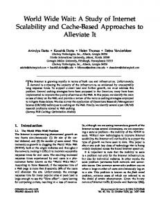
Simulation and Interface Design This chapter presents the details of a multiple vehicle supervisory control simulation and interface developed to study the effects of automation levels on human and system performance in time critical applications. Explanations of this program's functionality, appearance, and usage are outlined, and the rationale behind the program's design is offered.
3.1
Overview
In order to study how levels of automation affect temporal constraints in human supervisory control multiple task management, a dual screen simulation test bed named the Multi-Aerial Unmanned Vehicle Experiment (MAUVE) interface was developed (Figure 3-1) that allows an operator to effectively supervise four UAVssimultaneously, and intervene as the situation requires it. Using this interface for subsequent experiments, subjects took on the role of an operator responsible for supervising 4 UAVs collectively tasked with destroying a set of time-sensitive targets in a suppression of enemy air defenses (SEAD) mission. The simulated UAVs were highly autonomous, and therefore only required operators to provide high level mission planning and input execution actions to the UAVs. The UAVs launched with a pre-determined mission plan that came from an air tasking order (ATO), so initial mission planning to include target assignments and routes was already completed prior to launch. The 45
--
---·
CIW
runau..
_
,
UAV4
II~lnl
I
_I
_
Wnl
.... =;r-rs =. _=_
~-
Z_
UlraU*
.
.
`,
_!n
_
:
~
.
.
. .-
_=
..
I--_C,
a
_
x
^
__, ~~~~~~~ '
e: -
-
:u
!
,;-Pll111- --
r--l
·
^l
=-r 4 r UM 1........... ........
L-LT-b.R-_L
-.
Ai
_*
UM
.__ ,
·
_-- ~~~~~~~1.#
_
n.
... _
ll
.. ... rou-·lm·mlmr*rmrr*· L·)··)-H·m·rlll·1IIU·III(U 91CUI ·Ia···llr*rollrr·crl·llr uu· n*-· om.,eI rqrq r· CU*.-a, r,. a I-rca err WUC. 9- RIlwi luC·r· · iv. i; ·C 11 *1090 ICI1 · I·LL*1I ·IYLI)·nm glrlrrrr
Law_7 I'-
-I
_[ . ..
.
..
'.
ri o.rlLay-·EbP·LL1·LICL YI·116-lllrlU uulw-rrel11-u ururPrrn·r··ll·l·crr u*wulrrlrrr ULIILIIOIIIII-IIIIC( orr(ru-·rl··rr·rrr WILlrlll·IIIL w*ou-nr·Lnr luxrua-r*r·-Fu i Iil W*lltlLl)v*l(lHlllll VL1U·U· L*PU :u?3 Irl·u-n*,ul urrlltu)-4·ruur*·l.m .............
Figure 3-1: The MAUVE Dual Screen Interface
operator's specific tasking in the MAUVE simulation was to monitor each UAV's progress, re-plan aspects of the mission in reaction to unexpected events, and in some cases manually execute mission critical actions such as arming and firing of payloads.
3.2
Navigation Display
The UAVs supervised by subjects in MAUVE were capable of 6 high-level types of
actions in the simulation: 1) traveling enroute to targets, 2) loitering at specific locations, 3) arming payloads, 4) firing payloads, 5) performing battle damage assessment, and 6) returning to base. Battle damage assessment (otherwise known as battle damage imagery or BDI) is the post-firing phase of weapons release where it is determined
whether the weapon(s) hit the target, and if the desired effect was achieved. Table
UAV Action
Color
Enroute Blue Orange Loitering Arming Payload Yellow Firing Payload Red Battle Damage Assessment Brown Return to Base Green Table 3.1: Color Coding of UAV Actions in MAUVE 46
I~znr.nmm~··lllt~i u~nM
I
UA wCuWnt UAV 4 AHnHV
rm
~ll
End:
i.0Z714Z
MISION Elapsed: R TMlE:30Z TM 1000714o:.
1
,i
I
Weapo
Wiepon
MovemenWt
TWgetA9lgnmnt Tas
3
T_l
i
tXilL
Way Ponrt t WLok Pokb Lo
Poin
iL~ P~nt
I
/
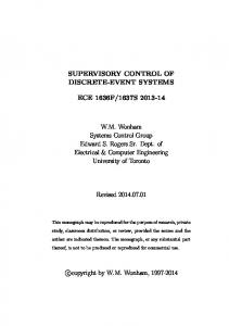
Figure 3-2: The MAUVE Navigation, Mission Planning and Execution Display
3.1 outlines the color coding assigned to each of these actions in the simulation. The left-hand side of the MAUVE interface is known as the navigation display, and it consists of a mission time window, map display, and a mission planning and execution bar (Figure 3-2).
3.2.1
Mission Time Window
At the top right of the map display is a mission time box showing both time elapsed and time remaining in absolute and relative terms. Due to the time critical nature of the set of targets to be destroyed and the large number of tasks to be performed while supervising four UAVs, time management and scheduling is the fundamental problem faced by operators in MAUVE. Operators are supported in meeting the 47
global deadline for the mission by the time remaining and end of strike timers, while the time elapsed and current time displays aid operators in meeting local, individual target deadlines.
3.2.2
Map Display
The map display (Figure 3-3) represents a two-dimensional spatial layout of the battlespace, updated in real-time. The icons used in the map display (Figure 3-3) follow the MIL-STD-2525B1standard
whenever possible, which is the US DoD interface
standard for common warfighting symbology. A legend very similar to Figure 3-3 was available for users to toggle on or off as desired.
The UAVs on the display are numbered 1 through 4, and they independently change colors according to the action being performed by them at that instant (Table 3.1). Latitude and longitude markers on the left and top sides of the window give the operators absolute location references. The current mission plan for each UAV is indicated by thin black lines, with arrows at the bisector of each segment indicating the direction of traversal. The thick light green line around one of the mission plans indicated that plan was the one currently selected by the user. For instance, in Figure 3-3, UAV4's route has been selected by the user.
Targets are designated by a diamond-shaped icon, and are assigned a relative importance to the mission plan (priority) of high (H), medium (M), or low (L). All
target names follow a naming convention of T-XXP, where "T" indicates it is a target, "XX" is a unique identifying number, and "P" is its priority. All target names are super-imposed on the relevant icon (Figure 3-4) and active targets are differentiated from inactive targets by their color, which is either red or gray on the display, respectively. An inactive target is any target that had either was destroyed or its TOT deadline passed. Waypoints, which are shown on the map display with black triangle icons, represent UAV turn points while enroute. Naming of waypoints follows the convention 1A military standard (MIL-STD) is a specification which lists and explains a compilation of prerequisites that an item must meet for US DoD acceptance 48
LEGEND
L3
UAV
*
Active Target
A>
Inactive Target
r'-- Base
A (
Waypoint Loiter Point Threat Area (b) Map Display
(a) Legend
Figure 3-3: The Map Display with Legend WP-XY, where "WP" indicates the object is a waypoint, "X" is the UAVnumber that the waypoint is associated with, and "Y" is a unique identifying letter for the specific route. Loiter points are represented in a similar fashion. The naming conventions are identical, except loiter point names begin with the letters "LP" and their icons have an additional circle around the black triangle graphic. Functionally, a loiter point is the same as a waypoint except that when a UAV reaches a loiter point, the UAV loiters for a user-specified amount of time before moving on. Minor adjustment
to
UAV routes on the map display can be made by selecting a particular waypoint or
loiter point (indicated by a dark green highlighting as seen at the top of Figure 3-3) and dragging it across the display to the desired location. More significant routing changes such as the addition or removal of waypoints, loiter points, or targets (together known as navigation points) is accomplished using the mission planning and execution bar which is described in Section 3.2.3.
Threat or hazard areas are always circular in shape with a striped yellow coloring 49
Name: T-9L Lat: 26:52:49.0
N
Long: 46:15:53.1 E ToT: 12:20:35 To: 12:20:55
Figure 3-4: An Active Target with Mouse-Over Pop Up Window
pattern, and use the naming convention H-XX where "H" indicates the object is a threat/hazard
and "XX" is a unique identifying number. Threat areas can be
dynamic throughout scenarios through either changing size, locations, disappearing entirely, or periodically emerging. Users can obtain more detailed information about particular screen elements on the map display by briefly hovering the mouse cursor
over them. While doing so, a small orange pop-up window appears next to the screen element (Figure 3-4) showing that screen element's name, position in degrees latitude
and longitude, and if a target, the beginning and end of its TOT window. The TOT window start and end were designated by the ToT and To headings, respectively (Figure 3-4).
3.2.3
Mission Planning and Execution Bar
Located on the far left of the navigation display, the mission planning and execution bar (Figure 3-5), supported the majority of human interaction with the UAVs. Each UAVhas its own mission planning and execution bar that is selected by either clicking on the desired UAV's status window on the decision support display (Figure 3-7), or on the UAV icon in the map display. As described in section 3.2.2, light green
highlighting around the UAV's status bar and its current mission plan in the map display told subjects which UAV and route was currently selected.
Mission Planning Through the mission planning interface, users are able to manipulate the set of targets each UAV visits (including order of visitation), their deadlines, and the path the UAV 50
travels between them. A key element in mission planning is the target assignment queue window (Figure 3-5). The target assignment queue lists all targets currently assigned to a UAV in the order they were to or did visit, so it serves as a time history and future prediction of all targets currently assigned to that UAV. Just like the map display (Section 3.2.2), inactive targets are grayed out in the list to differentiate them from active targets. Battle damage assessment is toggled to the opposite setting of "on" or "off" for a particular target by selecting it in the target assignment queue and clicking the "Target BDA" button to the immediate bottom right of the window. A check mark beside a target indicates that battle damage assessment is currently "on", or scheduled for that target. BDA is semi-automated in the sense that the operator is responsible for scheduling BDA in advance, but the UAV performs it automatically after firing, if scheduled. Due to the planned approach to this function, the user chooses whether BDA is performed on a target before the arming window occurs.
Subjects can also change the order that targets are visited by hitting the "Move up" or "Move down" buttons beside the top right of the target assignment queue. In doing so, the mission paths on the map display are automatically re-planned with straight line paths between the new set (or ordering) of targets. All existing waypoints and loiter points on the affected paths are deleted. The "Request TOT Delay" button allows users to have a limited opportunities to manipulate the set of TOTs they are attempting to meet in any given scenario. Subjects can request a time-on-target (TOT) delay for a given target for two reasons: 1) According to the current mission plan, a UAV is predicted to arrive late to that target and therefore miss its deadline, or 2) for workload purposes, i.e., if a subject
feels they need to spread out workload to manage the UAVsmore effectively. However, this function must be used with care because moving back one target's deadline affects a UAV's arrival time at all subsequent targets. Users have to be careful that they are not causing additional missed targets farther in the future in return for near term gains. This change of TOT is a request, not a command, and the request can be approved or denied. The probability of approval is a function of how far in advance of the deadline the request is sent, as would likely be the case in true military sit at i ,-, 51
The probability distribution for chance of approval is given by Equation 3.1. Subjects do not know the actual probability function but are aware that if they want to move a deadline, they have a greater chance of doing so farther in advance.
P(Approval) = 1.0 - e-t/450
(3.1)
where t = time in seconds before deadline request was sent When a TOT deadline is immediately approaching, the chance of approval is near zero, but nearly 1.0 when requested 15 minutes in advance, which is as far ahead as the decision support shows for higher levels of automation.
A request always takes
5 seconds to come back, and during this intervening time no other TOT requests for any other targets can be made. Users can request as many TOT delays as they wish for a given target, but there is no guarantee of ever having one approved. Requesting
TOT delays requires focused operator attention for extended periods of time, which can be problematic because it may be more appropriate to focus on another more time-critical task, such as re-planning a route due to an emergent threat. Targets can be added and removed from specific UAV's routes by hitting the "Add
Target" and "Remove Target" buttons. To add a target, subjects first select from the list of eligible targets in the pull-down box immediately below the button. In order for a target to be eligible to be added to a route, it cannot be a part of any other route. If a user wishes to switch a target to a different route, they must first remove it from one route before adding it to another. This was done deliberately to ensure a target could only be assigned to a single UAV. Frequently there are no unassigned targets
in the battlespace, so in this case the option to add a target was disabled entirely, as seen in Figure 3-5. The "Remove Target" button works similarly, the only difference
is that the target to be removed can additionally be selected by clicking on it in the target assignment window. The "Remove Target" button is primarily used to remove particular targets from the mission plan after a re-planning message gives orders to do so, but it is also used to re-assign targets between different UAVs. The "Add
Target" function is required when an emergent target appears, when a missed target 52
UAV 4 MISSION PLAN
LegendI
Weapons Movsemenl
Movements .oYe Nel TmgsT
RetuntoBase
TargetAssignment Queue Name BDA
_
R
2
T-1L
3
T.5H
4
T-~L
_
' I ^~II~BIPII Move up Movedown
43T5~-9
R'-
Req. TOT Delay
if
i T get BDA
| Remover.,et| T-15M '
//a Friltc
WayPoints AddWgPot
|
LoiterPoints AddLmelPant
Figure 3-5: The Mission Planning and Execution Bar
is added back to the schedule, or when an operator wants to assign a target to a different route. The final mission planning functions available to users of the MAUVE interface
are the ability to add and remove waypoints and loiter points. Removing waypoints and loiter points is a simple 2 step process.
First, users click on the waypoint or
loiter point on the map display that they want to remove, and then they hit the "Remove Waypoint" or "Remove LoiterPoint" button. To add a waypoint, users hit the "Add Waypoint" button and click on the map display where they want to place it. Based on the currently selected route, the simulation attempts to add it to the nearest route segment. From there, users drag the waypoint to any desired location on the map display. Adding a loiter point through the "Add LoiterPoint" button 53
worked similarly, except upon placement, a dialog box appears on the map display that asks users how long they wish to have the UAV loiter at that specific point.
Users could add waypoints to avoid threat areas, while loiter points could be used if a user wanted a UAV to remain in a certain area for a specific reason. One such reason
would be that the operator suspects a high priority emergent target might appear at a later time.
Mission Execution The mission execution functions available in MAUVE are arming, firing, performing
BDA (described in Section 3.2.3), returning to base, and moving to another target. Figure 3-6 shows a nominal sequence of mission execution events that a UAV performs
at an active target. The sequence occurs as follows: UAV 4 arrives at active target T1L before the start of that target's firing window (1), loiters until the beginning of the arming window (2), arms during the arming window (3), fires during the TOT window (4), performs BDA immediately after firing (5) and after finishing BDA, moves onto
the next target automatically (6). Step 2 might be skipped if the UAV arrived late to a target, i.e., in that target's arming or firing windows. Step 6 (performing BDA)
was not required at every target. The "Arm Payload" and "Fire Payload" buttons on the Mission Planning and Execution Bar (Figure 3-5) are only enabled if the rules of engagement (RoE) (Ap-
pendix A) of the simulation are met. For arming, this means that the UAV is directly on top of a target and the mission time is within the arming or firing windows, and
for firing it means that the UAV is at the relevant target, within the arming window, and already armed. In either case, the arming or firing buttons are not enabled unless the relevant action is predicted to finish by the end of the firing window.
The "Move to Next Target" button causes the selected UAV to start moving enroute to the next scheduled target, and can only be used in off-nominal situations. It is required because the automation rules governing UAV behavior cause every UAV
arriving at an active target to loiter indefinitely unless the user intervenes, such as arming and firing on that target. However, if arming and firing does not occur within 54
(3)
(2)
(1)
w~wu==!' ~~~4&-
Slr,
-
-Lr,
I),
I
(4)
(5)
(6)
Figure 3-6: A Series of Typical UAV Actions at an Active Target
the appropriate windows, then that target is missed and the user needs a way to get the IJAV moving again. There could be situations in the simulation where the RoE changes such that a previously designated target should not be destroyed, thus in this case arming and firing on certain targets is not desired. In terms of Figure 3-6, the "Move to Next Target" button is a way to go from Step 2 to Step 6 directly.
The "Return to Base" function causes all future targets, waypoints and loiter points to be deleted from the individual UAV's mission plan, and a straight line path for that UAV is planned directly back to base. It is used whenever subjects want to get a UAV back to base as soon as possible.
3.3
Decision Support Display
The right-hand side of the MAUVE simulation is termed the decision support interface, and it consists of a UAV status window, chat box, UAV health and status updates, and the decision support window (Figure 3-7). 55
__
[MS Current S Time
STATUS MISSION I
oomo. I. - I -
I-
10:00m
15'00
min
VIWA OWNIB 5alu:
DA
Alilur
10000SL
..
. Ce4s:10' Crel rTr4: T- 14H SpHS 200 lds Lallud 21:5914 1 Loltude: O6:0000.oE P 'ed . 0OalS . 1.17L
i. t
-2c
-W-29 Satus: Enroute
Curl
MIiu:
Teargtl:TH
LtawSe: 2 44 03 9
Loeitld:
046.25 00.8 E
1t0000 UAL
Cuse: 3' Spe
25o00 I
2
Pala Rea'.
0
. T.6U
T-7.
Satus: Enroult
AkI: 1
10000MSL
c are.n:
CaS
263'
Tar: T1
LAlie: l:.37 12 Spt12500 L.kude: 0o2: 0 3 E Paad R
T-15 t
. 3 . .
s 0o
74WB .
SIaIs: EnmUi
Albhlde: 10000 USL
Careit Tre: T-5H
Co e:180'
Lid.1: 21 09:44 5 t1 LoiuWe: 04403:30 8 E
Sp Pyi
.
T- X
.
...)
....
IE
4
2500 ts RRad:0 _---
T-M
..
·
·-
e
11
- .=T-IlL
r.,u
Messge...i.o.. t to moveLe TOT for T 17Lwasapproved Bae (12:01:20)-> Request Base(12:01:21) - New TOTfor T-17L s 12 160IZ - 12:16'21Z Oprator (12:01:59): 1 eldg in the mext miuntes 7 - Hlew reny tarts Iane ITOTs Ban (12:02:411) Op tor (1.2:02:55):5
-> WAih UAVs' sl Base a(2:05:25) inmsdiatly south-w.st (SW)of Bs Operator (12:06:03): 43
ittha plasm w ldhae tobe evised
H.2 matnd , SENDI |
i
Health & Status Updates T-16M UAV3 (12:04:55) Avaibble t fhlr tart UAY 3 2:04:55) - F.ng o T-16M UAV3 (12:05:00) -> Fiig compleedfor targd T- 16M UAV 4 (12:05:45) Aibble to annfor tet. T-4L UAV4 (12:05:45)-> A'mm for T-4L for targ T-4L UAV 4 (11:05:51)-> Anug complded ti hs fr tr t T-4L UAY 4 02:05:5) -> valb UAV4 (12:00:55)-> Fsngon T-4L UAV 4 (12:10:01)-> Fing completedfor arg. T-4L r t T-14H UAV 1 (12:06:25)- Avallleo arm tae UAV 1 (12:06:25) - Annug for T-14H U 1 (12:06:1) -> 9lnmg compidedfor tget T- 14H UAY1 (12:06:35) -> AvailaMe ito bfor arpt T-14H
' IAV
'UAV1
1 (U2:06:3) - FiringoT (I2:06:41)->
FrgcompeedfortargertT
T-4H 14H
Figure 3-7: The MAUVE Decision Support Display
3.3.1
UAV Status
The top left of the decision support display contains a status window (Figure 3-8) that gives the operator low level, detailed information for each UAV. This window shows
each UAV's current target, current status, position in latitude and longitude, course, and weapons information. The currenrt target field indicates which target the UAV is currently scheduled to reach or the target it was currently loitering at, depending oni whether the UAV was enroute or loitering. The UAV's current action field has a
description consistent with the color of the UAV on the map display (Figure 3-3) as well as the icon on the right of the panel. The payload ready indicator always reads either "1" or "O". If it shows "1" instead of "O", this means that the UAV has armed for its current target, and is available to fire. 56
Status:Enroute Currenit Target:T-3H Latitude:27:38:25.5 N Longitude: 042:09:52.4E
Altitude:10000MSL Course:45' Speed:2500kts / 1 PayloadReady:0 ... i:
Status:Enroute CurrentTarget:T-11M Latitude:2: 7:21.2N Longitude: 049:24:44.4E
Altitude:10000 MSL Course:239' Speed:2500 kts PayloadReady:0
Status:Arming CurrentTarget:T-4H Latitude: 22: 2204 8 N Longitude: 041 07:01.9E
Altitude:10000MSL Course:187-
Status:Firing CurrentTarget:T-1L Latitude:27:26:08.2 N Longitude: 049:44:25.2E
Altitude: 10000MlSL Course:5' 4 Speed:2500 kts PayloadReady:1
2
3
Speed: 2500 kts Payload
Ready:
0
'.
-
Figure 3-8: The UAV Status Displays
Speed and altitude are also shown in the status display, although they are not directly controllable by operators.
Each simulation is run approximately 4 times
faster than real time so an entire strike can take place over 30 minutes (instead of several hours as is commonplace in real life strikes), thus the speeds shown are not representative of true UAV simulated velocities.
3.3.2
Chat Box
The bottom left of the decision support display holds a text-based communication tool known as a chat box (Figure 3-9) that contains a time history of all human interaction. The chat box is an established method of communications in current day military command and control scenarios [6]. The use of a chat tool in the MAUVE simulation adds ecologic and external validity as a secondary workload and situation awareness tool [8]. The chat box window displays various notification messages that appear in re57
Message History Base (12:07:18) => New TOT for T-5H is 12:17:10Z - 12:17:30Z
Base (12:07:40) => Which future high priority target wouldprovide the greatest decrease in a single UAV's travel time, if removed from the ATO? Base (12:07:47) => Request to move the TOT for T-9L was approved Base (12:07:47) => New TOT for T-9L is 12:21:062 - 12:21:26Z Operator (12:08:30): 10 Base (12:08:55) => How many active medium priority targets remain to be destroyed?
A- I .
SEND
_CLEAR |
Figure 3-9: The Chat Box Window
sponse to scenario events or actions taken by users, as well as periodic task-relevant
questions for operators to answer. A scroll bar on the right side of the chat box ensures that subjects can scroll up to see a complete time history of all messages for the current session. The accuracy and time delay in responses to the online queries are measured to obtain an objective measurement of situation awareness as well as secondary workload, or spare capacity.
Messages in red are from intelligence com-
manders and always require an immediate re-planning response by the operator. An arrival of one of these high priority messages is signaled by an audio alert to ensure operators were aware of these events as they occurred. Messages in bold black are
questions about the current situation from a remotely located commander or superior officer. A response is required, but is a lower priority task than supervising the UAVs. Messages in plain black are purely informational messages that do not require
a response. One informational message that is particularly important to operators are notifications that TOT requests had been accepted or denied. If a TOT request is denied, a pop-up box appears on top of the map display, an audio alert sounds, and a message stating the denial appears in the chat box. If it is approved, the requested target's TOT is moved and a message stating the approval and new deadline for that target appears in the chat box. 58
Health & Status
dates
FUAV2 UAV 2 UAV 2 UAV 2 UAV 2 UAV 1 UAV 1 UAV 1 UAV 3
(12:15:19) (12:15:25) (12:15:26) (12:15:27) (12:15:33) (12:21:26) (12:21:26) (12:21:31) (12:21:31)
-> Arming for T- IMM -> Arming completed for target T- 11M -> Available to fire for taret T-11M -> Firing on T- 11M -> Firing completed for target T-I 1M => Available to arn for target T-13L => Arming for T-13L -> Arming completed for target T-13L => Under Fire from threat H-2
UAV 1 UAV 1 UAV 3 UAV 1 UAV 3 IU V_3
2:21:36) (12:21:39) (12:21:42) (12:21:45) (12:21:52) (12:22:02)
=> -> => -> => =>
Available to fire for target T-13L Firing on T-13L Under Fire from threat H-2 Firing completed for target T- 13L Under Fire from threat H-2 Under Fire from threat H- 2 ._~~~~~~~~~~~~- - -- -- ,
--
---------,Nw _,A _e..^A_*. ,_, _, ,A,,__ ,,
Figure 3-10: The UAV Health and Status Updates Window
3.3.3
UAV Health and Status Updates
The bottom right of the decision support display contains a notification window similar in appearance to the chat box (Figure 3-10). The health and status updates window separates human from system communications, and therefore only contains messages from individual UAVs. This reduces clutter and confusion about the source of incoming messages in the chat box window while still allowing the system to notify the operator of important changes. The system generates three types of messages in MAUVE: 1) emergency health messages in red, which are accompanied by an auditory alert, 2) important status messages in bold black, and 3) lower priority informational status messages in stan(lard black. The emergency health messages are generated when a UAV is under fire
from a threat area. Higher priority status messages are automatically sent by UAVs when they are ready to arm and fire, and the UAVs also send lower priority messages informing the operator of their status during all stages of arming and firing. 59
3.3.4
Decision Support
The decision support, represented by timelines, always appears in the top right of the decision support display (Figure 3-7). The manipulation of the appearance and functionality of this window is the primary independent variable of the experiment that will be discussed in Chapter 4. There are four possible forms of decision support in MAUVE that represent levels 1, 2, 4, and 6 on Sheridan and Verplank's levels
of automation scale (Table 2.1), termed manual, passive, active, and super active respectively. This section will discuss the functionality and rationale behind the design of each of these levels, but leave the experimental design details for Section 4.5.
The basic premise of the decision support is to simplify standard air tasking order (ATO) data and combine it in a single interface with up-to-date mission planning information.
An ATO provides a schedule of events and required resources needed
over a period of hours and/or days for an offensive attack. Examples of information
contained in an ATO are which aircraft/UAVs are assigned to certain strikes, times on targets, waypoints that must be flown on those strikes, and call signs to be used on those missions. As air tasking orders often involve a large number of aircraft with multiple missions, they are complex and often hard to interpret, particularly under time pressure. Despite this, operators are still expected to extract the information they need in a timely manner. Figure 3-11 shows part of a typical paper-based ATO from Operation Desert Storm that illustrates how difficult it is to extract relevant information from these tasking documents. Once operators have obtained this information and the mission commences, they must constantly compare the current and projected mission status to the ATO and make adjustments to ensure compliance with mission requirements. Combining these sources of information, which often include external sources as well, is a cognitively demanding task that can easily overwhelm operators
under time pressure, particularly when supervising multiple vehicles at once. It is for these reasons that the decision support in MAUVE is directed at simplifying this process. While it is known that some level of decision support is required to more 60
~~~~~OPw/f)tlSR 5TOP// tSSO/M*ESP/CTG IS lV/IS9//b./ RtPAroi.I#/jChNt F .gttr3e4aSte5V*IJ PJAItt SKZbkC QOi// AI08kTyC KlLOI AC6, C*ItC&L EAPGO&qOD t'lACKI// "tFA4"iWAI CftALftJ$,#/l St0/1O"sO*c s03lI, e343t, 434S0, *5tp, 0 * 13It/ t V¶ASKtC*eS /1SZS ISZ* be66lleZJciC',I/ ftiDCt4/tRGCT STnUCK-3lG"fTEt/ /.1/
-A.qiadT-Re737RiE/~Y4Alf RuCKS 05 -/2l9£3*h36 ?3l6lt/1RUC3S.IT
/eZ/
st./
-t94)3s CtP i/7)SI5PRDiLtiE TNC3l
AVPhN/T"E SvtKE
PACKAGEFLE XED C Tf
OPtrrI t
LC',..
"'D
4O TUtt g {AGCKS.'/
?f
Co
E[i IFC
Ct!S.
1O
CWC'G *,,&GCO#
1- 4-. -A,
9
1E400S&
TSTA&rGt T% TCO LLCX1 A
twEt? AEt COA3F1StEO or CS4ILOE Cof"JiCT
' I52S COCPILt Eli/#lM* OA& I or PA
DECLASSIFED ON:18 OCT BY: DONGWDP AW OPNAVNST613. SERIES
-
tWLL
3ST*P8
*4i
iKPC
,rI-I'1AL
10 C 0
15
C
CC
$NAVC
iC
NGUv!P .*,/ .I-"C
._ .Ct CMrCt
FP!
*'
WM9
UNCLASSIFIED
Figure 3-11: Example High-Level ATO Document
effectively manage ATO information and scheduling, it is not clear what level of au-
tomation will provide the most improvement in overall schedule maintenance while avoiding negative side-effects, such as a loss of situation awareness. Therefore, four
versions of the decision support were created and structured so that higher levels of decision support expanded upon the features found in lower levels while still retaining all of the functionality and basic information content from previous levels. The fusion of basic ATO information with current mission planning information resulted in a decision support structure with both hard and soft constraints. As a mission plan is continually modified by operators in response to events unfolding in the battlespace, it does not necessarily have to satisfy the ATO, so the decision support was designed to compare the ATO to the current mission plan. Hard constraints built into the decision support come from the ATO and include such information as the set of targets for the current mission, the TOT windows or deadlines for each of those targets and whether or not the target requires BDA. ATO elements can change occasionally during discrete re-planning events, but as far as the operators are concerned, these are static elements not under their control. Soft constraints on the mission can be directly manipulated by operators and includ elements such as 61
the set of targets each UAV is due to visit, estimated time of arrival (ETA) at all navigation points, and whether BDA would be performed at each individual target. This information is shown separately for each UAV.
Manual The manual level of decision support (Figure 3-12, LOA 1) presents all required ATO
and mission planning information in a text-based table format. Under the "Current Target" and "Upcoming Active Targets" headings, current TOT windows and ETAs for up to the next 4 targets in queue are presented next to each other for easy comparison. ETAs for arrival back at base in the "Mission Finish" column are listed as well as the next waypoint or navigation point on the current route segment (if applicable) under "Next Waypoint or Loiterpoint". Further assistance is provided to the operator through the "Next Expected Action" column, which tells the user what they should be doing next and at what time, according to the ATO and mission plan depicted on the map display. All of this information is updated dynamically to reflect changing ATO requirements and mission planning changes initiated by the operator. With some effort, all of this information could be mentally constructed to create an accurate future schedule for each UAV. For example, in Figure 3-12 the decision support for UAV 3 tells the following story: UAV 3 will arrive at waypoint WP3A at 12:05:48, before moving onto target T-12L and arriving at 12:07:41, almost 1.5 minutes before the start of that target's firing window at 12:09:15. The next two targets in the queue are T-4H and T-10H, and the UAV's current ETAs at those targets are both before the start of the applicable firing windows, so this UAV currently is ahead of schedule. Assuming everything goes according to plan, the UAV will arrive back at base at 12:26:10. This level of decision support is termed manual
because the automation does not take any decisions or actions for the human. The ATO is simply organized in a digital format for easer reading as compared to a paper version (Figure 3-11). 62
UAV
CrlretTg-
. Wi W---|;
TOTIETA
o Loitlr'poil t
- I:ciki
- -; -
-
-1 125.55Z106
T-12L
4
12:09:15Z
- 1.09:35Z
'1207:412
T-17M 12.0.0052-1:'.08:25Z 12:07:53Z
F
1213:55Z-12.14:15Z 1218:10.Z-1t8:30Z 12:13:22Z 1217:27Z
-105:55
T
12:06:35Z - 106: 5.5or
. -
T-13L
T-3H AiniforT 1205:45
T-16H
3
Ai t bn TOT/ETA
r-6M 12:05:5Z--1:06:15Z 1205:34Z
2
t
-
12t
T-4H
WP-3A 1054
Armingfor T-12L 0905-1035
1
T7)-4A
Armilg
T-IL .11:15r 1:10:55Z-1
12:06:46Z
12 07:55 - 1208:25
for T-17M
T-11M
T-14L
1215:25Z - 1215:45Z 1 14:56Z
1210:20 -1210:40Z 12:09:49Z
1:5 12:10:2Z
Z11:05-111:25Z
12:11:04Z
7
12:23:36Z
T-SL 12:225Z-122045Z 12.196Z
T-IOH
11t5Z IBase 118.55Z - 12:19:15Z 12:18:11Z
T-SH -2:16307
12:160 12'
5:42Z
2:23:00Z
1 2:26:19Z
T-9L 1.20:35Z-12:2055Z I1 Xf,
Base Base 2:2
Figure 3-12: Example Manual Decision Support Window
Passive The passive LOA (Figure 3-13, LOA 2) takes all of the ATO and current mission
information contained in the manual level and transforms it into a horizontal timeline format color co(led by action (Table 3.1). The major difference b)etweenthis and the manual level is that the entire schedule is visually integrated with both color and iconic representation.
These are display design interventions that reduce cognitive
load by allowing operators to directly perceive relationships instead of deriving them through calculation, inference, and data transformation. Spatial relationships and actions are understood better with visual representations as opposed to linguistic [37], thus this passive display should improve performance over that of the manual display.
The visual timelines are relative and represent time up to 15 minutes into the future. Figure 3-1.4illustrates the standard elements of a representative visual timeline. As can be seen from the diagram, target ETAs are represented by black rectangles on the bottom of each timeline, and waypoint, loiter point and base arrival times are 63
'Curre T-im
5,00m ..
-6M
T-7H
T-1 6H
:-.
mn
'
T-3H
T-14L :
-
5;00mi
T
T-11M
T-8L
WP-3A
Y4-3
T- 2L
T-1OH
T-4H
4
I
j
T-17M
T-L
T-9L
Figure 3-13: Example Passive Decision Support Window
marked by black triangles on the top of each timeline. ATO elements such as target
TOT windows, arming windows, and times when BDA is required are represented by red, yellow and brown blocks of time at the appropriate times.
With this visual representation, recognizing problems with the current mission plan becomes a process of comparing the relative location of display elements instead of specific times to one another. The visual task is much easier and faster to perform because it only involves perception, as opposed to the cognition required to compare the ETA and TOT numbers to each other.
An example of how users recognized
problems with the mission plan using this visual timeline is as follows: in Figure 3-13, the ETA marker for target T-5H (assigned to UAV 4) is entirely to the right of
that target's firing window. This means that UAV 4's arrival time to T-5H is after the deadline for that target, and a upon seeing this, users knew right away that they were going to miss that target and that they had to act to change this. Another emergent feature of this display is that if the color of the UAV icon to the immediate left of the
timeline is not the same color as the current timeline block, the operator immediately knows that the UAV needs attention, as this means that the UAV is missing a target 64
.
..
\
/ .
T-1 4H -
Waypoint ETA
Firing (TOT) Window
Arming Nndow
.
lk
-
-1A
T
A. ,* . . .* Jo
WP-1B
x~~~~~~~1
k
I
.
.
Base ETA
\ \
Loitering
\al . . ...
.. ...
I
T-17i
_DD BDA Scheduled
Enroute
Target ETA
Returning To Base
Figure 3-14: Representative Decision Support Visual Timeline
deadline specified by the ATO. This level of decision support is termed passive because
the automation is not performing any tasks except transforming the basic ATO and mission planning information into a graphical format.
Active The active LC)A (Figure 3-15, LOA 4) uses the same horizontal timeline format as the passive automation level, but provides additional computer aid to the user. In this version of the decision support,
an algorithm searches for periods of time
in the schedule that it predicts will cause high workload for the operator, and it directs the operator's attention towards them. The computer identifies high workload areas, or "bottlenecks" as periods of time during which multiple UAVs are scheduled to be simultaneously executing mission critical actions, defined as arming, firing, or performing BDA. The automation draws attention to these areas of concern by a reverse shading technique, in which the "bottlenecks" are highlighted while the rest of the timeline's colors are muted into the background, but still visible. As no information is hidden, only made less salient, the operator's attention is directed to the appropriate areas of the schedule while allowing them to maintain SA for the rest of the mission. This technique also does not require any drilldown to subsequent 65
Current Time
-": ",-'" -.
1
5;00 r min vI"-l
A
:Y V
'10:00 mn . -
.
15:00min
.
-.
-1 B
s., 1
Base
1
RECOIMENDATION , I
:
I
~~ ~ ~~~~~~~ ~~~~~~~~~~~~~ I I~ I
I .
I
I
'
'.~ l
T-9M I
..
; 2
~
~
~
If 1@
v'.-'
-2-Z
o
Ia
.
I;.
. , ,,, ... - -
- T-7M
I
-- .i
T-1 OM
T-1 7L
~
~~
Request TOT Delay for, T-1t7
:,!
Li,'
T-15H
I 3,
I i-
;-'- !.......
r~~~un~ I
t
a~a
RECOMEDATION I'I
Request TOTDelay for . p
a~ |
.____________________________ .j . __
49
:
1 -sw
!.
~ ~~ ~~ ~ ~ ~ ~~~~~~~~~~~~I
T-]H
Request
TOT Delay -4L T,}
T-1M
Figure 3-15: Example Active Decision Support Window
screens to solve the problem, so it permits operators to make local changes to alleviate workload and immediately see their effect on the global mission plans of all UAVs.
In addition to identifying areas of high workload, the computer also recommends a course of action to spread out the operator's
workload, such as the delay of a
particular TOT. Computer recommendations appear in gray boxes to the right of ;'.:'IJ
UAV's timeline that they pertain to (Figure 3-16). It should be noted that
while the automation makes locally optimal recommendations, the algorithm is not globally optimal. In other words, followingthe computer's recommendation to relieve a high workload area always removes that particular schedule conflict, but somrnetimes
it creates another in the process. Schedule changes to relieve areas of high workload are requested by the operator if they so desire (Section 3.2.3). The active level of decision support gives subjects several options: 1) they could acknowledge a high workload area but take no action,
2) they could follow the recommendation to relieve the projected high workload area by shifting a TOT, or 3) they could make other mission planning changes to ensure the high workload area does not occur in the first place, such as removing a target 66
RECOMMENDATION Request TOT Delay for T- 7L
Figure 3-16: Automation Recommendation for a TOT Delay Request
from a UAV's mission plan.
If all high workload areas are taken care of by the
operator, full color is restored to the timeline and the automation looks and acts like the passive level of automation until such time that a schedule change creates a new
high workload area. An approved TOT delay request causes the deadline for the relevant target to automatically
be moved back in one of the following ways: 1) 30 seconds, or 2) lI:H
enoulgh back tloprevent that target's arming, firing or BDA windows from occurring
in the same time period as any other overlapping targets. For example, if a target has a firing window that overlaps with two other high priority targets assigned to other UAVs, an approved TOT request for that target would move it back 45 seconds or
more to avoid the start of that target's arming window overlapping with the other targets' BDA windows. In this way, TOT requests occasionally move a target's TOT window back a minute or more. The algorithm also ensures that deadline moves do
not create conflicts with other targets assigned to the same UAV. The purpose of this level of automation is to help operators to identify time periods of potential concern where they could be overwhelmed farther in advance,
so that they can better plan to avoid them, or at least be better prepared to handle them. This level of decision support is termed active because the automation narrows down a set of possible solution alternatives
for high workload problems to a single
recommendation, consistent with Sheridan's level 4 of automation.
Super Active The super active LOA (Figure 3-17, LOA 6) also builds upon the passive level vi-
sual timeline, but instead of making recommendations to the operator as in the active LOA, a management-by-exception approach is taken whereby the computer automat67
CurrentTime
-5:00
min,
.
m m
15:00min
I'...
I
EXECUTING3
..I'.'I"I __ I
Arm Paoad · T3H 12:16:40Z 22 Seconds CUk to Cancel
M r-311
T-13LI
LI
2 -2>
1
-"" -11M
I-8L
33 I -u I
II-
iIl 1
4
L T-S1i
Figure 3-17: Example Super Active Decision Support Window
ically executes the arming and firing actions for all UAVs at each target, when the rules of engagement for such actions are met (Appendix A). For example, in order
to fire, a UAV has to be located at the particular target it is due to fire on, already armed, and the scenario time within the TOT window for that target. It should be noted that there are no special rules of engagement for the super active level of aulltomation; the computer follows the same rules for humans in other LOAs. In this
way, responsibility for executing routine arming and firing actions is removed from the operator, rendering the computer recommendations of the active level unnecessary. However, the operator is still responsible for determining if the arming and firing actions are appropriate, and for re-planning actions and manipulating routes to ensure the UAVs arrive at the correct targets on time. Up to 30 seconds in advance before every arming and firing action, exception boxes (Figure 3-18) appear to the right of the timeline that allow the operator to veto these actions. These exception boxes show which target the UAV is due to fire on, which action the UAV is preparing
to take, when it will take it, and it contains a countdown timer that indicates how many seconds from current time that the action will be executed. The color of the 68
EXECUTING Arm Pay1oad - T-3H
12:15:ZZ 22 Seconds CUck to Cancel
Figure 3-18: An Arming Exception Box Under Super Active Automation
box redundantly indicates which action the UAV is preparing to perform: red for firing and yellow for arming. This color also matches the next timeline block in the relevant timeline. This level of decision support is termed super active because the automation
is performing all of the mission critical execution actions for the user.
Summary Figure 3-19 shows the progression of the decision support window as the level of
automation selected in the MAUVE program moves from manual to super active. -
7
_-:;;:·--
--
amnlksmn*I
_
w
I
2
I 1
SR
I
__
:1
__
-L
-I~L:
_
,
If
Ir
1
~
I
__
[1~ L J
.,, -
,T,,] - - .,,-
:",
Ttn _
aGorn
I
r
..
v
_._ _ _-
novn.
i ..
_
....
.
3r l ___ ~
r
Rlm .
..
__
|
..
_
_
_
I
| __
.
_
13·rv~Tir 3 *·
1
I
l
1
g[
_.
_]
I
-::fB1;!11>
4
_9;~~ II I "-:-
',,?
i
II
i Lr
)
i--~~~~~~~~r
.l:t,3
1·11
401
·
-
---I
'4~~~~~·
WayPlint
Lolter Points I ___.___
(a) Navigation Window =.~n~~.
_.
_ I
r I
MISSION STATUS
l~l
·
_
~
Ut~
.1
,_aii
-
Sluan Enoule JUlbm (oooo 14SL 0U l g.: 7 l s** U:a C ... L4.15 1144233 i psr.5003LI4 *_5 0/' * '5 E P/40 rr 4_a~r
II__
curnrrnme
;:aom
.I
-I
1000omn
&:OOnDn
1 .
........._.
_.
....
rm
I.m
lJ
silul:Enroute _ I loIooiI~L CLf4 15144-1H Ceu5 104I' umlldm: :' ^*J ?Z r spe e r . s 2 LimA S45 3s4 E P Rd r 0 ....... i lrjn iTl: Enrldi Clurr age T. u4mr00O5n 2055.4. 015oO Lrllle0
o01o
_3 0000 uL srnrMrru1 49· 2O
~o$E P.4:500c 41
Cmm Iea T-IT~U Lr11 a 303r L5l4 0 4040$30E
Clzrr, .0 ISlie4 4 2541yu
P5d1 Rl4s 144.4.............. 4144;44
I 1ZL
r.r.
,370'i
r llu
W---
1 ,,
'i .
, 4
,:440
1
l' r 41 L
Mesage Hiatory
T.I
Healtt &Sttu
Updates
I___I
(b) Decision Support Window
Figure I-1: Super Active and High Re-planning Example - 12:00:59 170
Curent: 0209
UAV 4 .I
MISSION PLAN [L
IIl
End: 1023000
I* mi l
ilil }
I:1:1 ,
MISSION
Elspsed: 00009
TIME
I1zI1
I
I
|
I
11, 11(1, "J :l71
I 11Ag
Rmining: 00274
I
I
is
I
.r ln I1
Weapons
n
i,._____-
'1,
I
Movements i
~
l
_
//
I
166X /
X
Tiget Alnment
gE~ 111
ueue tfunle BO
2
T-IL
3
1T9*
*
J I__ 1-- W~
T·9
Way Points
I
L-cer-o
Loier Point hIr
eF-- n
(a) Navigation Window IIm
~
z
I-.11101
.
MISSION STATUS
LetDol Ent
26441:
EE E Cauroni 1s0 ,ri DII -l 1ee040 330414
0
l54alEm4t2 72430
.
uConreoTome
2.75e'. l
P
oue (0:01:00) Wbkb OF.e_ (12:.1:_:
0Nn
_
I
06: 0
AY's w
0 ooOrn'
,S
pwyN so IPW. 0 4 0_= .0 P 4od.s .. 6 . .:H
4
so m -. r:
IMS',
-r
F.
U
l60
st
a Bt
s
by
r,19
12::U?| ItgasiO
IL
IL
|
15
EiO;0
I' aLErR
'
_
(b) Decision Support Window
Figure I-2: Super Active and High Re-planning Example - 12:02:19 171
1
........ ...I.- , . .::,. ,
End:
MISSION
1
2 Z '3000
TIME IME
I
I
CurLnt:
UAV 1
I
MISSIONPLAN
I-05341 "1Z
I I
I
I
Elapsed:
Rmnkng:
5 1 :00033
04' 002424
1
I
I
r
I
I
,
Wponl
Movoments jOo100molaoOJ
7
TargetAlllgnmmnt Ei3
uue Ne 1
?
140
2 T-H
-
.__
f
II_
__I
____
WI
_:1. I'll11
_ .16 ---_
LJ.04000
|'1-1
I
r-rl
Way Points I
dw\,4
I
Loler Polnt -k
L.-P
(a) Navigation Window
MISSION STATUS
l : o eLOJI Liru .5d r 000 9II, LrOII a2'77E
|'
'
C
rTln,.r
oaOmn
"'
P o aL I1 ' 1 Sll_ ':s oH wu P~IV: *. "
-
.
..
-
2O:
mn
ftou0
221rs
.n
Tn
1
oinlsri m T-106H Cmm 104' L6e 2:$9 1 S3 N1 -t? .~00 U L0'14. 04844 2 * E PW/IdM 0
2 _ I-11i
Ooo L , ns 0 Co : Caum Enslm C~l IIllll: T-I 2L Ct 218' : , 3'i 5 500ts LnU:. 24040 4 6 IJ LCo1:bi0 G420 3 0 E P 0_
Mllr
IM1C T-I L
Lmzml
04T'.574
C(
I1L
T,11M
' O-
os
E P~Rem. *f
..................._._ (2:S1149): 4
Ll
F[ L111 i
r.ilm __... Opmr
l-L
r
l (1:02:20 -> Whir IaVJ M (0SIa! B5am? nt-Mu
s1
r·.s
Hsllh &Stus Updles
....
I'
pl-
,I,, -
4r r.
of thIs
1-3
oDd hm
UAV 3 (12:3:45) -> UAV 3 2:03:4) -> UAV2 {].2:3:7{ UAV 3 (123:03:5) UAV 3 2:13:") UAV3 .2:4:5) -.
n
Oimr ::2 03:); 2 -IL oppre s r TOT B 0a2:4:31)-> Requ to moiOe ohe B (1 24: 1) ->N TOT for T IL I 1122:1 · i2 12412 B (12:04S:4 : -' Re L da TOT f0 T- I7Mdainl
AVnI mre lar fte T-2M Amog TM Aan2 4-: og c308 44 fieo0,0t T-2M AnBAeb b N.otp T-2M Fi ll T.4M Anoin o T o- L .T M
UAV4 (12:4:45) ' A.Mg
I _
m M
T-II
UAV4(2:04:B5) -> Aovt o 1 fOs -gt T-I .M AV4 (ilo:ed:m) -> rrn r. T M UAV 4 2:0S:O) -> Fio m-o4;t 3 fo g, T- 15M niJ-R
(b) Decision Support Window
Figure 1-3: Super Active and High Re-planning Example - 12:05:34 172
s
III
I
End:
MISSION
Elapsed:
1230Z1 a73
TIME
0.07391
Cwrent
UAV 4 MISSION PLANI
L_
I {Jiui".
I !. 1}l
fil
I i~.1i} L.:1
I { l
I Ic Ih I
I ;.
ld 1i I-
Remaning: 0.22 }
.!;k F :
1 n
Weapons
..... . Movemente
TargetAldgnment ueue0 '
5r $
Ime
l
4
T-tL
r
M
j_
Way Polrnt
:1
1.
--
"`
Loiter Points
`-t i
_d__P4
(a) Navigation Window . .f MISSION STATUS
Lldr. Les0
-
t
I S r: I500 2304 I 1(,l41412 E Pa4.4I0. *
I
CurrTlT
-
1 _.., _l
AI0daLIOO004 210. Se4:10001 PTI.adOIO V
C: Pa Pl
.
latO1nR
;
IL0Oh 0
r
1-1TN---
· 3 m~~ I(
. r-L C.le Le.004111471101 trwIl b ) 47 5 r I
-
-Li
11"fl,
u:Enrue 1 Q goo M L, Cal4 liW: TlL4 CeIse ;50 2 lOIle - r 2 "4I(4 *Ea Lue de Lmgl l 3ll:0700 Pq4a.T Re4 0
0*43010)01 C-ao..0i.eo 1-2C.. Lad.12.11294 I o '4 4171,-
5or,
1 ..
..... . _4_4alt 1 9 Ii-_ _
T-
II
Iff-
P.ln
I
rr--_
*.4
I4L
fi
~ E ruI ~ ~dT |
i
li T-I.
sU
Health& Statu UpdMt. S1an126:4t)-r Bae 12:4t:1) -> Be l:6:9}) -), Bs 2:0?:M) -7 f 12:l:l)-> fF_ 12:7:I) R-> 1 (12:t7:24) Brae 112:7:24)-> BY 12;07:3 -, Ei_ ->
uAv 4(12:B:551)A v llm i 1r l..tS M UAV 4 (12:455) - Fenq er T-ISM fr tL , TIsM corlM UAV 4Q2::L01) -Fg UAV1 025:45) -, A e 18ot_ Ir qpt T-.M UAV (122:1: - Amon fo T UAV1 a112:55;1-> Amng -ompldd fo eg T-6M UAV I 2:i -o A.l4 m 11 Ir 1 7-CM UAV1 (12e5:55) -r Feg eu T-a UAV1 02:lM:Be-> rrm4gcrEored l he ge0T-6M lrU T-lIH UAV2 (12:6:2).4 UAV2 (12:6:;25) -, Afro or T-16H UAV 2(L2:0:29) - Ama. coUlde forWrge T-16H UAV 2(12i::) -> A v I fr lt Lf T-16H
o TOT 1f T.3. 121425Z- 12 1445Z Ptqul , moe -h TOT T-3H wu -pove He TOT fr TI s2 1 56Z. 1 16 16Z F eq lto m e tc TOT f.r T- 3L wspproved lNe TOT f4 T-13L. 1218:40Z. 121900, quest to deay TOT ft T 13L de RestLa ,omethe TOT r T-!3L l apoved tew TOT fot T. 13Lu 1220 11Z 120:3 IZ R uc'l rnase he TOT for T-SH T' appove d HI:0?: oTOT e T Ft 12:17.20 1746Z
{a1
uUAV . 2O-.t:36)- Fig e T-IdH UAV 2 12:0:-42Fn -ompetl fO. .rg T16H
(b) Decision Support Window
Figure 1-4: Super Active and High Re-planning Example - 12:07:39 173
.or-
r
:,..
':
::....;..
I. '-
-j
r
'-J-j '.
Cur't:
UAV 2
I
I1208140 -
III
1l
MISSION PLAN I
I
End:
MISSION
I 121-a0-0Z 2000Z I
TIMI1 TI
II
I.
-j
1
'
:
.
. ... .'
-',
-.
EHipsd:
1
Il"I,.
I'lI
/
.I
I
1.I'I
1
>1;
I -~
I~~~~~ /
.
Remng:
I
Movements
....
r-CIOO2ltr 21=6
00.045
I 'i15
....
~ ~
I
TargetAmlgnent Oueue Name
BDA
4
-i ',Cr
T.
"- -i
,
>~_ 1I/
I.}
rr ll /d~~~~~~~~/7
WayPoints
,,
",~~~~
Loer Polnt
I--~?=, _
(a) Navigation Window ·
MISSION STATUS
I
t
I-ITILI
Cugrnttt irr
l-tIe: -?H COiire: -urQ 1o L7f2lldll 16 11 p . * U 7 E P l/eiR nr '-e',S'i?
I5000 - __
·Pt
0101W o
'
__
_
--
,
I
-_T_
LSaU40flJ:1 1lesla 4:-7 7 L LIUc ?~03 ~1 8II Lmlm0ld J ~8' 9E
15elIK !eud0000 2.. P 1t S~leedC :~O Zs'/" P~aaiP N iq4K.iC, 0
slMm Lolr CeliraeFeT-L L-t.~.15UI2U
luw~ 1eOOoIL CIII SCa./ 21000
L..a.
P
L, iU,
R
I
· ···-
·-
.*Is*
J
Cul IdT-IH C~Inls 1,1 LItV: 2704.2 5 S e1 Ul Wf Lllldll.0.UoI0. J 0pt.sa .*
_
... T i~~~ruUE -rrlu~111 · · ·-
:41 214.7E
W~ =
4 "a0 . IN-l
.......
I. 00 nn
10m:o.700
Ht.Ith & Stdl Updltes
M..sa.a Hi. t....
Bae(2:0:t6) -> Rupste ,omoeronl TOT (or T-SH SO lved Oa2:t:36) - Ns TOT fo T-StUi 12.17.26Z- L2:1746 O :O?:107)-WlWlh f.eflar ho prl4 setopi ..U ity UA. -u. ltb-, Wro ft.om b ATO? b (12:0:12) - Requtt to m-v Il TOT fr Ta, appr.d _ G2: l :{2)-' N TOTIt T.9PL. 121,06. 12.21.26Z Or(2:O7:/) -' Requ ntot o0 l k (12:I:t)-, liraTOl T0117il 2p)nm (r2:01)4: I0
e
elet -d
4
TOT f T-L s pprod I221:360 12:1)567
J 1 lU7O
j
UAV I (12:0:SS) AV . b . iI Wrurp T-d, UAV l (l:05: - Fr: T., . Eils UAV 1 2:6:d) - F comIch g' T-tM UAV (12::2 5) F-AOes fret'105 10um, 1-M UAV 2 O2IA:25 -' Aamoi fl T6H UAY tlal-6:2-> ArK j c-o f g. T.IrI UAV 20.1I:M)-) Av4*b tob b tmatT-6H IUAV2(12:6:6)riemn TI UAV2 21:06:42)- Fr 8 compiled t 0.U T -I HTM UAYV 4(1t:s) -> AatlMI e a uprgtI UAV 4 (2:71575) Aa fo TT-11I e l m ' U4 A (I2::{{1)> A4 g -cp q4 T 17M UAV (1::l05) - Ao e lb. fortmoptT-1T7M UAY4a 1.:05) -F ig n T- 17M , (12 utA1r - np.. i-m .r11gT11
(b) Decision Support Window
Figure 1-5: Super Active and High Re-planning Example - 12:08:54 174
CCF
II
I
·
1
MISSION PLAN
L-
I
I
MovemenSt
_
I. I
I
; .11,I
j R° 4
"0 d
,
,ME2
I
I. d
-
Remilning:
0° '
I
1- 1 1. h
I-I
1 1 00.19.3
I
I
I
: nli1rE
I
4.; ,101
.
~~ ; I- '
I
I
I'-r
,:
-- __._
I.e.
Elapsed:
I
..
.7.._A. II
MISSION
I. .1r F
1
I
/
Targe Algnmenmt
·
t230.00Z
V12O114 I
I l.;, i Weapons
oeosE _1J j
End:
Curren
UAV 3
I
.iF . -
.. ,
S
,
4
_i--~Y
.iii
T-18L1
_~~IIEP
ti'
i
_
._
/ /z
...........
~~~~~~~... 't~~. * \
~.l
-
-
WayPolnt
Ior
r
r;,,,,s
.
. i
-·~~~~~~~~~~-'~-
_-
PolmI
(a) Navigation Window ,,I
MISSION STATUS
-,
1r. ule
S
ce_.I C P
-deO -' rIle:,04rl,0 :DOE
L
CUl5-5I{I L ud:. 2LacT:J0a7
.1-L
rd
.difI 13H ' . ..
t
* '
oo rn
&l
:
'
.
I 00mn re
-
''
.
",
.
A-
':"
-:E
-
,,
io0,
.
ij
IS'00lb
'-LJR~-
3
. a R."
C 1 SId:._-l2s Pi!~
i31JI I
I
I CurerTIme
i
. ,
I-:
FLUNL -IF C_
2 2, O'....
rr
5I .oZr _I_e2 . _i: - . t oeo . ._I8 -SeL A 3 1 st 0r0-4H C Ms:1Sd' / l. ':'2 0 a N p 5 :soo5 L 3i L.*,Lp .1 ;rro sE PIp'dO ...; _' 15-
.
Srll E nrfmd i* eele pT-.H Lal L 2. I r t L C I4r 3i 4I
_
.
,
.
.
rde Ii'0if CTraM:I' Sleet 2 L P imdI u
_
I
E ·
_t
.1:
T-----..p
LII
-·lri
Y
T.i
_
. 4 l_ .... l
C
_S
IN IL.-Rl~
............... ..,............... . .Hq __
Health& Stue Updeter
5Im Z.l: :9.) -, R I tolmowet TOT f T-PL apoeed e 002:0:01)-> 14e TOT fr T9L 12.21'36 - 12.21.56Z (p0 0re 2:m:m U4I Io BIm
2:1m:.)
{- (:-:'l) ',-C Be 0r2:10:2)-, BI1:1:23)-oI
-U> T Ii
rTs
s
treie
b Mir-eyed?
I = TOT fr T- Hd. Requral mov the TOT Fr T-SM rasdapprr.s ew TOT for T-lIM 21510'Z- 12.15JOZ
'
'-d
I
I
'
tE__
J
UAV3 (129:5)Anm f TI 2L cg rsloWd s ftI. rr T-H UAV1 (12:0:87} -, An il Me fr .r. TTH UAV (12::11) - A UAV I (112:I:1 - Fti g o T-7H UAV 3 02:l:L? ) --, coa ldess r lq TT-12L UAV 3 :l:6ld)-> lA.6ImI f T-12L UAV 3(2:119:. )- Fro, TI UAV 1 (.2:19:1) > Fiag ompWe. f Imll T H 'i fr trgI T I 2L UAV (12:09:22) F -> optd UAV'2 (2:110D:) -> AIst n T, 14L UAV 2 (12:1:1l) -> Amo tm T-14L UAV2 :10:1) -> A amcmplted Ior rg T-14L UAV 2 (2:10:21) -> AilCdh l for I. t 1 LwT-14L UAV 2 (2lo: 21) -> Fkg - T I L UAV (22:10:26) - Finag compled fr a-ce T-IL
(b) Decision Support Window
Figure 1-6: Super Active and High Re-planning Example - 12:10:29 175
I
Currnt:
UAV 3
I
rL
MISSIONPLAN
I
124Z
I i
MISSION TIM
End: 1
I.....
t230002
I .iI
I
I
I I;I
Renrnig:
Elp.d: 1*'
I
I'
i
00176
1
I' I
i
I .....
Wespon.
Movements _
4n I
_
_
_±~
Trget A.slgnnte uaue Name EII
i-4
I
Wy PhltD
LoiterPoikt I - _W
(a) Navigation Window ..
W
I..s'
l'-
MISSION
.
STATUS
:;
.
I
rT.
I
..
.
;:
I-
I
C
Lls, ll344441 Le'40ll .70'4344 E
4*eols lkt Pus4.ulleee*54
: 4, ... . Oll0 its PYIR.IIe
__....
I
... ...
..
..
..
..
.
.
.
, ,
_
_ ..
_
.
1 ooo IL ti 25o3 _
_
.
_
_
Iff
..I.
,ob :
.
..
..
..
1.00
o100mi
..
.,..
- L
/8' ,n ... 1 _ .
a : 0300 - UfS cou4ie 05' s1e: t00. u
...... . I'... ..R
................... . _ ,
.
J. i ..
.
Imn
.
-
_
_
_
_
J-
L II _ I T1BUt-
I^'
9_ En o Culra i T L u:.2334rl
.. l
. .
2 ---
..
m-t
.I .
.
CI d I r 7-3H I~amdc 27 S,2l 4 L.lO.ll.4 2 6134E
Sl En-ule A: CUllge: T."T.141 C-e alul4 2012701 *41Ft .._6:04212.5E P-...
... .
..
'
4
-Iff~
.
t...... , Ht... .H~
. ,
14em.l & Sthalutue Updates U.V 3 (12;09:22) .~ F[. ctt4 bed f CI T I L UAV2 12:10:l) > A .. rl T-14L T. UAV 2 12:l. 10)- A.mg fr T- L UAV 2 02:10:1) -A> -nma coeal.S for ta. T-14L UAV 2 a2:1:)-4 A 6. IN fur ot -14L UAV 2 (1:1.21) fuf 9 s T.I4L UAV 2(11:241-> 4 Ffconpl n fIa e.-4L UAV 3 12: 1. - Am s. r4 llt -4 UAV J (12:10:$A.& In T-,H UAY41(212:11) -. A . rl . T-IL UAV 0(12:12:11)-> Anmo ftr T-IL T UA4 (I±2:12;)-XAe' osa dfor g T-IL UAY 4 12:12:2) - A-" l futn rt T.L UAV 4 (2:12:21) F" s- T-IL UAV 4(12:12:2:) - F1., conlpc-d f ed T-IL
... ,,,2
Ri2:i1:1t-) R. R to dy TOTf T-tIOhda rpp.ovd B. 1210:02 -> lPwqu-l :nowe IbI TOT fir T-ltM wn 3 (12:18:25) -) Nr TOT f T-lM 12 15 ISOZ- 1215:30Z t_ (12::3) -> H, "'rTad upu ,rs y q . BOAt U-m .2:11:2) - TOT f TTgIH T m41 ,r 42:l:") >R, te flot the TOTIfr T-H wm p.,t-sm U4.2:11:9) -> emr TOT r THts 2119:25 . 1'1945Z Op_ (12:120li): 3 (2:12:32) - Roqmt . me IIa TOT Ir T I10H -u -ploe - 0l:12:3)iI- TOT ar T-IOHoL 2 05Z6Z I2 21.Z SEND 4
(b) Decision Support Window
Figure 1-7: Super Active and High Re-planning Example - 12:12:44 176
_.
-
.
.
-
Currnt
UAV 2
I
MISSION PLAN I L
I
r230007
I
I
I
I {1 ..
I
! . I';lI
I"
l
I I. 1 II
I
Elpsed
MISSION
End:
la'524 .-
I.t
00152
I 111I
.
1
-: J
Remainng: 1
0043
I;:tt:11. . 1
I ~1 l
1E
I
I
d la Ir l.
Weapons
Movementl
i
·/
i
-
//
/ ,.
/ I /I
Oueue ~l&me BOA .1., . i
__
_
I rF
4
4t
T
Way Poirnta
I'
.41 Loiter Polnta }| {
"Wm
LWtF
......... 7
F
-
(a) Navigation Window sarB
·
MISSION STATUS
SI*Msm Loatr c-une IIe L _ega.
a 4C -3H
T
I i
1uo.QoMgL
omn -
'
100.
I
C lI
lll:
LLld c
21 1512 14 speMIcO 250h 042 53l E P.dRd
I
G"i0m0n
' 'm
.
C11"~J .11=.~ I1-
-_. _
t0L0
I1 t1
C
:: '
I
4
2 ;
aU swp, o La.lle. 21 084J , LOnM 01 7 94 4 E P.4-d r l
-
=I
Curuort 1me
41-0lliO Iri 7 E P1a44~o . 04
-sr.u L-1ts
IIII-
0-he -t L
1r-
I lug
.
3
-
:O_.,.
Tr·Ih
hllm
Enr
L/1111 T. )l n I tothdc ttt, )4lt)::e9E
,
I . lL1 Aimdle.40 1T0005,{ s41e 25rio ta P O
I
1u /"' -
*
, .'4 ,,,,_
[in
-. -I M _ TOT_. T.,. Ti .2 (_ Ba (2:11:i1)-> Reqmue 10mae l TOT . T-Il0 -r (..12:1:5) -> t ll orTOT T -0H 1 I 5 -H12:1 s45 Oqmnnt (|21202 ) 3 - R03 in mo10et.e TOTf. T - H approved I-N (12::39 (1 2:23 )-> N TOT f T-I H o2 i 2.56 il lla IZ -. t -. t i n pwns all yg B012:12:145) -VWIMr t. l , 4(1:l0i):0 pr -- .::-,.. : ;:... . · , , --t r .. ;:,UAV :.~ -, ,.....i -v
H.Wh &-satus Updats
4pgpove-d
.r A ...
|^
$hOb ] {-----i-
4 _ . .. .*145. . _. . AY 101) -_ AS UAV 2 (.2:110:i2) Ae h "-> . & Or L T- 4L UAV 2 (12:102) -> Fie T- IIL UAV 2 (12:li2) - Fig cmloprled r t .gT-14L ,ItT-4N tAV 3 a21 iS)-> Av l -blo UAVY3 2:1.$) -' hA. f. T4H -)p0T-,iL h t :12: L)- Alb0. UAYl' UAV4 02:12:111)-> Amurf r' T-IL 4 ( 121:15)- A-m g c5r k 1 L1ed 0f1uri TL UAV40 (:12:2121)->A wlMIIblrfr1rt4rA4L T L oa TIUAV 4 12:1 ) -> Fi T- L tpleodlotr T UAY 4(1 12;25 -_Ftmoo UAV 2 (12:15:15)-: AvigJL l r4 r, Ugl T.Il UAv 2 o2:l 2am2 > or TlIM UAV 2 (02:15:28)- Azmn ¢tmpidtd fMrtst
T. I IM
(b) Decision Support Window
Figure I-8: Super Active and High Re-planning Example - 12:15:24 177
~~~I -II I-~~~~~~~~~~~~~~ Curent:
UAV 3
|1
MISSION PLAN I-
I
I
End:
1d | 117til
I
12a
MoI ement
1
I 111h E
I ,o :i$F
0074
00 I371 4 r14
1
I.r11 JI
I
I-l.,
I:
|5T 1
I 'Ilill
.,-
',__.
___
Remaining:
17 14 nll
I 11,l1
I
I
Elapsed:
|0
z
1I'111E I Ili1: 1 1,: . 11
Woapots
MISSION
130Z
Trgt A.sgnmont Rueue Name BEo
I
_
O.--'-"
lT
_m
Way Polnt
Loer Point
I
i.~. _I
--.
(a) Navigation Window
&I ,: · '-
.
MISSION STATUS
I
-..---4 , Tki4ie
Cmr1
-
'
. 4,0 5
:i......:.. J.-7
-·: .
I
, ,
I500 03n0 00.n
I5
t0n0v
I S.I , 0.10 il. T- 1L4 LWl. 23"21. I LmoeWooi0:1)E
AUwd. 1000b IEnr.t ..L ClI.]' l S. 500 'OO PWmW
: 1: ... ,
Li I...
Sir Enrot e t000 M5L -lud Culeal ll Il : T-GL C : 37 Linil:r 1440l i e2-soo ' 2' LeI4 O45 4'II 48 E PWI. R4.O
Coa tc CU:. S0eo P
Sl EnrrIuT cmemuse T-t10H Lma4l,: ' 21 1 07 H L_.O 0414 003.
_J
OOOO0I 9' / .2S00kL 3 s Q , _
I
_
1·1[11
.
-
COi I. a TSH CU 3u5' ILc5_ 2" 2O5 00 3 b 0, 2 L0 ' L*d 0TI ' 2 2 E P4 l R. O
4 ....... -
i., - e Mils HI etory Ba(12:12:3J)-> SO TOT frl-IO I005 1220.Z ll l.oZ Ba (212 4) With. 5 t0be oummambin p. bn tomy anU4 Op.' (i2:3S41): 0
a0 (2:2.2) OpM
-> WMr sb
(2t::5):
a
all DlAeb rt
ad0dd t
Heah &Sibbs Updats tqt
dr
wft
the lat
UAV 4 (12:1:21) -. A _MI fd f ,tT.IL T IL F UAV4 (12:12:21) oo> r-IL UAV4 (12:12:2S)-> Fnog corptolo fr 4 tT-1M b ueru UAV Y2 (2:15-:5) -> Al4
t be dn ,rlyol?
itto
:.4
UAV2 (12:15:15) -> A. UAV2 12:15:26)- > UAV2 (12:3:26) '->
4
SEhD
r A
flr
5 e .ne T I iM
TT
T-UM
UAVI(2::1531) 2 -> Ftnssopl O rSg T-lIM 4r 0lr-31t uor UAV1 (I2:15:4) -> Akb UAV I 02:15:47) - A fm . T23H cempled for lag. T-3H -, Amn UAV (11:1:52) 3 AV 1 (2:15:5) - AFnillm M. fr rpt T- H AYV 1 (2.1:M) -> Firig .nT- 2 UAV I 2:16:g11)-~ Fmn7;colyd fo- ur.a T11
(b) Decision Support Window
Figure 1-9: Super Active and High Re-planning Example - 12:17:14 178
~~a~m~a~a~nn II
I I
Currnt:
UAV 2
MISSION TIM I
End: 12730 402 00
MISSION PLAN L_
I
I
I
I
~-
I Eipsed:
Remining: 000
1
I
laim~l
I
I
I
I
Weapons
Movmemnts
11?' IIIIi·
Target Asignment Nmr
hueue
EO^
i
4
re
5
r18g4
':,"
i
- _'171
I I1
Ad T,
I r
18r
.,f,:,.
Wey Ponts I31 04
~tr
r
I { 31 Ro0 W
I
~r
oIterPointsPoimra Lo | AWi
iF,_
(a) Navigation Window ~~~~~~~~~~~~ ~ ~ ~ ~ ~ ~ ~ ~ ~ ~ ~ ~ ~ ~ ~ ~ ~ ~ ~~~~~~~~~~~~~~~~~~~~J
0
MISSION STATUS
cuRe
I
.i-e
1*
'00
0:00 ms1
Old~~~~~~~~~~~~~~~~~~~~~~~~~~~~~~~~~~~~~~~~~~~~~~~~~~~~~~~~~~~~~~~~
I 00 i
I g4_a: Laa 05ud, Ld
Lolr e: IUooou,L 1 Cwr c*. " I-0: T-II 1 . 14 O1J:5.0H [44 5713 iE P4tI t ....
n -Iw_ 8m0cr-7 !0i3 Lff !.4 3357 4 E Les I 04§ .4
o .'77 2 esMSoa0 US _ r,V
Sam 50 o,el C4,ml I5a-1: T
CAmhm0 : 7oo00s Cou: bS'
2 :.,
J
I
gIt
Xw-~
[ I I.-
L
4OH
m.c2030s
Pf h
I
L
l
' .
i~~~~l~~~f-
3o
LCIL ilBtiOo?iE
PdR_,tO
.,
u5?4:P.* um.. -notule cu r4n IeC Lriidri e2 034 I ['
iutts11 1 wouqlL Cams.42o07 0 ae25* Uc
M.
g.. Hitory
O_ (12:17:1) A.-li t 0. s des.- d VAV, .? M bcuse r S (12:1:35) .> C'ldd nor5d g1A T-IOM
k e.spbl hsny oil
UAVsU am' *a
swidi
t
2
s v M llrgd T-IOH
(12:1S:07) -> R.qud Io d TOT 4f corT-I M dad. - (512:11:21 - Reue to mo L TOT f T1 w3ppsrovld as(124::3)-> N- TOT rt T-9M I 2]2:1Z. 12-22-32Z (12:11:4) - Rie mre theTOT fr T-lM s ppo-ved B rn2:l:42) -> leTOT f T. 1Or i 1222:4Z- 122113.02 : . .-,._ ', >.S·. t ;. r - .:. ;. I-- .
'' :: .'.:
-7 .·-,. I
i
HIeathi & Stuh Updts. UAV 1 2:1: 47)- Ab9" arms r lar IT-3H UAV 1 (12:15:47) - A.nm{ ft0 T-3H UAV 1 (2:15:52) Arm3 cmi.ebs for gSe.{ T-3H UAV 1 (12:15:4) A0 dir felt r e T-3H UAV I (0215:511)-> Fmg oi T-3H UAV(1 .2:1:0) Fo co ldi -SiIf r T-3H UAV 4:I:) -> ftl nrqs,1t T-SH *r UAV 4 (12:17:12) -> 0i f T- 5H s UAV (1 f2:7:22)-> hnng c84 ido toLsg TH UAY 4 2l: J")-> Aad~kl mJl a T'H UAV 4 0.2: 1:2) -> Fg o T-fli UAV4 (12:17:31) -' Fg- cmpe d tlf etT-SH r T-1L rns. UAV 1 (12:28:01)-' ATi*l uuIil: 2:o)Amnr,, T-I3L . t r rgd T 3Li UAVl(2:2:06) -o Anmog carmpcld
(b) Decision Support Window
Figure 1-10: Super Active and High Re-planning Example - 12:20:09 179
UAV 3
r122149Z1 End:
Cwrent: I' 21490
'
MISSIONPLAN FL !
|
1220MZ 230000
|
i ,, "1 "!~~22
MISSION ThEE T#I
Remalning
Elpsed: |
00.2|49
I !... 22 I'i"
I
81
|991 31}
\ 'I i i ' 22
WeMponl
,'~~~~~-
Moement
//t
Taget Aslnment
*;ueua ie
i 1f C:11 1111 i;~~~~~~~~~~~~~~
._ _ _ _ _ Uot_
I
'~,~
'
/
-(Illl_ _s~~~~/
D
I
h
I
/
/
K
I,! .... I
I loo
,WT...
-Tol
Way Polnt
· pa?~~~~~~~~~~~~a Loiter Pofts IWL9PD
(a) Navigation Window ............ ,j .... ,,,~ ...
1,
I.H
IHu
I.li
I
MISSION STATUS
I
.00 in,
.
-~ ,
.
19o0
I
-1
I UL*.l I---I: c _t : 1 l'l ,1 ; P .O Lalw . 2 0 ,i2094 L _ SU 7 5 EEleu.. Pl 1
b4
em
lIIp
La*4l235
r-24 : c 77' _0 ... 9 i Set 2509 90s -06E , RP.0. .- 1e -v "sOUaY(
1'
Lelg40W I C4501
S014E919200 . O .l1
j0*0d 1 oo0049L C-le.22 D
-0E 10 1--- :500 -9 2 _ Ll~~cyU~P~solrl~~e prr~cR~a
L
..
_ '
_ ,~ .
. . _
Stlu Ptu,.l0osoBae c00101 lale L_ 27'0.D ll o Le 04 603 219F
_lle0O 1000U cm#a s ue .0O Pgd0 06 0O
2070 Hslth & SltlumUpdl A4 l au Ib - e p TL. UAV (012:20mS)'A UAV 1 (12:211) -r An4 f1 T- 3L UAV (122:19) - Am4 cpl ofor tg. T- I 3L ultr p T-13L UAV 1 102:2:11) -> Avmb Fn oa T-13L UAV 102 :21U)T-IL compLWfar IS UAV 1 02 2:m1 )- Fn T-lH 11.Ag15 t rr UAV 3 G12:2:) -> 2 UAV J (12:20:4) - AOrOgf T 0 UAV 1(12:20:51) ,.r0e complded f. . T luH UAV 4 20w:5) :2; -r Abb Ae tt T-1O UAV 3 02t:5)-> Feug - T- 01
-> P-.sq l ddy TOT0br T 19M dee pproved R 2 .o o'r ThTOTf T 19Ms T-Mu 122212Z - 12:21:32Z 1) -> Ne TOT r opprv 1_0.421142) '> Requestto wef TOTfr2 T- M w-l 1a20:11:42) -> Neo TOT (f T-1O9M 2122242·12.23.012 :1417 IBI Iba:1:2)-0
102:5:2
(:1220:T) B Oa ol2(12:3.)
~
.. ·
-
1_
-....-
Wl uu V
ub-re TOT.
o
s
in tl
5 drs?
2 !
.-
'
, .'- _., , .'
'
a ·.
·...,?:,·
i1
- .....
.
V
Ij,_ CLE R
UVY3 0421:00.
sl
Fm.lompledf
K-.
T-IOH
,
(b) Decision Support Window
Figure I-11: Super Active and High Re-planning Example - 12:21:49 180
End: 2 30z
Cnret: 22304I
UAV2 MISSION PLAN I L-4
!
I
i
!
Elap.ed: 0023
MISSION TIME
I
I
I
1
Rmaning: 000oo
I
i
I
I
Weapon.
--
.
.'
Movement
1
,.,3
/.''
/
I
"
-_1 ',IF
; :r
!
Target Asigrnment aleue
BOA
Nme
I
,,T
G
_Pe ,11M
Way Ponts -
L.04 1'--
, 40t0
-l _on
._y
Loter Points
(a) Navigation Window Iili
MP",
MISSION STATUS
104010,10, 110,00 Oared:L _l_ ? 1001,111 Inil(l, 1l i
;41 00 Car7ar 1.*_ 2 P .R.ad.w
C_:Z
PadR.
~L
L- E'2. laN~tllIlb~fr lalle L*Lt J4 :4 S
E
tLml:
3
Ag50S C e25001 0
--
tS4E
Pd1:i4
:
Jl
Ifl 04l 010+2 S 1a 39* 52 E
LaX4;
180 L
D
_
cutr
2 07'
P.pasl R :. P
.
s3
HI.ty. Mess.
HeiFth& Staus iUpdl
22.32 t M I12.:12Z-3). , lw TOT for.Tli 2:1:t :_srovd : 12:1:2>Rt1 L.,0 TOTffirT-9M aX O 5ar Ha 02;l:42) -: 1E TOT u far T-IM lbTbOT122 22- 12:23020 .:-.,,,'~'.:,-:';. I:--Z.'i':'',,: n m r eTOTs tm Isd tle Bars z2:28:1) !fl 2 (l211:l: Oia2r B_
0 mn 1600
10 00
5s001n1
u0 I oooU500 ?'7
l60A 1 0llll 1 M oa5ol o~0
Saa5: Olsllll 0 ]
Cutlie
I
LJI~
(12:21:5 - Whih -1a11:21)-> TOT lu Trg
ta dd od T-.9Lwastsed
4
rlrt
·
I
..
..... 5iba:?
s
f 0.23 AT-l fo r T- li IlT-p2ZA 9M .,UAV20213:>lnlg '. : :-: . rt -: '>' i for ba T-9M UAV 2 01':232;0 -> IAmg oned
-I
...
..
r
opleld
UAV 2:1222:46) -> F.o
1'-'-
-I
'
'i'
c~~~~~~r,,v
~
:-, .. '''' ,
..
,
':' *. . a ;,
,
'
- -: ., ·
--
plt T-19M
f0b . for IOM
UAV 2 (:22:42) -> AV2 (12:22:41-) Fm.go
UAVl.bn h
'
,i-
t ,
.r ugtJ T- M
''
""
.. .
'
(b) Decision Support Window
Figure 1-12: Super Active and High Re-planning Example - 12:23:04 181