Kok-Meng Lee, Member, IEEE, and Michael Martin Bailey-Van Kuren ... K.-M. Lee is with the George W. Woodruff School of Mechanical Engi- neering, Georgia ...
IEEE TRANSACTIONS ON ROBOTICS AND AUTOMATION, VOL. 16, NO. 1, FEBRUARY 2000
67
Modeling and Supervisory Control of a Disassembly Automation Workcell Based on Blocking Topology Kok-Meng Lee, Member, IEEE, and Michael Martin Bailey-Van Kuren
Abstract—An important aspect in recycling and reuse for environmentally conscious manufacturing is disassembly. Although disassembly systems contain the same basic elements as assembly systems, the disassembly problem differs significantly from the assembly problem due to the fact that the incoming disassembly product is not controlled. In addition, complete dismantling of products is not necessarily required for disassembly, whereas assembly builds a product completely. This paper describes a model for automated disassembly that accounts for workcell interaction and used product constraints. The model provides an essential means to determine, in real–time, the next component for disassembly using the knowledge of the product design and sensor feedback minimizing the steps to remove goal components. Sets of components for removal were resolved by minimizing setup time for disassembling the component. Given the model, a controller for product disassembly is defined that can account for missing and known replacement components. The controller can recover from unknown replacement components and jammed components when alternate removal sequences exist to meet the cell goal. Two case study examples are presented and experimentally simulated. Simulation results based on real product, vision sensor measure, and process input are presented and discussed. It is expected that the concepts demonstrated through these case studies can provide useful insights into other mechanical assemblies. Index Terms—Assembly system, disassembly, product mode3ling, supervisory control, workcell programming.
I. INTRODUCTION
A
N INCREASING awareness of the effects of technological advances on the environment has spurred research into “environmentally conscious” or “green” engineering [1]. Under the pressure of European governments, European car manufacturers have invested large efforts in studying the recyclability of their product [2]. A trend can be seen toward increased product take-back and subsequent automation, with the emphasis on automated disassembly and separation for product recycling and reuse [3]. An important aspect of recycling, reuse, and disposal of consumer products is the disassembly of the product and its components [4], which is essential for acquisition of desirable or undesirable material from a product or segregation of dissimilar materials. Manuscript received January 20, 1999; revised September 27, 1999. This paper was recommended for publication by Associate Editor M. Wang and Editor P. Luh upon evaluation of the reviewers’ comments. This work was supported by the Manufacturing Research Center (MARC) at the Georgia Institute of Technology. K.-M. Lee is with the George W. Woodruff School of Mechanical Engineering, Georgia Institute of Technology, Atlanta, GA 30332-0405 USA. M. M. Bailey-Van Kuren is with the School of Engineering and Applied Science, Miami University, Oxford, OH 45056 USA. Publisher Item Identifier S 1042-296X(00)02693-8.
The significance of design for disassembly in a product design process was investigated by Scheuring et al. [5]. Although disassembly systems contain the same basic elements as assembly systems, the disassembly problem differs significantly from the assembly problem in three aspects. First, the condition of incoming disassembly product is not controlled. Secondly, the extent of the disassembly for a particular product may vary with material needs, creating different goals for the cell for the same product. Third, the complete dismantling of products is not necessarily required for disassembly, whereas assembly builds a product completely. Assembly sequencing techniques such as those applied by Defazio and Whitney [6] or Homem de Mello and Sanderson [7] are limited in their application to disassembly by the three conditions stated above. Weigl [8] performed some experimental disassembly of video camera recorders. Their strategy focused on the removal of fasteners and jammed components and did not adjust for missing components. Dario et al. [9] presented a theoretical framework for disassembly that emphasizes sensor information processing and fusion. Spath [10] outlined an information system for disassembly. Schmult [11] created a complete system for disassembly of block structures, which simplifies the domain of possible motions to disconnect parts. Little work, however, has been done on modeling and control of an automated disassembly system which takes into account the product configuration variations or uncertainties, particularly in the context of real–time supervisory control. For this reason, we develop a method to model and control an automated disassembly workcell, which provides an essential basis for evaluating the performance of different disassembly strategies. In a broader context, the automated disassembly problem is related to work in intelligent systems. Albus [12] investigated the relationship between sensor perception and intelligent control. The general framework does not take advantage of disassembly specific constraints. Disassembly constraints simplify the error recovery. Related work in manufacturing was performed by Saleh et al. [13]. However, the control is limited to minor disturbances and designed for repetitive operation, and both of these constraints contrast disassembly. This paper offers the following contributions. 1) We provide a model for an automated disassembly system for describing workcell and used product states collectively. The new topological state-space model greatly simplifies a system that is complex and time-varying. The model provides an essential basis for design, simulation, and control of a disassembly controlled system.
1042–296X/00$10.00 © 2000 IEEE
68
IEEE TRANSACTIONS ON ROBOTICS AND AUTOMATION, VOL. 16, NO. 1, FEBRUARY 2000
2) A sensor-based supervisory control algorithm has been developed. The controller utilizes sensor feedback to detect differences from the expected design and provides an effective means to recover from unknown replacement and jammed components when alternate removal systems exist to meet the goal. Since the disassembly plan does not require a complete recalculation when an error condition is encountered, the sensorbased controlled system reduces processing time while accounting for variations in a product configuration. 3) The modeling and supervisory control algorithms have been tested in two case studies using real products and automated workcell parameters. An analysis of the results provides insights into the system behaviors and limitations. The studies included the determination of a sensing strategy for the used product and measuring the performance of the error handling routine through simulated disassembly of the personal computer (PC). The remainder of this article is organized as follows. Sections II and III describe the modeling of the used disassembly product states and automated workcell model based on the concept of blocking topology. Section IV outlines the sensor measure for detecting jammed and missing components. Section V presents the methods of recovering from errors due to unknown replacement and/or jammed components. Section VI discusses the results of two case study examples. Conclusions are given in Section VII. II. USED DISASSEMBLY PRODUCT MODEL The used disassembly product (UDP) is defined as any product containing components connected by reversible mechanical connections. A mechanical connection is reversible if the component can be removed by reversing the motion that assembled it. Thus, reversible connections do not include welds, rivets, or snap-fits. However, the UDP may contain missing, replacement, additional, or jammed components. As with most assemblies, the order of component removal is essential since some components block the removal of others. For clarity in the subsequent discussions, we define the following terminologies to describe the product and its components at a point in time. Component: A component is a single part or a subassembly that can be physically disconnected from the product. The component state is the particular component that is selected for processing at a point in time. A component state space is the set of all possible component states or all possible components for a product. Product: A product state is the state of the product in terms of assembled and disassembled components at a particular point in time. The product space is the set of all possible product states. The UDP model provides a mathematical representation which determines the next component to be disassembled, as a function of the current used product state at the th time instant. In other words (1) is defined by the sets of components or where the state subassemblies that are attached or detached from the base as-
sembly. For disassembly, the components attached to the used product are not always known. To allow for sensor feedback, sensor identification of components on the used product define set Sensor identification of missing or removed components The current used product state is thus a disdefine set crete point set represented by (2) Let denote the set of all components for the used product. are subsets of containing the attached and Then, and detached component sets, respectively, and are in the form The UDP model uses the knowledge to identify the set of possible components of members of where However, component idenfor removal, tification is limited to the components that are located with surfaces on the external surface of the assembly. The existence of components that are completely shielded by the external components is unverifiable. At best, there is a set of identifiable such that The initial identifiable components state of the used product is For large products, the size of the used product state space is much greater than the size of The state space explosion is increased when considering disassembly, due to the possibility of replacement parts. Therefore, we develop a disassembly method that requires the knowledge of partially identified used product states. The method aims at achieving a disassembly goal, which is represented by a set of used product states with none of the goal components attached. The goal is achieved if any of the used product states that are disassembly goal states are realized. In addition, the method’s ability to operate with partial information can handle unknown used product states. An unknown used product state results when the automated workcell cannot identify a component of the used product due to component damage or configuration changes during product use. A. Component Blocking Topological Space The disassembly process is a progression through the component states. Only some states are reachable from the present For each component, a neighborhood component state of possible components for removal can be defined using a blocking topology and a metric can then be applied to the component state space to measure the distance to goal components. A topological approach provides the ability to handle unknown states and uses local information, within a neighborhood, instead of the global information the complete configuration of denote that precedes In other the product. Let words, can be removed from the assembly once component is disassembled. Then, we define the th neighborhood in the as follows: component state space if
or
where the subscript of refers the th or th component. The null component in the component space, when no components are detached from the used product, is Lemma: The component state space with neighborhoods or sets of components defined by a component and all components
LEE AND BAILEY-VAN KUREN: DISASSEMBLY AUTOMATION WORKCELL BASED ON BLOCKING TOPOLOGY
blocked from disassembly by the component is a Hausdorf topological space. in there exists a neighborhood that 1) For each contains Proof : Therefore, by the definition of a neighborfor all hood in the component state space, 2) The intersection of two neighborhoods of contains a neighborhood of Proof: Let and or two neighborhoods Furthermore, by definition. Since that contain and then by definition. For all not If and then including Thus, therefore Since does then and Thus, In a not precede Thus, similar manner, contain a neighborhood of 3) If is a point in , there exists an such that
4)
Proof: As shown in part 2), if and If does not equal there exist
Otherwise, and
such that
Proof: First, is defined as the dot product operator if for two neighborhoods. For point sets, and 0 otherwise. If , then and Likewise, if then and If neither component precedes the other, then and Therefore, the component space under the blocking topology is Hausdorf and a metric can be applied [14], [15]. Once a component is identified on the product assembly, the product state The neighborhood identifies comis in the neighborhood ponents that can next be removed due to the direct precedence relationship. Thus, the product can transition to any neighborwhere By maintaining a history of the set hood is equal to the union of of possible components for removal the neighborhoods of detached components adjoin B. Component Search Function The component search function utilizes a component blocking topology to designate the next component to be disassembled by minimizing the number of disconnections to Consider reach the goal component in the neighborhood a vector defined as
69
is referred here as the goal-blocking vector which can be calculated as follows: (5) where (5a)
if if and
is a goal component is not a goal component
(5b)
is the component-blocking matrix defined as .. .
..
.
.. .
if blocks otherwise. (6)
With the definition of the goal-blocked vector, the component search function can be defined as such that
(7)
is returned that has a lowest In other words, the component number of disconnections to leave the goal components unblocked. If there is a unique component with the minimum value of then no other searching is required and the returned component is the next component for removal. III. AUTOMATED WORKCELL MODEL The automated workcell consists of all manipulators, sensors, tooling, and fixtures required for the disassembly process and a controller for these resources. The workcell model determines as a function of a given changes in the UDP state component removal task subjected to constraints imposed by the resource blocking which prevents activating a particular resource due to other resources being active. By defining the interrelationship among the resources, the workcell model prevents blocked resources from activating and processes unblocked resource tasks. This flexible framework (with no blocking) models multiple manipulators operating concurrently if the workcell utilizes an avoidance routine. Otherwise, multiple manipulators operate sequentially (with blocking) if avoidance routines are not in place. The workcell model function intrinsically accounts for various resource types and tasks. Mathematically, the workcell model is given by
(3)
(8)
is the number of goal components blocked by the th where component after disconnections, and the vector becomes irrelevant when the sup norm of the vector equals zero. Thus
is the unique workcell state required to remove where component A. Description of Workcell State
(4) corresponds to a vector where no goal components are blocked. The minimum value of satisfying (4) is the minimum number of disconnections to remove all goal components. The vector
In disassembly, the key dynamic resources are the tools and sensors and their motions result from their rigid attachment to manipulators or robots. These motions defined with respect to a prespecified workcell reference frame provide the basis for a resource’s description.
70
IEEE TRANSACTIONS ON ROBOTICS AND AUTOMATION, VOL. 16, NO. 1, FEBRUARY 2000
The automated workcell state is determined by two vectors in product space (9) is the resource position vector and the resource where motion vector. All resources are considered as rigid bodies in three-dimensional space represented by a dual vector notation. This approach has been presented by Samuel et al. [16] and Paden [17]. For the th resource position
be obtained from the dot product of the workcell state motion vector and the column vector from the resource-blocking matrix. A nonzero dot product indicates that the th resource should not be activated since one or more resources may interface or block the th resource. Thus, we have
if if (14)
(10a) and are the oriwhere entation and position vectors of the th resource, respectively. Similarly, the resource motion is
The disconnection motion triggers a change in the used product state only if the workcell state matches the required workcell state for the component that is specified for disconnection
(10b) and are vectors where describing the rotational (in Euler’s angles) and translational motions, respectively. To determine the resource position in real–time, the position dual vector is transformed by mapping the motion dual vector to a 3 3 matrix and then multiplying the position dual vector by the matrix exponential. The mapping for the motion dual vector is given by (11) is a matrix exponential function and
where
if if (15) C. Minimization of Nonvalue-Added Operations Often it is possible to find multiple components satisfying (7) that minimizes the number of disconnections. In these cases, a secondary search function that attempts to avoid nonvalue-added operations such as tool changes, product reorientations, and deadlocks due to component jamming and replacement components can be developed. Let denote a set of possible components for removal, as determined from (7). The cost function can be defined for each of the components in the subset of the local neighborhood of the current component for removal
The resulting equation to update a resource position by a given motion is (12)
(16) where if otherwise.
For a static resource, the position of which remains constant, the motion dual vector is defined as 1 (active) or 0 (inactive). The data structure so formulated provides a compact description of the automated workcell that is computationally efficient. The automated workcell state vectors can be referenced to locate resources or determine active resources. Furthermore, the structure accounts for static and dynamic resources, inherently.
(17a)
(17b) (17c)
B. Resource Blocking The resource blocking for a workcell with resources is repmatrix as follows: resented by an .. .
..
.
.. .
where
if blocks otherwise. (13)
provides the resource blocking Note that the th column of information for the th resource. Thus, resource blocking can
(17d) and if resource is the tool utilized for the component removal; a unit vector specifying the fixture orientation required to remove the component; a value from 0 to 1, the probability that the component is jammed; a value from 0 to 1, the probability that the component is a replacement.
LEE AND BAILEY-VAN KUREN: DISASSEMBLY AUTOMATION WORKCELL BASED ON BLOCKING TOPOLOGY
Note that the cost function for the th components is defined By iteratively comparing the cost function of the relative to th components with that of the current component for removal the next component is selected from all components in the neighborhood of the current removal component such that (18) IV. AUTOMATED DISASSEMBLY ERROR DETECTION During a product’s life, the product may be damaged, reconfigured, or repainted. All of these changes alter the automated system’s perception and understanding of the product. Therefore, an automated disassembly system must detect differences between the used product and the product design. When possible, the automated system must account for the discrepancies and continue processing. The types of configuration errors that sensors must detect include missing components, replacement components, additional components, and jammed components. Furthermore, any sensor measure contains some variability due to component variation or noise in the product environment. Therefore, the sensing strategy must account for the existence or absence of each component in the used product structure, while accounting for sensor measure variation. The UDP state is observed by sensing the component features with a single sensor. Variations in sensor measures are assumed to be normally distributed. The feature data are repand , which resented by characterize the features when the component can be recognized and are or is missing, respectively. The elements the sample size, mean value, and standard deviation characterizing the component features. The tolerance limits for existing and and missing components are represented by , respectively, where the value of can be found from statistical tables for a given minimum proportion of the distributed population and the degree of confidence. Consequently, the range of the tolerance limits is sensitive to the sample size of the sensor measure population. Large sample for each sensor measure reduce the range of sizes, the tolerance limits. The range of the tolerance limits is important because the chosen sensor for a component must provide disjoint existing and missing tolerance intervals. This is represented through the following constraints: for
for
(19)
(20)
During the disassembly processing of the used product, sensing occurs both preceding and succeeding component removal to ensure component existence and to verify component removal, respectively. The sensor measure is mapped to a set of component states by (21). exists missing out-of-tolerance (21)
71
At the existence check, the out-of-tolerance status can result from the existence of a replacement component, damage or modification to the expected component, or error in the sensor measure. At the removal check, the out-of-tolerance condition can be attributed to a jammed component during removal, to the modification of the background component, or to sensor measure error. In order to continue processing when an out-of-tolerance condition arises, it is assumed that there is a replacement component during the existence check and that the component jammed during the removal check. These assumptions are later confirmed or disproved as the controller obtains more information. The error conditions trigger the cell controller to call the replacement component and jammed component error handling routines, as appropriate. V. AUTOMATED DISASSEMBLY ERROR RECOVERY The disassembly system recovers from unknown replacement and jammed components when alternate removal sequences exist to meet the cell goal. The error recovery handling methods are discussed in following sections. A. Replacement Component Handling The replacement component compensator performs a limited search for the replacement component using disassembly group technology (DGT), the categorization of components by their disassembly motions. Therefore, a disassembly group or family is all components that require the same disassembly motion. For example, screws of the same pitch or circuit cards with the same plug-in connector form a group. Group technology reduces the search domain to a DGT family if a replacement component is suspected. The concept of families correlates readily to neighborhoods and therefore can be implemented through a replacement component topology. Replacement component neighborhoods are defined upon the component state space. The replacement component search is triggered when an out-of-tolerance condition results during sensing. Since a sensing measure exists, this measure is compared to the tolerance limits of the components within the replacement then the neighborhood. If the current designed component is search includes each member of the component replacement The replacement search results in one of neighborhood two outcomes. If the sensor measure falls within the tolerance limits of any component within its replacement component neighborhood, then a replacement component is identified and processing continues to remove the replacement component. Otherwise, no known replacement component is identified and processing is suspended. B. Jammed Component Handling Jammed components in a product structure reduce the accessibility to other components within the structure. Loss of access to goal components of the disassembly system is of primary concern. It is assumed that the automated system does not contain the ability to remove a jammed component. Therefore, a jammed component condition initiates a search for alternate disassembly sequences that circumvent the jammed component.
72
IEEE TRANSACTIONS ON ROBOTICS AND AUTOMATION, VOL. 16, NO. 1, FEBRUARY 2000
This eliminates any sequences containing the jammed component from yielding goal components in the search. If there is another component in the used product that is able to be removed and leads to the removal of a goal component, it will result from the revised search. If no such component results from the search, the jammed component creates an unrecoverable condition for the automated disassembly workcell. Due to an unrecoverable error, the processing of the current product is suspended and disassembly of another used product is initiated. Using the features stored in the design database, the sensed features are tested to determine if the component is attached, missing, or indeterminable by means of a component feature comparator. The component feature comparator output is comprised of one of three results: the component is present, the component is missing, or a replacement or damaged component is present. This information is interpreted in context of the current system states that are defined by the following equations: if component is present otherwise
(22a)
if component is missing otherwise
(22b)
and (22c) If a damaged or replacement condition is encountered, the used product state remains unchanged. The ability of the disassembly system to account for these error conditions is handled within the controller. VI. EXPERIMENTAL CASE STUDIES In order to study the effects of the disassembly parameters quantitatively, two case-study examples were discussed here. Two products, a single-use camera and a PC, are used to illustrate the concepts of this work as well as demonstrate feasible application of the work. The single-use camera is a typical closed-architecture used product where the used products are expected to return with no change in design. It provides a good example from a materials and connectivity perspective. On the other hand, the PC is an open-architecture used product that generates significant volume for disassembly as well as demonstrating a high degree of uncertainty. Open-architecture products undergo extensive reconfiguration by the user, and thus scrapping a used PC represents a good example to illustrate handling of missing, replaced, and/or additional components. However, it is expected that the concepts demonstrated through these products have universal applications to other mechanical assemblies. The disassembly controlled system was modeled after an automated robotic kitting cell [18] at the Georgia Institute of Technology. Specific resources used include a tool manipulator, a fixture which manipulates the product orientation to allow component removal by tool manipulator, and a vision sensor mounted on the end-effector of the tool manipulator. For each disassembly task, the cell manipulator was taught grasps and trajectories; the controller did not employ grasp or trajectory
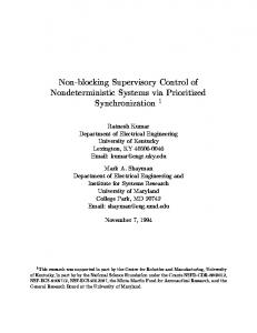
Fig. 1. Single-use camera.
planning modules. The experimental case studies were performed on a PC. Sensor measure samples were acquired from a fixed vision system position and a fixed used product position. The measure is an area, in pixels, of a targeted object in the image. Sensor measures were collected up to 50 samples while maintaining the running average and standard deviation. Disassembly performance was measured in terms of nonvalue-added operations (tool changes and orientation changes), throughput (disassembly time), and capacity (resource utilization). The time to goal not only reflects the efficiency in which the workcell removes a particular sequence of components, but also demonstrates the controllers ability to minimize the number of components required to reach the goal. Manipulator utilization is based on the total active time for the manipulator. For the given workcell, the manipulator moves the tools and the sensor and reorients the product. Sensor utilization is based solely on the acquisition time of the active sensor measure. Tool utilization combines the total active time for all of the end-effector tools: the gripper, the vacuum tool, and the prying tool. A. Case Study on Single-Use Camera Simulation models for a number of integrated disassembly process scenarios have been developed for a single-use camera as shown in Fig. 1. The camera provides a good example from a material and connectivity perspective. The following analysis on the single-use camera represents three strategies. The first strategy, targeted disassembly (TD), takes maximum advantage
LEE AND BAILEY-VAN KUREN: DISASSEMBLY AUTOMATION WORKCELL BASED ON BLOCKING TOPOLOGY
TABLE I RESOURCE BLOCKING MATRIX
TABLE II SINGLE-USE CAMERA COMPONENTS
of the reusable components (base, view box, subassembly, and cantilever). Thus, only nonreusable components are specified as goal components and the removal operations are nondestructive. The second and third strategies are two different alternatives for recycling where metals are segregated from plastics. In the second strategy, complete disassembly (CD), the used products are completely dismantled while segregating the materials. Thus, all the components are treated as goal components. The third strategy, material segregation (MS), attempts to minimize the number of components to be removed. Hence, only the nonplastic components are treated as goal components. 1) Experimental Setup: The resources and its blocking are summarized in Table I. The single-use camera matrix has 17 components constructed of plastic and metal materials. Table II summarizes the components where * denotes nonplastic components, TN refers the tool number in Table I, DT is the disconnection time in seconds, PO denotes the product orientation, and JP characterizes the jamming probability of the components. In Table II, the value of PO is the rotation in degrees between a defined home orientation and the orientation required disconnecting the component. The jamming probabilities for the snap-fit connections are based on the difficulties encountered in manually disassembly. The components in bold are components in which user tampering is less likely and are potentially reusable. The DT is the total time taken for the series of elemental operations required to disassemble
73
TABLE III PERFORMANCE COMPARISON AMONG STRATEGIES
the component and was determined experimentally using the lowest operating velocity (75 mm/s) of a Cincinnati Milacron T3 robot. This elemental approach is similar to the RTM (robot time and motion) developed by Nof and Lechtman [19]. for the single-use camera The component blocking matrix is presented in (23). The formulation of this matrix corresponds to the rule stated in (6). The matrix is 19 19 to account for the 17 components, the null state, and the subassembly. An example of the matrix entries is as follows. The third column corresponds to the top cover. The only entry of 1 is in the first row. The first row corresponds to the null component. Therefore, no components block the removal of the top cover and it is accessible from the null state.
(23)
The sensor measure for each component is the area of an image object. Component feature data were recorded for increasing sample sizes from 10 to 100. It was found that the mean and standard deviation did not vary significantly for samples of 40 or larger. Each simulation run represents a batch of product processing through the disassembly workcell. Preliminary simulation runs showed little variation in results as the number of runs were increased above 50. A batch size of 50 used products was chosen to provide a significant sample of output data for the test case. The real mean and standard deviation of the output statistics are not known but expected to be normally distributed. 2) Results and Discussions: Table III and Fig. 2 show some of the results obtained. A more detailed discussion can be found in [20]. Fig. 2 shows typical tool changes of the disassembly controlled system as a function of time for the three different
74
IEEE TRANSACTIONS ON ROBOTICS AND AUTOMATION, VOL. 16, NO. 1, FEBRUARY 2000
Fig. 2.
Number of tool changes as a funciton of time.
Fig. 3.
Implementation of the TD strategy using product line approach.
strategies. Each discrete point represents the completion of a component removal. The results indicate that the TD strategy took approximately 12.2 min to reach the goal state, 30% and 50% shorter than the MS and the CD strategies, respectively. The smaller goal set and the fact that the set was located toward the product exterior and required mostly the same tools account for this result. Although the MS strategy has only six goal components, the number of tool changes was higher than that of the CD strategy. Recall that the system optimization is essentially a two-step process. The first step is to satisfy (7) minimizing the number of disconnections. The second step minimizes the cost function given by (16). If the number of goal components is relatively small, (7) tends to yield a unique or smaller set of components to satisfy the first criteria. Since all components are goal components for the CD strategy, the secondary criteria that minimize tool changes is called more often than that of the MS strategy with six goal components. The primary criteria of removing goal components become more prominent for material segregation. The minimization of the cost function may not be considered. Consequently, the number of tool changes for the MS strategy with six components was greater than that of the CD strategy. Due to the component connectivity, 15 components must be removed to acquire the goal in the MS strategy. The simulation was repeated with the 15 components removed specified as goal components. Table III shows that the number of goal component changes did not result in a significant difference in time-to-goal
in the MS strategy. In fact, the difference in the time associated with tool changes between the best and the worst cases for the same number of orientation changes and components removed is less than 5%. The primary reason is that the tool change time is relatively small in comparison to that of the disconnection motion time for the flexible workcell. When the disassembly is implemented in a production line approach where modular stations are arranged in sequence, the number of tool changes to achieve the goal product state has a direct effect on the system layout. Fig. 3 shows the disassembly sequence (2; 5, 6, 7; 3; 12, 13, 14 15; 4; 17) that resulted from the TD strategy implemented using the production line approach, where the numbers refer to the component numbers in Table II. The semicolons in the disassembly sequence segregate the components for the six sequential workstations based on the type of tool needed for removal. From Table II, the task operation time for each station can be determined. For example, component 2 can be removed with tool 5 in 66 s, whereas the time required for sequential removal of components 5, 6, and 7 with tool 4 is 122 s, nearly twice the time as compared to that of the first station. Similarly, the times required by stations 3, 4, 5, and 6 are determined to be 54, 176, 63, and 41 s, respectively. Fig. 3 shows an example production line for implementing such a disassembly sequence. The ten modular stations are required to achieve a throughput of 40 units/h operated at an average machine utilization of 84%. For the same throughput, the MS and the CD strategies would require 13 and 16 stations at an average machine utilization of 81% and 77%, respectively.
LEE AND BAILEY-VAN KUREN: DISASSEMBLY AUTOMATION WORKCELL BASED ON BLOCKING TOPOLOGY
75
TABLE IV VARIATION IN SENSOR MEASURE DUE TO SAMPLE SIZE
Fig. 4.
Images and measure distribution for a PC card battery.
B. Case Study Example 2: PC To show the performance of the disassembly error handling strategies, a disassembly simulation was constructed in C based on a PC. The computer contains a lithium battery on one circuit card, which was treated as a goal component. It is of interest to remove the goal component nondestructively since the battery is treated here as a hazardous material to prevent material contamination. Table IV presents the mean and standard deviation of battery images at ten sample intervals. The mean and standard deviation stabilized starting around 40 samples and thus a sample size of 50 was used for subsequent sensor measures. Example images for a circuit card battery from a PC and the resultant distribution parameters are presented in Fig. 4. The object measured in the first image is the large circular object near the image center. Once the battery is removed, a metal strip shows up in the second image, which becomes the measured image object for the second distribution. The corresponding tolerance limits for the circuit card battery were determined at sample size for a population proportion of 0.99, and a degree of equal to 3.385. The battery is conconfidence of 0.99 with Fursidered to exist for sensor measures between thermore, the battery is considered missing for sensor measures These distributions correspond to the feature within measures presented in (20) and (21) and are utilized to map component states. Time and sensing data were collected for disassembly operations of the individual components of a PC. The example product was limited to 20 of its components that represented necessary and unnecessary components for removal of the goal component. These components are shown in Fig. 5. Robot movements linking individual disassembly sequences were estimated based on known positions in the robot work envelope and real robot velocities. PC disassembly was simulated for eight scenarios (see Table V) testing the effects of various component uncertainties
Fig. 5.
PC schematics.
upon the goal of removing the lithium battery. Cases A, B, and C verify the effectiveness of the component existence routine as presented in (21). Cases D and E test the jammed component recovery algorithm. Cases F and G test the replacement component recovery algorithm. A key measure of disassembly efficiency is the ratio of nongoal-to-goal components removed. Some set of components is necessary to remove in order to disassemble the goal components, based on the product design. Therefore, the design determines the minimum ratio that can be achieved. If the disassembly system fails to remove the goal component, the ratio is infinity. Simulation results are presented in Table V. Performance is compared between automated disassembly with and without error handling capability. In general, the error handling control decreases nonvalue-added operations while increasing throughput with little change to system utilization. In terms of goal component acquisition, the error handling control averages component removal ratios of 7.2 as compared to 15.67 for no error handling. This average does not include infinite ratios. The product design requires a component ratio of 8 if no components are missing. The real product in case B has a minimum ratio of 2. The real products in cases C and D have a minimum ratio of infinity. Error handling reduces the number of infinity ratios from 4 to 2. As indicated in Table V, the error handling routine results in a reduction in average disassembly time from 10.02 to 8.33 min. Some of this reduction in time results from a reduction in nonvalue-added operations from 8.46 to 7.43. These gains in performance can be attributed to the ability of the error handling routine to avoid removing components that are not necessary to reach the goal components.
76
IEEE TRANSACTIONS ON ROBOTICS AND AUTOMATION, VOL. 16, NO. 1, FEBRUARY 2000
TABLE V SIMULATION RESULTS FOR PC DISASSEMBLY
VII. CONCLUSIONS A model for automated disassembly was developed that describes the used product and workcell states. Based on the concept of blocking topology, the model accounts for workcell interaction and used product constraints. It was shown that the next component for disassembly can be selected from the knowledge of the product design and the current component for disassembly, thus minimizing the steps to goal component removal. The selection of a component from a set of components for removal was determined by the minimum setup time for disassembling a component. A method for utilizing sensor feedback to detect differences from the expected design configuration was presented. Simulation results based on real product and process input showed that the model could be used under different disassembly strategies to provide performance measures of the disassembly process. Furthermore, simulation results can be extended to provide disassembly line proposals based on a disassembly strategy. An error handling strategy for automated disassembly of a used product has been introduced. Elements of this strategy included designing a sensing strategy, translating feedback into errors, and applying error recovery routines. A statistically based sensor strategy design constraint was established. The constraint can be used to determine if a sensor is appropriate for a given component. To utilize the sensor information, an error detection logic was presented, utilizing sensor measure tolerance limits and workcell states. The error detection logic is required to initiate the error handling routines. Replacement component errors can be accounted for with replacement component families to intelligently provide a reduced search. Jammed component errors are handled with a search for alternate disassembly sequences. This search can be easily implemented through an update of the used products blocking matrix. The benefits of the error handling capability were displayed through simulated
results of a PC. The disassembly simulation shows results for a single sensing strategy with error handling capability. Future work will extend the use of the disassembly simulation to compare sensor strategies for a given product and to compare design changes with a given sensor strategy. ACKNOWLEDGMENT The authors wouldlike to thank the anonymous reviewer for his or her valuable suggestions. REFERENCES [1] D. Navin-Chandra, “Design for environmentability,” in Third Int. Conf. Design Theory and Methodology, American Society of Mechanical Engineers, Miami, FL, 1991, pp. 119–125. [2] D. S. Burke, K. Beiter, and K. Ishii, “Life-cycle design for recyclability,” in Fourth Int. Conf. Design Theory and Methodology, American Society of Mechanical Engineers, Miami, FL, 1992, pp. 325–332. [3] S. Ashley, “Designing for the environment,” Mech. Eng., vol. 115, no. 3, pp. 53–55, 1993. [4] F. Jovane et al., “Key issue in product life cycle: Disassembly,” CIRP Annals, vol. 42, no. 2, pp. 651–658, 1993. [5] J. Scheuring, B. Bras, and K.-M. Lee, “Significance of design for disassembly in integrated disassembly and assembly processes,” Int. Journal of Environmentally Conscious Design & Manufacturing, vol. 3, no. 2, pp. 21–33, 1994. [6] T. L. DeFazio and D. E. Whitney, “Simplified generation of all mechanical assembly sequences,” IEEE Trans. Robot. Automat., vol. RA-3, pp. 640–658, Dec. 1987. [7] L. S. Homem de Mello and A. C. Sanderson, “A correct and complete algorithm for the generation of mechanical assembly sequences,” IEEE Trans. Robot. Automat., vol. 7, pp. 228–240, Apr. 1991. [8] A. Weigi, “Requirements for robots assisted disassembly of not appropriately designed electronic products: Lessons from first studies,” in Proc. 1994 IEEE Int. Symp. Electron. Environment, 1994, pp. 337–342. [9] P. Dario and M. Rucci, “Approach to disassembly problems in robotics,” in 1993 Int. Conf. Intell. Robot. Syst., 1993, pp. 460–467. [10] D. Spath, “Utilization of hypermedia-based information systems for developing recyclable products and for disassembly planning,” CIRP Annals, vol. 43, no. 1, pp. 153–156, 1994. [11] B. Schmult, “Autonomous robotic disassembly in the blocks world,” Int. J. Robotics Res., vol. 11, no. 5, pp. 437–458, Oct. 1992.
LEE AND BAILEY-VAN KUREN: DISASSEMBLY AUTOMATION WORKCELL BASED ON BLOCKING TOPOLOGY
[12] J. S. Albus, “Hierarchical interaction between sensory processing and world modeling in intelligent systems,” in Proc. 5th IEEE Int. Symp. Intell. Control, 1990, pp. 53–59. [13] A. Saleh, N. G. Odrey, and G. R. Wilson, “Design and algorithmic implementation of a real–time controller for a manufacuring cell,” in Des. Anal. Contr. Manufacturing Cells. New York: Amer. Soc. of Mech. Eng., vol. 53, pp. 205–229. [14] J. R. Munkres, Analysis on Manifolds. Redwood City, CA: AddisonWesley, 1991, pp. 25–31. [15] M. Kline, Mathematical Thought from Ancient to Modern Times. New York: Oxford Univ. Press, vol. 3, pp. 1160–1161. [16] A. E. Samuel, P. R. McAree, and K. H. Hunt, “Unifying screw geometry and matrix transformations,” Int. J. Robot. Res., vol. 10, no. 5, pp. 454–472, Oct. 1991. [17] B. Paden and S. Sastry, “Optimal kinematic design of 6R manipulators,” Int. J. Robot. Res., vol. 7, no. 2, pp. 43–61, Mar./Apr. 1988. [18] K.-M. Lee and Y. Qian, “Intelligent vision-based part-feeding on dynamic pursuit of moving objects,” in Proc. SPIE’s Symp. Photoics East, Philadelphia, PA, Oct. 23–26, 1995, pp. 172–183. [19] S. Y. Nof and H. Lechtman, “The RTM method of analyzing robot work,” Ind. Eng., pp. 38–48, Apr. 1982. [20] M. M. Bailey-Van Kuren, “Automated Cell Supervisory Control for Product Disassembly,” Ph.D. dissertation, Georgia Institute of Technology, Atlanta, 1996.
77
Kok-Meng Lee (M’89) received the B.S. degree in mechanical engineering from the State University of New York at Buffalo in 1980 and the S.M. and Ph.D. degrees in mechanical engineering from the Massachusetts Institute of Technology, Cambridge, in 1982 and 1985, respectively. He is a Woodruff Associate Professor at the George W. Woodruff School of Mechanical Engineering, Georgia Institute of Technology, Atlanta. His research interests include system dynamics and control, robotics, automation, and optomechatronics. He holds five patents in machine vision, three degree-of-freedom variable reluctance spherical motor, and optical orientation encoder. Dr. Lee is a senior member of SME. He has been an active member of the ASME Dynamic System and Control Division and the IEEE Robotics and Automation Society. He has served as an Associate Editor for the IEEE TRANSACTIONS ON ROBOTICS AND AUTOMATION and the IEEE Robotics and Automation Magazine, as well as an Editor for the IEEE/ASME TRANSACTIONS ON MECHATRONICS. He served as a General Chair for the 1999 IEEE/ASME International Conference on Advanced Intelligent Mechatronics. He received the National Science Foundation (NSF) Presidential Young Investigator Award, Sigma Xi Junior Faculty Research Award, and International Hall Of Fame New Technology Award.
Michael Bailey-Van Kuren received the B.S. degree in industrial engineering from Purdue University, West Lafayette, IN, in 1988, the M.S. degree in mechanical engineering from the University of California at Santa Barbara in 1993, and the Ph.D. degree in mechanical engineering from the Georgia Institute of Technology, Atlanta, in 1996. In 1998, he joined Miami University, Oxford, OH, as an Assistant Professor of Manufacturing Engineering. His current research interests include robotic systems, demanufacturing, modular automation, and manufacturing controls.