PAS-102, pp. 2420â2429,. Aug. 1983. .... the Electromagnetic Compatibility (EMC) group of the Swiss Federal Institute ... groups dealing with lightning and EMC.
IEEE TRANSACTIONS ON POWER DELIVERY, VOL. 19, NO. 1, JANUARY 2004
423
Mitigation of Lightning-Induced Overvoltages in Medium Voltage Distribution Lines by Means of Periodical Grounding of Shielding Wires and of Surge Arresters: Modeling and Experimental Validation Mario Paolone, Carlo Alberto Nucci, Senior Member, IEEE, Emanuel Petrache, and Farhad Rachidi, Senior Member, IEEE
Per-unit-length inductance matrix of the line. Per-unit-length capacitance matrix of the line. Vector of the horizontal component of the exciting (or incident) electric field along the axis at the th conductor’s height . Vector of the exiting (or incident) voltage, due to the exciting (or incident), vertical component of the electric field.1 Vector of the line currents. Vector of the currents flowing through the grounding connections. Vector of the scattered voltage. Vector of the total voltage. Matrix of the integro-differential operators describing the voltage drop across the grounding connection as a function of current . Vector of the vertical component of the exciting (or inducing) electric field.
Abstract—In this paper, we investigate the effect of periodically-grounded shielding wires and surge arresters on the attenuation of lightning-induced voltages. We discuss the adequacy of the commonly made simplification of assuming the shielding wire at ground potential, instead of being treated as one of the conductors of the multiconductor system. We also compare then the mitigation effect of shielding wires with that achievable by the insertion of surge arresters along the line. The computation results are first validated by means of calculations obtained by other authors referring to a simple line configuration, and then by means of experimental results obtained using a reduced-scale line model illuminated by a nuclear electromagnetic pulse (NEMP) simulator. One of the main conclusions is that the effectiveness of shielding wires and surge arresters depends mostly on the spacing between two adjacent grounding points or surge arresters. Index Terms—Grounding, lightning-induced voltages, shielding wire, surge arrester.
NOMENCLATURE Height of conductor . Height of shielding wire. Grounding resistance of the shielding wire footing. Lightning-induced voltage amplitude on th conductor in absence of shielding wire, as predicted by the Rusck formula. Lightning-induced voltage amplitude on th conductor in presence of shielding wire, as predicted by the Rusck formula. Surge impedance of the shielding wire. Mutual surge impedance between shielding wire and th conductor. Spatial integration step in the first-order pointcentered finite-difference time-domain integration scheme. Time integration step in the first-order pointcentered finite-difference time-domain integration scheme. Manuscript received September 17, 2002. M. Paolone and C. A. Nucci are with the University of Bologna, Bologna 40136, Italy. E. Petrache and F. Rachidi are with the Swiss Federal Institute of Technology, Lausanne 1015, Switzerland. Digital Object Identifier 10.1109/TPWRD.2003.820196
I. INTRODUCTION
L
IGHTNING-INDUCED voltages are nowadays a major issue in electromagnetic compatibility and power-quality domains. The need for a good quality in the power supply along with the widespread use of sensitive devices connected to distribution lines makes the protection against lightning-induced disturbances of primary importance. Concerning medium voltage overhead lines, the main protective measures against short interruptions and voltage sags originated by lightning-induced voltages can be identified as i) use of shielding wires and/or ii) use of surge arresters, iii) increasing of the line insulation level. In this paper, we shall focus on points i) and ii). Regarding the first point, several authors have addressed theoretically the issue by assuming the shielding wire at zero potential at any point of it and at any time [1]–[6]. Such an assumption appears reasonable only when the shielding wire is grounded at short intervals along the line. Further, such an approach does not allow to find the “optimal” distance between two adjacent groundings which would result in the required shielding effect. 1Where subscript i denotes the particular wire of the multiwire line consisting in phase and shielding wire conductors;
0885-8977/04$20.00 © 2004 IEEE
424
IEEE TRANSACTIONS ON POWER DELIVERY, VOL. 19, NO. 1, JANUARY 2004
In [7], an improved approach was used in which the shielding wire was considered as one of the conductors of the multiconductor line. The coupling model adopted was the same proposed by Rusck [1] which has been shown to apply for the case of a lightning channel perpendicular to the ground plane. In [8] and [9], the coupling between the LEMP and the multiconductor transmission line was described by the more general coupling model of Agrawal et al. [10] in which the shielding wire was treated, similarly to [7], as one of the conductors of the multiconductor line. In particular, in [8] and [9], the shielding wire was grounded only at the line terminations. In this paper, we extend and generalize the model already presented in [8] and [9] by allowing for the treatment of the line transverse discontinuities represented by the vertical connections between the line conductors and the ground. These connections are constituted by the groundings of the shielding wire and by the surge arresters connected between the phase conductors and the ground. We first compare our results with those obtained by Yokoyama in [7] that refer to a simple configuration. We then test the extended model by means of experimental data obtained using a reduced-scale line model illuminated by an EMP simulator. We finally assess the effect of both shielding wires and surge arresters on voltages induced by a nearby cloud-to-ground lightning by performing a sensitivity analysis. II. TREATMENT OF AN OVERHEAD LINE WITH PERIODICALLY-GROUNDED SHIELDING WIRES ILLUMINATED BY AN EXTERNAL ELECTROMAGNETIC FIELD A. Extension of the Agrawal et al. Coupling Model to the Case of a Multiconductor Line With Periodically-Grounded Shielding Wire In general, field-to-transmission line coupling models have been developed for the case of uniform transmission lines (e.g., [10]). The presence of transverse discontinuities along the line, such as those due to periodical grounding of the shielding wire, needs to be properly treated in the resolution algorithm. For a homogeneous lossless multiconductor line along the -axis2 above a perfectly conducting ground and illuminated by an external field, the Agrawal et al. coupling equations are (see nomenclature for the definition of used symbols) (1) (2) The vector of the scattered voltage is related to the total voltage vector by the following expression:
(3) overhead line is assumed to be oriented along the x-axis of a (x, y , z ) Cartesian coordinate system, above the x, y ground plane. 2The
These equations have been solved in [8] by means of the point-centered finite difference technique in time domain (FDTD). According to the extension of the Agrawal model that we propose (see the Appendix for details), the scattered voltage, at the node at which a shunt admittance (linear or nonlinear) is connected to ground, can be expressed as follows:
(4)
where the symbols are defined in the nomenclature. The operator could, for instance, represent the pole footing impedance, for which models are already available (e.g., [11]). In our study, due to the frequency content of lightning-induced voltages (below 10 MHz), we shall assume in a first approximation that the pole footing impedance can be approximated . Additionally, due to the by a lumped constant resistance relatively low value of the induced current, soil ionization phenomena will be disregarded. The Agrawal model being expressed in terms of the scattered voltage, it is necessary to include a voltage source in series with the transverse impedance, the so-called exciting (or incident) voltage, which is given by the integral from the ground level to the line conductor, of the exciting vertical electric field (see Fig. A.1 of the Appendix). For the case of a lossy ground, the equations for the extended model are modified by introducing in the left-hand term of (1) a convolution product between the time-derivative of the line current and the so-called ground transient resistance of the line [8], [9], while, in the right-hand term, the horizontal electric field expression is calculated according to the Cooray–Rubinstein formula [12], [13]. B. Validation of the Proposed Model The validation of the proposed extension of the Agrawal coupling model, modified to take into account the presence of transverse discontinuities, is first performed by testing it with the theoretical results of Yokoyama, published in [7].3 The line configuration considered in [7] is shown in Fig. 1: note that only one grounding of the shielding wire, located at the line center and in front of the stroke location, is considered. The computation results by Yokoyama are presented in Fig. 2(a); ours are shown in Fig. 2(b) and, clearly, refer to the same values of grounding resistance adopted in [7]. As it can be seen by the figures, the agreement is very good. The results of Fig. 2 show also that the value of the grounding resistance largely affects the amplitude of the induced voltages. The reason for such a result can be ascribed, as we shall see better in what follows, to the fact that the considered stroke location is situated just in front of the grounding resistance. Note that the illuminated-line model considered in [7] refers to the case of an overhead line above an ideal ground. This is, to a certain extent, in contradiction with the fact of considering a resistance of the shielding wire groundings different from zero. 3It is worth noting that Yokoyama [7] used the model by Rusck [1], which is equivalent to the model by Agrawal when the lightting channel is perpendicular to the ground plane [14].
PAOLONE et al.: MITIGATION OF LIGHTNING-INDUCED OVERVOLTAGES IN MEDIUM VOLTAGE DISTRIBUTION LINES
1000m
100m
0.8cm
425
Shielding wire grounded at line center Phase conductors
Matched
Rg
Matched
10m
0.5m 0.5m
2 km
Fig. 1. Line geometry to evaluate the effect of a shielding wire on lightning-induced overvoltages. Lightning current trapezoidal waveshape: maximum amplitude 100 kA; steepness of the linear rising part 50 kA=�s. Ideal ground. (Same as in [7].)
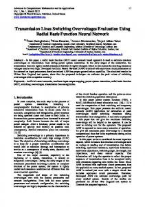
Fig. 3. SEMIRAMIS EMP simulator (a) and the vertical electric field inside its working volume in absence of the line (b). Fig. 2. Induced voltage at the line center on phase conductors for a variable grounding resistance. Line configuration of Fig. 1, same as in Yokoyama [7, Fig. 4], (a) results obtained by Yokoyama [7]; (b) results obtained with the proposed line model.
As a matter of fact, to experimentally test the validation of the Rusck model, Yokoyama set up an ingenious experimental installation where the shielding wire grounding resistance was represented by a lumped resistance soldered to the perfectly conducting ground plane [15]. An experimental validation of our model is also performed by using reduced scale line models illuminated by the EMP simulator of the Swiss Federal Institute of Technology in Lausanne (SEMIRAMIS, for a detailed description of the simulator, see [16]). The simulator is a bounded wave vertically-polarized
type, with a working volume of m [see Fig. 3(a)]. A measurement record of the waveform of the electric vertical field inside the working volume, performed in absence of the line, is presented in Fig. 3(b). The field has a rise time of about 8 ns and a decay time of about 150 ns. Several reduced-scale line models reproducing single and multiconductor line configurations were used for the tests. The procedure used for the validation is based on the measurement of the electric field generated in the simulator in absence of the line [see Fig. 3(b)] and of the induced currents measured at different line terminations of the reduced-scale line models. The measured incident field is input to the modified Agrawal model computer code and the computed induced currents are compared with measured waveforms.
426
IEEE TRANSACTIONS ON POWER DELIVERY, VOL. 19, NO. 1, JANUARY 2004
Fig. 4. Reduced-scale line model composed by a single-conductor and a shielding wire grounded at the line extremities, used for the experiment carried out with the SEMIRAMIS EMP simulator.
Fig. 5. Reduced-scale line model composed by three conductors and a shielding wire grounded at the line extremities, used for the experiment carried out with the SEMIRAMIS EMP simulator.
In what follows, we report the results concerning both a single-conductor configuration with a shielding wire grounded at the line extremities (Fig. 4), and a vertically-disposed three-conductor configuration with a shielding wire grounded at line extremities and at the line center (Fig. 5). For the configuration with a single-conductor, the shielding wire was placed successively above and under the phase conductor at two different heights, namely 18 or 22 cm (as shown in Fig. 4). Fig. 6 shows, for the single-conductor configuration, a comparison between measurements and simulations, relevant to the current at line terminations in the phase conductor with and without the presence of the shielding wire. It can be seen that the numerical results agree well with the experimental data. In addition, as expected, the shielding wire is more efficient in mitigating the induced voltages when it is placed above the phase conductor. For the three-phase configuration, the shielding wire was placed above the highest phase conductor (as indicated in Fig. 5). Fig. 7(a) shows a comparison between measured and simulated current in the middle line conductor, with and without the presence of the shielding wire; Fig. 7(b) shows a comparison between measurements and simulations relevant to the induced current in the shielding wire. Again, it can be seen that the numerical simulations are in excellent agreement with measurements. III. ANALYSIS OF THE EFFECT OF SHIELDING WIRES ON LIGHTNING-INDUCED VOLTAGES To better assess the effect of the shielding wire, of the distance between two consecutive groundings and of the value of the grounding resistance on the amplitude of the induced voltages, we have considered the line geometry shown in Fig. 8 in which the stroke location does not “face” any of the grounding points. The computed peak amplitudes of the induced voltages along the line are presented in Fig. 9 for the case of a perfectly-con-
Fig. 6. Comparison between experimental results and simulations relevant to the line configuration of Fig. 4. Current induced in the phase conductor; (a) height of shielding wire: 18 cm; (b) height of shielding wire: 22 cm.
ducting ground. In the same figure, we also present the results obtained using the Rusck formula given by [1]
(5) where the symbols are defined in the nomenclature. It is worth reminding that the Rusck expression does not cover the case of multiple groundings of the shielding wire (it assumes that the shielding wire is at ground potential) and, furthermore, it assumes the ground as perfectly conducting. In Fig. 9, we can see that an overall effective protection of the line can be achieved only if the spacing between two consecutive groundings is less than about 200 m. This value approximately corresponds to the risetime of the lightning electromagnetic field illuminating the line, for the assumed lightning current waveshape. For larger values of spacing (namely 500 and 1000 m), only the portion of the line in the immediate vicinity of the grounding points appears to be protected. From Fig. 9, one can also see that the Rusck simplified formula gives quite accurate results for short spacings between two
Maximum Amplitude of Induced Overvoltage [kV]
PAOLONE et al.: MITIGATION OF LIGHTNING-INDUCED OVERVOLTAGES IN MEDIUM VOLTAGE DISTRIBUTION LINES
3.5 measurement: phase conductor #2 without SW simulation: phase conductor #2 without SW measurement: phase conductor #2 with SW simulation: phase conductor #2 with SW
3
Current [A]
2.5 2 1.5 1 0.5 0 -0.5 0
a)
0.05
0.1
0.15
0.2
Time [µs] 14
measurement: conductor SW simulation: conductor SW
Current [A]
Rg = 0 Ω 200
150
100 without shielding wire ∆g = 1000 m ∆g = 500 m ∆g = 200 m ∆g = 100 m Rusck
50
0 0
200
400
600
800
1000
Fig. 9. Maximum amplitude of the induced voltage along the line as a function between two adjacent groundings of the shielding wire. of the spacing Line configuration of Fig. 8, stroke location 50 m from the line and 370 m from left line termination. Perfectly conducting ground. Lightning current: maximum =� . amplitude 30-kA maximum time derivative 100
(1g)
kA s
10 8 6 4 2 0 -2
b)
0
0.05
0.1
0.15
0.2
Time [µs]
Fig. 7. Comparison between experimental results and simulations relevant to the line configuration of Fig. 6. (a) current induced on line conductor #2 (middle phase conductor); (b) current induced on the shielding wire. Stroke Location
Phase conductor Rg
Rg
Shielding Wire
Zc
Rg
1 cm
10m
50m
Rg
Variable
9m
370m
Zc
250
Position of Observation Point Along the Line [m]
12
Rg
427
1 km
Fig. 8. Configuration adopted to evaluate the mitigation effect of shielding wires on lightning-induced voltages. Lightning current: maximum amplitude 30-kA maximum time derivative 100 =� .
kA s
adjacent groundings (less than 200 m) and when assuming a perfectly conducting ground. Fig. 10(a) and (b) present similar computed results as those presented in Fig. 9, but considering a finite value for the ground conductivity equal to 0.001 S/m. In Fig. 10(a), we adopt the value of 10 for the grounding resistance, while in Fig. 10(b) the value of 300 was adopted. These values correspond to two different dimensions of the grounding electrodes. The results presented in Fig. 10(a) and (b) show clearly that the mitigation effect of the shielding wire depends, in general, more on
the spacing between two consecutive groundings rather than on the value of the grounding resistance. This differs from the case of direct stroke for which the effectiveness of the shielding wire depends strongly on the grounding resistance. Additional calculation results show that it is only when the grounding resistance becomes poor (100 or larger), that it starts to affect in a more significant way the distribution of the induced voltage along the line. Note additionally that it is only when the stroke location is located in front of a grounding point that the attenuation of the induced voltage on the phase conductors is very dependent on the value of the grounding resistance. To better comprehend the above obtained results, we show in Fig. 11(a) and (b) the induced voltages along the shielding wire relevant to the line geometry of Fig. 8, considering a lossy , a grounding resistance ground with , and considering two different grounding spacing equal to 500 m [Fig. 11(a)] and 100 m [Fig. 11(b)], respectively. In Fig. 11(a), we can see that the voltage along the shielding wire varies significantly as a function of time and position along the wire. In such a case, the assumption of considering the shielding wire as a zero-potential conductor is not realistic. On the other hand, the variation of the shielding wire voltage for 100-m spacing [Fig. 11(b)] is less important, justifying therefore, for such a case, the use of the Rusck formula to evaluate the mitigation effect of a shielding wire. IV. TREATMENT OF AN OVERHEAD LINE WITH SURGE ARRESTERS The presence of surge arresters along the line can be treated in a similar way as done for the discontinuities caused by the periodical groundings of the shielding wire (see the Appendix). The surge arrester is represented by a nonlinear V–I characteristic element placed in series with the incident voltage source (Fig. A.1). The V-I characteristic of the surge arrester is shown in Fig. 12.
IEEE TRANSACTIONS ON POWER DELIVERY, VOL. 19, NO. 1, JANUARY 2004
Time [us]
8
200 150
125 kV
6
60 kV 4
100
2
50
0
-5 kV -70 kV -135 kV 200
0
0
without shielding wire ∆g = 1000 m ∆ g = 500 m ∆ g = 200 m ∆g = 100 m
-50
400
600
800
1000
b)
320 kV
10
255 kV 8
-100 0
200
400
-200 kV
Position of Observation Point Along the Line [m]
600
800
1000
Position of Observation Point Along the Line [m]
190 kV 125 kV
6
60 kV 4
-5 kV
2
-70 kV
300 Rg= 300 Ω
250
-135 kV 0 200
0
200
400
600
800
1000
-200 kV
Position of Observation Point Along the Line [m] 150
Fig. 11. Total voltage of the shielding wire conductor relevant to the line geometry of Fig. 8, for a lossy ground with � : S/m, and grounding . (a) Spacing between two adjacent groundings of the resistance R m. (b) Spacing between two adjacent groundings of shielding wire the shielding wire g m.
= 0 001
= 10
1g = 500 1 = 100
100 50 0
without shielding wire ∆ g = 1000 m ∆ g = 500 m ∆ g = 200 m ∆ g = 100 m
-50
100
-100 0
200
400
600
800
1000
Position of Observation Point Along the Line [m]
Fig. 10. Maximum amplitude of the induced voltage along the line as a between two adjacent groundings of the shielding function of the spacing wire. Line configuration of Fig. 8, stroke location 50 m from the line and 370 m from left line termination. Lossy ground � : S/m. Lightning current: maximum amplitude 30-kA maximum time derivative 100 =� . (a) Grounding resistance equal to 10 . (b) Grounding resistance equal to 300 .
(1g)
190 kV
= 0 001
kA s
1 1.0E-07
1.0E-05
1.0E-03
Current [A]
20820 25980 29100 31140 33300 47460 51000 56640
0.09E-02 0.12E-02 0.06E-01 0.06 0.6 3000 6000 12000
1.0E-01
1.0E+01
1.0E+03
Current [kA]
Fig. 12.
Surge arrester V–I characteristic. 370m
Stroke Location 50m
To compare the mitigation effect of surge arresters with that of the shielding wire, we have considered the same single-conductor line configuration (see Fig. 13). This means that for this case, we assume that the differential-mode coupling among the line phases is negligible and that the common-mode voltage induced on the three phases is the same. This is certainly a more reasonable assumption for the case of a line illuminated by a lightning electromagnetic field (the illumination is basically the same for the three conductors), than for a line directly struck by lightning (the lightning current in this case can be injected on one conductor of the transmission line). We have considered a variable number of surge arresters placed along the line: two (at the line terminal only), three (every 1000 m), five (every 500 m), and 11 (every 200 m). The amplitude of the induced overvoltages along the line are shown in Figs. 14 (perfectly-conducting ground) and 15 (lossy ground).
Voltage [V]
10
Zc Surge Arrester
1 cm
Variable
Phase conductor Surge Arrester
Surge Arrester
Zc Surge Arrester
Surge Arrester
9m
b)
255 kV
Rg = 10 Ω
250
320 kV
10
Time [us]
Maximum Amplitude of Induced Overvoltage [kV]
a)
a)
300
Voltage [kV]
Maximum Amplitude of Induced Overvoltage [kV]
428
1 km
Fig. 13. Configuration adopted to evaluate the mitigation effect of surge arresters on lightning-induced voltages. Lightning current: maximum amplitude 30-kA maximum time derivative 100 kA/ms.
The computed results show that an important reduction of the induced overvoltages can be achieved only with a large number of surge arresters namely one surge arrester every 200 m. It can
Maximum Amplitude of Induced Overvoltage [kV]
PAOLONE et al.: MITIGATION OF LIGHTNING-INDUCED OVERVOLTAGES IN MEDIUM VOLTAGE DISTRIBUTION LINES
240
of the threshold voltage of the surge arrester’s nonlinear V–I characteristic (see Fig. 12).
160
V. CONCLUSION
80 0 -80 -160 without surge arreser ∆g =1000 m ∆g = 500 m ∆g = 200 m ∆g = 100 m
-240 -320 0
200
400
600
800
1000
Position of Observation Point Along the Line [m]
Fig. 14. Maximum amplitude of the induced voltage along the line as a . Line function of the spacing between two adjacent surge arresters configuration of Fig. 12, stroke location 50 m from the line and 370 m from left line termination. Perfectly conducting ground. Lightning current: maximum amplitude 30-kA maximum time derivative 100 kA=� .
(1sa)
s
Maximum Amplitude of Induced Overvoltage [kV]
429
400 without surge arresters ∆g = 1000 m ∆g = 500 m ∆g = 200 m ∆g = 100 m
300
200
100
0
-100 0
200
400
600
800
1000
Position of Observation Point Along the Line [m] Fig. 15. Maximum amplitude of the induced voltage along the line as a . Line function of the spacing between two adjacent surge arresters configuration of Fig. 12, stroke location 50 m from the line and 370 m from left : S/m. Lightning current: maximum line termination. Lossy ground � amplitude 30-kA maximum time derivative 100 =� .
= 0 001
(1sa)
kA s
also be seen that for some configurations with a low number of surge arresters (e.g., one for each 1000 m), their presence could result in important negative peaks of the induced voltage, which are due to surge reflections occurring in correspondence of surge arresters operation. Indeed, depending on the line configuration, stroke location, and on the distance between two consecutive surge arresters, the negative voltage wave due to the arrester’s nonlinear characteristic, make it possible for the largest amplitude of the induced overvoltage to occur at a point on the line different from that closest to the stroke location. In addition, this overvoltage can be more severe than the maximum voltage amplitude induced in the absence of surge arresters (see Fig. 14). By increasing the number of surge arresters, the maximum amplitude of the induced overvoltage tends to be confined within the range defined by the positive and negative values
In this study, we have extended a model for the calculation of lightning-induced voltages on uniform lines, to take into account the presence of line transverse discontinuities, such as those caused by periodically-grounded shielding wires and by surge arresters. The extended model has been tested and validated versus experimental data obtained using a reduced-scale line model illuminated by an EMP simulator. The proposed model can be used to evaluate the lightning performance of distribution lines equipped with shielding wires and/or surge arresters taking into account the finite ground conductivity in the calculation of the lightning-induced overvoltages. We have shown that the effectiveness of shielding wires and surge arresters depends mostly on the spacing between two adjacent grounding points or surge arresters. The results obtained with the proposed model have also been compared with those predicted by the Rusck simplified formula. It has been shown that the Rusck formula allows for an accurate prediction of the mitigation effect of the shielding wire only when the number of groundings is large, in agreement with the Rusck assumption of considering the shielding wire at zero potential. The proposed method, in comparison with the Rusck formula [1] and with other previously proposed methods [1]–[6], allows one to evaluate the induced overvoltages on overhead lines above a lossy ground taking into account the periodical groundings of shielding wires and the value of the grounding resistance. The simulation results revealed additionally a shortcoming of the effectiveness of surge arresters when they are separated by large distances (e.g., one surge arrester every 1 km). The developed model and relevant computer code can find a useful application in the design and coordination of the considered protection means against lightning-induced voltages. APPENDIX INCLUSION OF TRANSVERSE LINE DISCONTINUITIES IN A POINT-CENTERED FINITE DIFFERENCE TIME-DOMAIN SCHEME OF FIELD-TO-TRANSMISSION LINE COUPLING EQUATIONS The spatial point-centered finite-difference time-domain (FDTD) integration scheme for a single-conductor line illuminated by an external electromagnetic field, around a transverse discontinuity point is illustrated in Fig. A.1. The treatment of such a discontinuity, located anywhere along the line, involves a modification of the numerical solution of the Agrawal model. A. Case of Single-Conductor Lines In the numerical discretization of the Agrawal single-conductor coupling equations [10], [17], the equation that allows to extract a generic node current at time step , is given by (A.1)
430
IEEE TRANSACTIONS ON POWER DELIVERY, VOL. 19, NO. 1, JANUARY 2004
∆x n ik-1
vk
n
ik
∆ x/2
n
Voltage FDTD node Current FDTD node
n ik+1
v k+1n ik ,n
ik ,,n
Γ
ig
vk+ 2
n
k spatial discretization index n time discretization index
∆ x spatial discretization
n
n ik+2
Known quantities: • scattered voltages and currents at time step n except vk+1n, ik n and ik+1n • Vertical Electric Field E z • Line Height h • Operator Γ
discontinuity at one of the conductors of the bundle as a discontinuity of all conductors, in that the conductors, which are not connected to ground, are considered grounded through an infinite resistance. We can then rewrite (A.2), (A.3), and (A.8) for a multiconductor line as follows:
h
∫ Ez ( x, z, t )dz
0
(A.9)
Unknown quantities: n • vk+1 • i n k n • i k+1
Fig. A.1. Insertion of a transverse discontinuity in the FDTD representation of a single-conductor line illuminated by an external electromagnetic field.
(A.10)
where is the line scattered voltage at time step and spatial node ; is the line current at time step and spa; is the horizontal electric field; and , tial node are constants depending on the line inductance , , . (as illustrated in If we write (A.1) for nodes and Fig. A.1), we obtain two FDTD iterative solutions
(A.11) where
(A.2) (A.3) To obtain the third equation (needed for the treatment of transverse discontinuities), we apply the Kirchhoff current equation, at the grounding node, for currents , , and (A.4) Currents and can be expressed as a function of the adjacent current node assuming the following linear spatial interpolation: (A.5) (A.6) Additionally, the scattered voltage for a single-conductor line, as follows:
can be expressed,
(A.7) By introducing (A.4), (A.5), and (A.6) in (A.7), we obtain third solution system equation and matrix
(A.8) B. Case of Multiconductor Lines The treatment of a discontinuity in a multiconductor line is similar to that of the single-conductor line. We will consider a
where
is the number of the line conductors.
PAOLONE et al.: MITIGATION OF LIGHTNING-INDUCED OVERVOLTAGES IN MEDIUM VOLTAGE DISTRIBUTION LINES
ACKNOWLEDGMENT
Mario Paolone was born in Campobasso, Italy, in 1973. He received the M.S. (hons.) and Ph.D. degrees in electrical engineering from the University of Bologna, Italy, in 1998 and 2002, respectively. Currently, he is with the Power Systems Group of the University of Bologna, Bologna, Italy. He is author or coauthor of many scientific papers presented at international conferences. His research interests include power system transients, with particular reference to NEMP and LEMP interaction with electrical networks, power systems dynamics, and electric-ve-
The authors are grateful to M. Dragoni and J. L. Bermudez for their valuable contribution in carrying out the experimental tests. REFERENCES [1] A. Rusck, Induced lightning overvoltages on power transmission lines with special reference to the overvoltage protection of low voltage networks, in Trans. Royal Institute of Technology, Stockholm, Sweden, vol. 120, 1958. [2] P. Chowdhuri and E. T. B. Gross, “Voltages induced on overhead multiconductor lines by lightning strokes,” Proc. Inst. Elect. Eng., vol. 116-4, pp. 561–565, 1969. [3] E. Cinieri and A. Fumi, “Effetto della presenza di più conduttori e di funi di guardia sulle sovratensioni atmosferiche indotte nelle linee elettriche,” l’Energia elettrica, vol. 11–12, 1979. [4] S. Yokoyama, K. Miyake, H. Mitani, and N. Yamazaki, “Advanced observations of lightning induced voltage on power distribution lines,” IEEE Trans. Power Delivery, vol. PWRD-1, pp. 129–139, Apr. 1986. [5] S. Yokoyama, K. Miyake, H. Mitani, and A. Takanishi, “Simultaneous measurement of lightning induced voltages with associated stroke currents,” IEEE Trans. Power App. Syst., vol. PAS-102, pp. 2420–2429, Aug. 1983. [6] P. Chowdhuri, “Lightning-induced voltages on multiconductor overhead lines,” IEEE Trans. Power Delivery, vol. 5, pp. 658–667, Apr. 1990. [7] S. Yokoyama, “Calculation of lightning-induced voltages on overhead multiconductor systems,” IEEE Trans. Power App. Syst., vol. PAS-103, pp. 100–108, Jan. 1984. [8] F. Rachidi, C. A. Nucci, M. Ianoz, and C. Mazzetti, “Response of multiconductor power lines to nearby lightning return stroke electromagnetic fields,” IEEE Trans. Power Delivery, vol. 12, pp. 1404–1411, July 1997. [9] F. Rachidi, C. A. Nucci, and M. Ianoz, “Transient analysis of multiconductor lines above a lossy ground,” IEEE Trans. Power Delivery, vol. 14, pp. 294–302, Jan. 1999. [10] A. K. Agrawal, H. J. Price, and S. Gurbaxani, “Transient response of a multiconductor transmission line excited by a nonuniform electromagnetic field,” IEEE Trans. Electromagn. Compat., vol. EI-22, pp. 119–129, May 1980. [11] IEEE Modeling and Analysis of System Transient Working Group, “Fast front transient task force, modeling guidelines for fast front transients,” IEEE Trans. Power Delivery, vol. 11, pp. 493–506, Jan. 1996. [12] V. Cooray, “Horizontal fields generated by return strokes,” Radio Sci., vol. 27, no. 4, pp. 529–537, 1992. [13] M. Rubinstein, “An approximate formula for the calculation of the horizontal electric field from lightning at close, intermediate, and long range,” IEEE Trans. Electromagn. Compat., vol. 38, pp. 531–535, Aug. 1996. [14] V. Cooray, “Calculating lightning-induced overvoltages in power lines: a comparison of two coupling models,” IEEE Trans. Electromagn. Compat., vol. 36, pp. 179–182, Aug. 1994. [15] S. Yokoyama, K. Yamamoto, and H. Kinoshita, “Analogue simulation of lightning induced voltages and its application for analysis of overhead-ground-wire effects,” Proc. Inst. Elect. Eng., vol. 132, no. C-4, pp. 208–216, 1985. [16] F. Arreghini, M. Ianoz, P. Zweiacker, D. V. Giri, and A. Tehori, “SEMIRAMIS: an asymmetrical bounded wave EMP simulator with a good confinement inside the transmission line,” in Proc. 10th Int. Symp. Electromagn. Compat., Zurich, Switzerland, 1993, pp. 583–588. [17] C. A. Nucci, V. Bardazzi, R. Iorio, A. Mansoldo, and A. Porrino, “A code for the calculation of lightning-induced overvoltages and its interface with the Electromagnetic Transient Program,” in Proc. 22nd Int. Conf. Lightning Protection, Budapest, Hungary, 1994.
431
hicle batteries.
Carlo Alberto Nucci (M’91–SM’02) was born in Bologna, Italy, in 1956. He received the M.S. (hons.) and Ph.D. degrees in electrical engineering from the University of Bologna, Italy, in 1982 and 1986, respectively. Currently, he is Full Professor in power systems at the University of Bologna and was an Associate Professor there in 1992. He was a Researcher with the Power Electrical Engineering Institute at the University of Bologna in 1982. He is author or co-author of many scientific papers published on reviewed journals or presented at international conferences. His research interests include power systems transients and dynamics, with particular reference to lightning and nuclear EMP impact on power lines, voltage collapse, power station simulators, and the study of power components including medium voltage capacitors and traction batteries. Dr. Nucci was the Chairman of the IEEE Bologna Power Tech in June 2003 and is the Chair of the IEEE Central and South Italy/North Italy Joint Power Engineering Society Chapter–PE31. He is a member of the IEEE Working Group “Lightning performance of Distribution lines,” of the CIGRE Working groups 33.01 “Lightning” (of which he is also secretary) and 36.07 “Power quality indices and objectives.”
Emanuel Petrache was born in Constanta, Romania, in 1975. He received the M.S. degree in electrical engineering from the University Politehnica, Bucharest, Romania, in 1998. He is currently pursuing the Ph.D. degree within the Electromagnetic Compatibility (EMC) group of the Swiss Federal Institute of Technology, Lausanne, Switzerland. His research interests include numerical computation of electromagnetic fields, lightning, and EMP interaction with transmission lines.
Farhad Rachidi (M’93–SM’02) was born in Geneva, Switzerland, in 1962. He received the M.S. degree in electrical engineering and the Ph.D. degree from the Swiss Federal Institute of Technology, Lausanne, Switzerland, in 1986 and 1991, respectively. Currently, he is Maître d’Enseignement et de Recherche and head of the EMC group at the Swiss Federal Institute of Technology. He was with the Power Systems Laboratory at the Swiss Federal Institute of Technology until 1996. In 1997, he joined the Lightning Research Laboratory at the University of Toronto, Toronto, ON, Canada. From 1998 to 1999, he was with Montena EMC, Fribourg, Switzerland. He is author or coauthor of many scientific papers published in reviewed journals and presented at international conferences. His research interests include electromagnetic compatibility (EMC), lightning electromagnetics, and electromagnetic field interactions with transmission lines. Dr. Rachidi is a member of the scientific committee of various international conferences and a member of different IEEE, CIGRE, and CIRED working groups dealing with lightning and EMC.