Calculation of Lightning-Induced Overvoltages using MODELS H. K. Høidalen SINTEF Energy Research 7034 Trondheim, NORWAY
[email protected]
Abstract - The paper presents a method for calculation of lightning-induced overvoltages (LIO). The modeling of the lightning channel as well as the coupling to overhead lines is formulated analytically and implemented in MODELS in ATP. The analytical approach is possible as long as the overhead line and the ground is assumed lossless and the transmission line model is used for the lightning channel with constant current velocity. A large number of overhead lines can be included in an ATP data case, and each line can consist of several conductors. The paper presents calculation results of LIOs in a larger low voltage system with and without a neutral wire. The dependency of stroke location, overhead line configuration and the low voltage in the system is studied as well as the effect of arresters. Keywords: Lightning, induced-volages, protection, MODELS, ATP-EMTP
low-voltage,
II. MODELLING In this section models for induced voltage calculations are presented. The basic assumptions are: · The overhead line can be treated as loss-less. · The electrical field is assumed to propagate unaffected by the ground. · The Agrawal coupling model is used. · The transmission line (TL) model is used for the lightning channel, assuming a pure step current at ground. · The electrical field from the lightning leader is constant, and the resulting induced voltage is zero. These assumptions enable a completely analytical solution. The actual lightning current shape is taken into account by a convolution integral of the inducing voltages. If g0(t) is the step response of a current I0, then the response of a time varying current i(t) is: t
I. INTRODUCTION The calculation of lightning-induced overvoltages (LIO) in overhead lines was analytically formulated by Rusck [1]. Assuming the transmission line (TL) model [2] for the lightning channel and an infinite long overhead line and ignoring loss effects he established well-known engineering equations for LIOs. Today, more sophisticated calculation models exist [3], but the approach proposed by Rusck is still believed to give acceptable results [4, 5]. An advantage with Rusck’s formulation is that it is analytical. This results in fast computation and makes it simple to study the effect of specific parameters and as well as induced voltages in larger systems. This paper extends the results from Rusck, using the Agrawal coupling model [6], which is based on measurable electromagnetic field quantities. A finite length of the overhead line is taken into account as well as the option of multiple phases. The lossy ground effect, handled in [7, 8], is ignored. This is reasonable for high conducting ground and line lengths shorter than about 1 km. The equations for induced voltage are completely analytical. A model of a lossless overhead line excited by electromagnetic fields from a lightning channel has been established in the ATP [9], using the MODELS language [10]. In this model the lightning current parameters, the overhead line length geometry and orientation is user selectable. The graphical tool ATPDraw [11] is used to visualise the electrical network.
g (t ) =
ò 0
g 0 (t - t ) ¶i (t ) × × dt ¶t I0
(1)
The configuration of the system is shown in Fig. 1. The end A of the overhead line is oriented so that xA > xB. A
xA
observation point (x, y, z)
y
B
overhead line
xB
stroke position
x Fig. 1. Co-ordinate system and configuration.
The overhead line can further be modelled electrically as shown in Fig. 2. iA Z' Z' iB + UA -
+ U rA -
+ U rB -
+ UB -
Fig. 2. EMTP model of overhead line.
where U rA (t) = U indA (t) + U B (t - t ) + Z ¢ × i B (t - t ) U rB (t) = U indB (t) + U A (t - t ) + Z ¢ × i A (t - t )
(2)
Z’ is the overhead line’s characteristic impedance and t is the travelling time (t=L/c where L is the line length and c is the speed of light).
Several phases are handled straightforward by using matrix expressions in eq. (2). The impact of the incident field from a return stroke is embedded in the terms UindA and UindB, called the inducing voltages. These two terms become equivalent source terms. Loss effects on the electrical field due to propagation above a lossy ground can be taken into account by modifying these terms [8]. The model in Fig. 2 is implemented in ATP-EMTP without modifying the source code as in [12]. When the ground is assumed lossless the inducing voltage at terminal A can be written: U indA (t) = 2 × U xA (t) + U iA (t) - U iB (t - t ) = xA
æ
ò E x çè x, y, z, t -
xB
xA - x ö ÷ × dx c ø
(3)
z
The inducing voltage at terminal B is found by substituting -xB for xA in (4). A model called INDUS2 using the expressions in eq. (2) to calculate the LIOs in a 2-phase overhead line, is written in the MODELS language and shown in appendix 1. Combining this model with Fig. 2, assuming two overhead line conductors and using the graphical pre-processor ATPDraw, gives an equivalent circuit shown in Fig. 3. The overhead line is modelled with a lumped resistive matrix, representing the lossless characteristic impedances. The model INDUS2 measures the terminal voltage of two phases at each end of the line and calculates the inducing voltage terms and reflections at the line terminals. The current into the line terminal is calculated internally, and (2) is efficiently reformulated into: j j U rA (t) = U indA (t) + 2 × U Bj (t - t ) - U rB (t - t )
ò (E z (x A , y, z, t ) - E z (x B , y, z, t - t )) × dz
j j U rB (t) = U indB (t) + 2 × U Aj (t - t ) - U rA (t - t )
0
where Ex(x,y,z,t) and Ez(x,y,z,t) are the incident horizontal and vertical field, respectively and Ux and Ui are the induced voltage terms set up by these fields. The height of the overhead line, z, is further assumed to be much less than the distance y and the length of the overhead line L, and the vertical field is thus assumed to be constant between the ground and the line. The horizontal electrical field in the integrand in (3) is zero when y 2 + x 2 + x A - x which is the distance from the
t ×c
XB. Lightning location: Angle a=90º and distance r0=100 m. Line Y XA XB 1-2 100 250 -250 1-3 250 100 -150 1-4 250 350 100 2-5 250 150 -100 2-6 250 -100 -350
®
capacitance of 50 nF is added in series with all loading inductances, representing a typical small IT system installation. The connection to the neutral conductor is removed, and the coupling between the neutral conductor and the phase conductors is set to zero. The transformer is still modelled as an inductance of 10 mH, since its lowvoltage neutral is assumed grounded. An ungrounded neutral will give even larger voltages.
° A
B Lightning A
B
¬
2500 P1-N1
2000
P2-N2
1500
P5-N5
A
A
B
¯
Voltage [V]
1000
B
500 0 -500
-1000
±
-1500 -2000 0
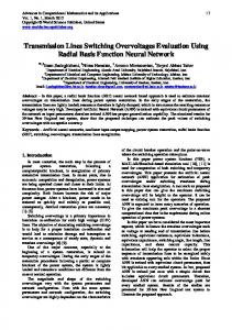
Fig. 7. System model in ATPDraw, using MODELS.
2500 P1-N1
2000
P2-N2
Voltage [V]
1500
4
Time [us]
6
8
10
Fig. 9. LIO across loads. TN-system. With arresters. Lightning location: Angle a=90º and distance r0=100m. 6000 5000
P1-N1
4000
P5-N5
P2-N2
3000
Voltage [V]
Fig. 8 shows the lightning induced voltages across loads at point 1, 2, and 5, with no arresters installed in the system. The loads (LVPI networks) are of TN type small (inductance of 10 mH). Fig. 9 shows the same simulation, but with arresters installed at all loads 2-6. The voltages at the other points 3, 4 and 6 are always lower then at point 5.
2
2000 1000 0
P5-N5
1000
-1000
500
-2000
0
-3000 0
-500
2
4
Time [us]
6
8
10
Fig. 10. LIO across loads. IT-system. No arresters. Lightning location: Angle a=90º and distance r0=100m.
-1000 -1500
3000
-2000 0
2
4
Time [us]
6
8
10
Fig. 8. LIO across loads. TN-system. No arresters. Lightning location: Angle a=90º and distance r0=100m.
Figs. 10 and 11 shows the same calculation as Figs. 8-9, but now for an IT system (without a neutral conductor). A
P1-N1
2000
P2-N2 P5-N5
1500
Voltage [V]
The voltage is highest across the transformer equivalent, reaching just above 2 kV, and this voltage is unaffected by arresters in the system. At load position 2, the voltage is limited by the surge arrester, and at the other positions 3-6 the voltage is below the protective level of the arrester. The voltage across the transformer in Fig. 8 is higher than across load in position 2 due to the lower grounding impedance of the transformer.
2500
1000 500 0 -500
-1000 -1500 -2000 -2500 0
2
4
Time [us]
6
8
10
Fig. 11. LIO across loads. IT-system. With arresters. Lightning location: Angle a=90º and distance r0=100m.
Figs. 12 and 13 show the maximum induced voltage across the load (ZT and ZLVPI) in the network in Fig. 4 (with a lightning distance r0=500) as a function of angle a. All the load types shown in tab. 1 are investigated. The transformer in point 1 is in all cases modelled with ZT = 10 mH. No arresters are installed in the system. The markers on the curves indicate where in the network (point 1-6) the maximum voltage occurs. UMAX [kV] 1.2 1: 10 mH 2: 5 mH 3: 2 mH
1
1
2
3
5
0.6 0.4 0.2
0
15
30
45
60
75
90
105
120
135
150
165
180
a [deg]
Fig. 12. Maximum LIO in TN system, dependency on LVPI model. Distance r0=500 m. UMAX [kV] 8
1
7
2
3
5
1: 50 nF+10 mH 2: 100 nF+5 mH 3: 200 nF+2 mH
6 5 4 3 2 1 0
0
15
30
45
60
75
90
105
·
Completely analytical expressions are established, and the calculation speed is limited by the convolution integrals performed in MODELS, taking the lightning current shape into account. The development of a type94 component would simplify the equivalent circuit further.
0.8
0
·
on the electromagnetic fields is more doubtful. Ignoring the lossy ground effects for nearby lightning (ta then if Tr>tb+L/c then Ui:=U0(x,Tr)*(f(x,Tr)-f(x-L,Tr-L/c)) else Ui:=U0(x,Tr)*(f(x,Tr)+1) endif else Ui:=0 endif if Tj=1 then UindA[Ti]:=Ui else UindB[Ti]:=Ui endif ENDFOR ENDFOR FOR Ti:=0 TO Tmax DO --Heidler current: Tr:=Ti*dt IF (Ti=0) THEN dI[0]:=0 ELSE e:=exp(-(T1/T2)*exp(ln(m*T2/T1)/m)) I:=Im/e*exp(m*ln(Tr/T1))/ (exp(m*ln(Tr/T1))+1)*exp(-Tr/T2) dI[Ti]:=I*((m/Tr)/ (exp(m*ln(Tr/T1))+1)-1/T2) ENDIF ENDFOR --Convolution integral. Small Io required!! Ti:=Tmax WHILE Ti>1 DO FOR Tr:=1 TO Ti-1 DO UindA[Ti]:=UindA[Ti]+ UindA[Tr]*dI[Ti-Tr]*dt
UindB[Ti]:=UindB[Ti]+ UindB[Tr]*dI[Ti-Tr]*dt ENDFOR Ti:=Ti-1 ENDWHILE --Possible to scale Uind Tr:=L/c ENDINIT EXEC UrAP:=UindA[t/dt]+ 2*delay(UBP,Tr-dt,1)-delay(UrBP,Tr,1) UrAN:=UindA[t/dt]+ 2*delay(UBN,Tr-dt,1)-delay(UrBN,Tr,1) UrBP:=UindB[t/dt]+ 2*delay(UAP,Tr-dt,1)-delay(UrAP,Tr,1) UrBN:=UindB[t/dt]+ 2*delay(UAN,Tr-dt,1)-delay(UrAN,Tr,1) ENDEXEC ENDMODEL
REFERENCES [1]
[2] [3]
[4] [5]
[6]
[7]
[8]
[9] [10] [11] [12]
[13] [14]
S. Rusck, Induced lightning over-voltages on powertransmission lines with special reference to the overvoltage protection of low-voltage networks, Royal Institute of Technology, PhD Thesis, Stockholm, Sweden, 1957. M.A. Uman, D.K. McLain, "Lightning return stroke current from magnetic and radiation field measurements", J. Geophys. Res., vol. 75, 1970, pp.5143-5147. C.A. Nucci et al., “Lightning return stroke current models with specified channel-base current: A review and comparison", J. Geophys. Res., Vol. 95, No. D12, Nov. 1990, pp. 20395-20408. R. Thottappillil, M.A. Uman, "Comparison of lightning return-stroke models", J. Geophys. Res., Vol. 98, No. D12, Dec. 1993, pp. 22903-22914. C.A. Nucci et al., "Coupling models for lightning-induced overvoltage calculations: A comparison and consolidation", Proc. of the 22nd Int. Conf. on Lightning Protection 1994, paper R3b-06, Budapest. A.K. Agrawal et al., "Transient respons of multiconductor transmission lines excited by a nonuniform electromagnetic field". IEEE trans. on EMC, Vol. 22, No. 2, May 1980, pp. 119-129. A. Zeddam, P. Degauque, “Current and voltage induced on telecommunication cables by a lightning stroke". Lightning Electromagnetics, R. Gardner (ed.), 1990, pp. 377-400. H.K. Høidalen, ”Lightning induced voltages in lowvoltage systems with emphasis on lossy ground effects”, Proc. int. conf on Power Syst. Transients IPST’97, pp. 336-341, June 22-26, Seattle. Alternative Transients Program (ATP) - Rule Book, Canadian/American EMTP User Group, 1987-1998. Dubé, Models in ATP, Language manual, Feb. 1996. L. Prikler, H.K. Høidalen, ATPDraw User’s Manual, SEfAS TR A4790, ISBN 82-594-1358-2, Oct. 1998. C.A. Nucci et al., "A code for the calculation of lightninginduced overvoltages and its interface with the Electromagnetic Transient Program", Proc. 22nd Int. Conf. on Lightning Protection 1994, paper R3b-05, Budapest. H.K. Høidalen, Lightning induced voltages in low-voltage systems, PhD thesis, ISBN 82-471-0177-1, University of Trondheim 1997. H.K. Høidalen, ”Lightning induced voltages in lowvoltage systems and its dependency on overhead line terminations”, Proc. Int. Conf. on Lightning Protection ICLP 1998, p. 287-292, Sept. 14-18, Birmingham.