This article has been accepted for publication in a future issue of this journal, but has not been fully edited. Content may change prior to final publication. Citation information: DOI 10.1109/ACCESS.2016.2619181, IEEE Access
MLP Neural Network based Gas Classification System on Zynq SoC Xiaojun Zhai, Amine Ait-Si-Ali, Student Member, IEEE, Abbes Amira, Senior Member, IEEE and Faycal Bensaali, Senior Member, IEEE Abstract — Systems based on Wireless Gas Sensor Networks (WGSN) offer a powerful tool to observe and analyse data in complex environments over long monitoring periods. Since the reliability of sensors is very important in those systems, gas classification is a critical process within the gas safety precautions. A gas classification system has to react fast in order to take essential actions in case of fault detection. This paper proposes a low latency real-time gas classification service system, which uses a Multi-Layer Perceptron (MLP) Artificial Neural Network (ANN) to detect and classify the gas sensor data. An accurate MLP is developed to work with the data set obtained from an array of tin oxide (SnO2) gas sensor, based on convex Micro hotplates (MHP). The overall system acquires the gas sensor data through RFID, and processes the sensor data with the proposed MLP classifier implemented on a System on Chip (SoC) platform from Xilinx. Hardware implementation of the classifier is optimized to achieve very low latency for real-time application. The proposed architecture has been implemented on a ZYNQ SoC using fixed-point format and achieved results have shown that an accuracy of 97.4% has been obtained. Index Terms— Artificial Neural Network; Gas identification; FPGA; System on Chip (SoC); ZYNQ.
I. INTRODUCTION
T
he oil and gas industry is one of the most dominant industries for the application of Wireless Sensor Technology [1]. For gas application, Wireless Gas Sensor Networks (WGSN) systems are used to observe and analyse sensed gas data in complex environments over long periods. As the accuracy of data and reliability of sensors are very important in those systems, a gas classification system has to react fast in order to take essential actions in case of fault detection. In order to have a system that reacts fast to the changes each processing element within the system has to work in a low latency manner [2]. Generally classifiers within This paper was submitted for the review on 26 th September, 2016. This research work was supported by National Priorities Research Program (NPRP) grant No. 5-080-2-028 from the Qatar National Research Fund (a member of Qatar Foundation). X. Zhai is with the Department of Electronics, Computing and Mathematics, University of Derby, Derby, DE22 1GB, U.K. (e-mail:
[email protected]). A. Ait-Si-Ali, A. Amira and F. Bensaali are with the KINDI Center for Computing Research, Qatar University, Qatar. (e-mail:
[email protected];
[email protected];
[email protected])
the gas sensor array system are the most computationally intensive processing components. Classifiers, such as neural networks, use the data set acquired from the gas sensor array system and process them to detect and classify gases and their properties within the gas chamber. Feed-forward artificial neural networks (ANN) are commonly used as classifiers for pattern classification approaches [3], which also include multi-layer perceptron (MLP). In general, software implementation of the MLP neural networks are used during the algorithm development phase, where parallel and low latency approach is not needed. However in real-world applications high speed processing and low latencies are needed in order to execute the ANN within the real-time constraints. The ubiquitous nature and miniaturization of sensor devices have revolutionized surveillance and monitoring systems. Now a single sensor node can be equipped with multiple sensors to collect data from different modularities. Since sensor nodes are becoming increasingly accurate they are employed to monitor subtle changes to the environment. In addition, machine learning techniques can be used to identify behavioural changes by analysing the data collected from sensor nodes, and generate an alarm signal that indicates abnormal behaviour. In this paper, a low-latency, real-time gas classification system is proposed. The service system uses a MLP ANN to detect and classify the gas sensor data. An accurate MLP is developed to work with the data set obtained from an array of tin-oxide (SnO2) gas sensor [2], based on convex Micro hotplates (MHP). The proposed system acquires the gas sensor data through RFID, and processes the sensor data with a novel low latency classifier within a heterogeneous ZYNQ Systemon-Chip (SoC) platform from Xilinx. ARM processor within the ZYNQ SoC acts as a host-processing platform that handles the data acquisition and transmission as well as the data distribution to and from the classifier. The interaction between the Processing System (PS) and the programmable logic (PL) is done with the use of the Direct Memory Access (DMA) accesses within the ZYNQ platform. The use of DMA engine provides the classifier the required bandwidth to be able to give the throughput required for the overall system. Finally hardware implementation of the MLP classifier is optimized to have very low latency and response time, in order to process
2169-3536 (c) 2016 IEEE. Translations and content mining are permitted for academic research only. Personal use is also permitted, but republication/redistribution requires IEEE permission. See http://www.ieee.org/publications_standards/publications/rights/index.html for more information.
This article has been accepted for publication in a future issue of this journal, but has not been fully edited. Content may change prior to final publication. Citation information: DOI 10.1109/ACCESS.2016.2619181, IEEE Access
TABLE I. SOFTWARE AND HARDWARE BASED GAS IDENTIFICATION SYSTEMS
Papers
No. Sensors
Target gases
Pre-processing
Classification
Implementation
[4]
8
CO, H2, CH4, CO-H2 & COCH4
EN & PCA
Committee machine: KNNs, MLP, RBF, GMM & PPCA
FPGA Celoxica RC203
[5]
8
CO, H2, CH4, CO-H2 & COCH4
EN
MLP
FPGA APS-X208
[6]
16
CO, H2, CH4 & C2H5OH
SOM
IM & LDA
PC
[7]
8
O3, LPG/LNG, NOX , Alcohol, Smoke, VOC, CO& NH3
SMA , Normalization between 0 and 1 & PCA
GA & ANN
Laptop, Zigbee & phone
[8]
8
CO, H2, CH4, CO-H2 & COCH4
PCA vs LDA vs NS
Density models: KNNs, GMM & GTM Discriminant functions: RBF, MLP and GLM
PC
[9, 10]
16
CO, H2 & C2H6O
LSTE
RO
ASIC
[11]
16
CO, H2 & C2H6O
With and without PCA
DT
FPGA (Xilinx Virtex II)+ ASIC
[12]
7 & 16
CO, H2, C2H6O, CO2, NH3 & C3H8
With and without PCA & LDA
DT
PC & Zynq SoC
the sensor data in real-time and to provide a sensible classifier output as fast as possible, which is a must in failure detection systems. In this paper an overview of the proposed system approach and an optimised hardware implementation of a feed-forward MLP neural network are detailed. The key features of the proposed work are optimizations to have a fixed-point parallel MLP system for the system level integration of the system. This paper aims to present a hardware implementation of a MLP classifier starting with some background work followed by the system description which includes neural network architectures and MLP classifier design. Then the details of FPGA implementation of an MLP algorithm are presented. Finally conclusions about the approached design and future work are included. II. RELATED WORK The gas classification problem has been widely addressed in the literature. A summary of various gas identification systems is presented in Table I, a comparison is made in terms of number of gas sensors used, target gases, pre-processing and classification algorithms as well as on the implementation platform. The pre-processing algorithms and classification algorithms used are the following: Euclidean normalization (EN), principal component analysis (PCA), linear discriminant analysis (LDA), neuroscale (NS), self-organized map (SOM), smoothed moving average (SMA), logarithmic spike timing encoding (LSTE), rank order (RO), k-nearest neighbors (KNNs), MLP, radial basis function (RBF), Gaussian mixture model (GMM), probabilistic principal component analysis
(PPCA), image moment (IM), genetic algorithm (GA), ANN, generative topographic mapping (GTM), binary decision tree (DT) classifier and general linear model (GLM). The types of implementation platforms used are mainly personal computer (PC), field-programmable gate array (FPGA), applicationspecific integrated circuit (ASIC) and Zynq SoC. In open literature many research papers have also been published about the use of FPGAs as the implementation platform for the MLP neural network for different applications. In [13], vitabile et al. implemented a MLP ANN that featured a virtual neuron based architecture with a target to have an optimized structure for high classification rate and minimum resource usage. The developed architecture was applied on high energy physics and road sign recognition algorithms. In [14], Yilmaz et al. implemented differential evaluation algorithm on an FPGA platform and cross compared with software simulations done in MATLAB. In [15], Alizadeh et al. implemented a ANN system that predicts cetane number in diesel fuel from the chemical compositions of the fuel by using the data from chromatography (LC) and gas chromatography (GC). In [16], Shi et al. implemented a gas discrimination system with the use of different classifiers on an FPGA platform. MLP was one of the classification algorithm which was implemented with the use of the tinoxide gas sensors. In [17], Latino et al. implemented a memory based MLP architecture on an FPGA platform to work with a smart position sensor system. In [18], Moradi et al. implemented an MLP for Farsi handwritten digit recognition algorithm on an FPGA platform
2169-3536 (c) 2016 IEEE. Translations and content mining are permitted for academic research only. Personal use is also permitted, but republication/redistribution requires IEEE permission. See http://www.ieee.org/publications_standards/publications/rights/index.html for more information.
This article has been accepted for publication in a future issue of this journal, but has not been fully edited. Content may change prior to final publication. Citation information: DOI 10.1109/ACCESS.2016.2619181, IEEE Access
Wireless Gas Sensor Networks (WGSN)
Remote & Hostile Wireless Gas Sensor Network Deployment
Gas Sensors Gas Sensors
FPGA FPGA
Gas Pipeline
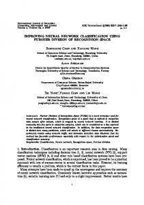
Fig. 1. Proposed system environment.
for speeding up an offline classification. In [19], Blaiech et al. proposed an efficient implementation of MLP neural network. Proposed a methodology to increase the efficiency of the implementation in terms of area and time, via an automatic generation of the MLP encoding. In [20], Ferreira et al. proposed an MLP architecture suitable to reduce the size of large ANN structures. The design is compared with software implementations. In [21], Bahoura et al. proposed a pipelined implementation to reduce the critical path and to increase the frequency of the design for an non-linear approximation ANN. III. SYSTEM DESCRIPTION The proposed system environment and its main component are illustrated in Fig. 1. The proposed system consists of a series of gas sensor nodes, where each of this node is equipped with a gas sensor acquisition unit and a FPGA unit. The gas sensor acquisition unit is used to monitor the specific gas molecules, and the FPGA unit is used to analyse and classify the gas categories. The processed information will then be sent to the monitoring centre through the WGSN using a multichip based approach. The block diagram of the proposed sensor node is shown in Fig. 2. The Overall system consists of a gas chamber where the gas sensor is present, data acquisition RFID transmitter and receivers, MLP classifier implemented on a ZYNQ platform, and a screen to show the system’s output. The sensor data is read from the gas chamber using the data acquisition block and transmitted to the processing platform through RFID [22]. In this particular application the Processing System (PS) is used to handle communication and control of the RFID block as well as the MLP classifier working on the PL. The final output of the overall system is the classified gas type from the trained neural network. The list of gases used during the data collection and training is: Benzene − C6H6 CarbonMonoxide − CO
Formaldehyde − CH2O NitrogenDioxide − NO2 SulfurDioxide − SO2
Gas Chamber
RFID
MLP Classifer
Data Acquisition
RFID
User Interface
Fig. 2. Proposed sensor node architecture.
A. Neural Network Architecture In this section, the notation, the ANN architecture and training process are explained. Neural networks have been widely used in pattern classification, completion, approximation, prediction and optimizations. The MLP is an ANN that consists of multiple layers of neurons in a feed-forward architecture. A multilayer perceptron consists of three or more layers where one input, one output and one or more hidden layers. MLP uses nonlinear activation function with the neurons and each layer is fully connected to the next layer. Several perceptrons are combined in order to create decision boundary with the use of nonlinear/linear activation functions. Each perceptron provides a non-linear mapping to a new dimension. Given that MLP is a fully connected network each neuron in each layer is connection to the next layer with a certain weight function wij. MLP uses a supervised learning technique called back propagation. During the training phase of the neural network
2169-3536 (c) 2016 IEEE. Translations and content mining are permitted for academic research only. Personal use is also permitted, but republication/redistribution requires IEEE permission. See http://www.ieee.org/publications_standards/publications/rights/index.html for more information.
This article has been accepted for publication in a future issue of this journal, but has not been fully edited. Content may change prior to final publication. Citation information: DOI 10.1109/ACCESS.2016.2619181, IEEE Access
> REPLACE THIS LINE WITH YOUR PAPER IDENTIFICATION NUMBER (DOUBLE-CLICK HERE TO EDIT) < weight function are defined. The training method for the MLP is based on the minimisation of the chosen cost function which is initially developed by Werbos [23] and Parker [24]. Input p1
Input Weights
Hidden Layer
p2
a11
p3
a21
p4
a31
Output Wights
Output
a12 a22
a32 ...
a1s2
pR-2
a1s1
...
... pR-3
4
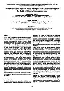
output neuron, where the 12 input neurons are corresponding to the 12 features extracted from each gas sample in a database that contains 600 gas samples. The neural network is trained by Levenberg-Marquardt backpropagation algorithm [26]. Fig. 4 shows the training performance of the ANN. This particular training uses 70% of the data for training, 15% of the dataset for testing and the remaining 15% for the validation. In general the hardware implementation of ANN system can hit to the PL’s routing capabilities quickly since it requires layer based connectivity. Thus operations and ANN structure are implemented in optimized way that utilizes PL’s routing and in fixed-point to limit the internal numerical precision which becomes a trade-off between hardware resources, calculation time and approximation quality.
ak22
ak21 pR-1
a
1 s
ak2 pR
Fig. 3. The architecture of the two-layer feed-forward network.
Fig. 3 is an example of an MLP network, where a hidden layer consists of S neurons and each neuron has R weights, which can be presented in a S×R matrix called Input Weight matrix I as shown in equation 1. The input vector P has R elements [p1, p2,…, pR]T, which are multiplied by I and the resulting matrix is summed with a bias vector b1 to form vector n1 as shown in equation 2. The output of the hidden layer a1 is the result of applying the transfer function on n1 (see equation 3). w1,1 w1,2 ... w1, R w2,1 w2,2 ... w2, R I (1) ...... wS ,1 wS ,2 ... wS , R
n1 I p b1
(2)
a1 f1 (n1 )
(3)
The same operations applied in the hidden layer are used in the output layer, which consists of K neurons, where a1 is used as the input vector (see equations 4, 5 and 6). w1,1 w1,2 ... w1, S w2,1 w2,2 ... w2, S L (4) ...... wK ,1 wK ,2 ... wK , S
n2 = L a1 + b2
(5)
a2 f 2 (n2 )
(6)
B. MLP Classifier The MLP algorithm which is a feed-forward ANN is modelled with two hidden layers and trained using the provided database [25]. The proposed feed-forward artificial neural network has 12 input neurons, three hidden neurons and one
Fig. 4. ANN training performance.
The choice of the number of hidden layers is based on the performance of the ANN over the testing of using different hidden layers. Given the desired output of the ANN system is an integer which indicates the classified gas type, ANN with higher number of hidden layers tends to have very good performance during the training however they have bad performance with the validation stage. The optimal point for the ANN is chose where validation stage has the lowest Mean Square Error (MSE) value. IV. HARDWARE IMPLEMENTATION The MLP ANN training phase was done in MATLAB simulation environment. Since the data set and the gas sensors are not changing dynamically. Training is proposed to be done by recorded data and according to the training results. The implementation of the trained weight data is done using signed fixed-point representation 24-bit total length with 20 fractional bits. The activation function which has been used within the MLP algorithm is implemented with the use of look-up tables (LUTs). Different variations have been performed to obtain the optimum implementation for this component, however in order to reduce the latency, the distributed memory is chosen. The proposed parallel design can be described as a parallel data-flow architecture, where every neuron in every layer has one processing element (PE). This approach allows the system
2169-3536 (c) 2016 IEEE. Translations and content mining are permitted for academic research only. Personal use is also permitted, but republication/redistribution requires IEEE permission. See http://www.ieee.org/publications_standards/publications/rights/index.html for more information.
This article has been accepted for publication in a future issue of this journal, but has not been fully edited. Content may change prior to final publication. Citation information: DOI 10.1109/ACCESS.2016.2619181, IEEE Access
> REPLACE THIS LINE WITH YOUR PAPER IDENTIFICATION NUMBER (DOUBLE-CLICK HERE TO EDIT)
+5, the values of tanh(x) is closed to -1 and +1 respectively. When -5 ≤ x ≤ +5, the values of tanh(x) have been pre-calculated for using samples of x in this range {-5, 4.99,…,4.99,5} where a step size 0.01 is used.
In the feedforward computation perspective, the multiaccumulation operations will occupy the most of the computation time. So we will focus on accelerating input and hidden layers. The objective of computation optimisation is to enable efficient loop unrolling or pipelining while fully utilisation of all computational resources provided by the FPGA on-chip hardware. The used optimisation pragmas are highlighted as follow: Loop Unrolling: The loop unrolling strategy can be used to increase the utilisation of massive computation resources in FPGA devices. Depending on the way to unroll along different loop dimensions, the implementation variants will be generated. The complexity of the generated hardware will be
Fig. 7. Sigmoid Function.
i1 w1 i2 w2 i3 w3 i4
+ ×
+
× +
×
+
i11 w11 i12 w12
...
...
w4
×
To Activation Function
× + ×
2169-3536 (c) 2016 IEEE. Translations and content mining are permitted for academic research only. Personal use is also permitted, but republication/redistribution requires IEEE permission. See http://www.ieee.org/publications_standards/publications/rights/index.html for more information.
This article has been accepted for publication in a future issue of this journal, but has not been fully edited. Content may change prior to final publication. Citation information: DOI 10.1109/ACCESS.2016.2619181, IEEE Access
> REPLACE THIS LINE WITH YOUR PAPER IDENTIFICATION NUMBER (DOUBLE-CLICK HERE TO EDIT)
REPLACE THIS LINE WITH YOUR PAPER IDENTIFICATION NUMBER (DOUBLE-CLICK HERE TO EDIT) < and R smaller arrays respectively, where S and R is the number of hidden and input neurons respectively. The major benefit of doing this is to ensure all the data within the arrays can be fed into the parallelised multipliers, to be executed at the same time. The achieved synthesised architecture confirmed that the desired initiation interval for the pipeline pragma achieves one initiation, which has greatly reduced data dependencies of input arrays. During the conversion process several criteria can be considered, such as MSE, size of neural network, memory requirements. The absolute error calculated by the difference between success rates in fixed-point coding and floating-point coding reflects the performance criterion of our MLP. During the fixed-point conversion process, we determined the integer and fractional part of the MLP after the arithmetic conversion, which took the floating point double precision and converted to 2’s complement with 24 bit total length with 20 fractions. As a result of this, the performance of classifier with fixedpoint implementation remained same as 96.8% correct classifications from the MATLAB implementation. The ARM processor runs at 650 MHz and the PL clocked at 100 MHz. The processing time of the proposed system is measured by counting the number of ARM processor’s clock cycles spent for obtaining the classified results of one Gas signal from the MLP accelerator. Table III shows the comparison between the software and hardware implementations of the MLP accelerator in terms of the processing time. As it can be seen in Table III, the average processing time using the hardware implementation has improved by a factor of 31 compared to the software implementation on a dual-core Intel i7-5600U CPU at 2.6 GHz. TABLE III.
PROCESSING TIME OF THE MLP ACCELERATOR
Hardware Implementation (us)
Processing time
0.5397
TABLE IV.
Static Power Consumption
17
Factor
31
ESTIMATION OF POWER CONSUMPTION
Utilization Details
Dynamic Power Consumption
PC Software Implementation (us)
Power (W)
power, logic power, signal power, BRAMs power, etc., which are directly affected by the chip clock frequency and the usage of chip area. The details of estimated power consumption of the implementation are summarised in Table IV. The PS7 consumes much more power than the PL; this is due to the fact that the ARM dual core Cortex-A9 based processing system has much higher running frequency than the PL and it runs drivers and control programmes. Compare to the PS7, the custom logic blocks consumes only a small portion of the total on-chip power consumption. To measure the performance of MLP neural network across the wide range of platforms that they have been implemented on, one of the common criteria is: connections per second (CPS), where the connections stand for one term in the sum of
0.009
1
Signals
0.025
2
Logic
0.019
1
DSP
0.028
2
BRAM
0.004
REPLACE THIS LINE WITH YOUR PAPER IDENTIFICATION NUMBER (DOUBLE-CLICK HERE TO EDIT)
REPLACE THIS LINE WITH YOUR PAPER IDENTIFICATION NUMBER (DOUBLE-CLICK HERE TO EDIT)