Abstract Mobile data networks offer a cost-effective and efficient alternative for data communication. In order to present some aspects of mobile data technology, this article offers some insight into the basic networking layers of a popular and widely deployed network, MOBITEX. MOBITEX technology offers a versatile architecture to support wireless packet data service inside an extended geographical area with internetwork roaming and interoperability features. This technology has become quite popular, mainly due to its open architecture and its vast equipment/applications availability. The authors provide an overview of the MOBITEX architecture, services, and subscription types, and a detailed examination of the network, data link, and physical layers. The power-saving features of MOBITEX are also discussed.
Mobile Packet Data Technology: An Insight into MOBITEX Architecture Apostolis K. Salkintzis and Christodoulos Chamzas Democritus University of Thrace
D
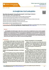
ates at a raw data rate of 19.2 kb/s and provides forward error correction to combat the interference and fading of cellular channels. MOBITEX wireless data networks are becoming widely accepted all over the world. MOBITEX technology has become a true worldwide de facto standard. In the United States, RAM Mobile Data (RMD) operates MOBITEX systems nationwide in 7700 cities and towns, covering over 90 percent of America’s urban business population, and over 11,000 mi of interstate highway, with automatic seamless roaming across all service areas [5]. Furthermore, additional coverage is being implemented now in order to expand the service area in the near future. MOBITEX networks are either installed or being deployed in 16 countries on five continents, including Canada, the United Kingdom, France, Sweden, Finland, Norway, Belgium, the Netherlands, and Australia. There is a MOBITEX Operators Association (MOA) to oversee the specifications, coordinate software and hardware development, and further evolve technology. The specifications are published by the MOA without any license or fee; thus, there are a number of terminal suppliers and equipment developers. The primary reason that mobile data has managed to withstand the cellular (again, we refer to the cellular phone networks) competition so far, is the increased performance of data transmission. Mobile data systems are designed for packetswitched (“asynchronous”) rather than circuit-switched (“isochronous”) operation, the latter being the case for data over cellular. Therefore, communication resources are more efficiently utilized, resulting in superior overall performance and lower cost. Mobile data Figure 1 illustrates how the cost Cellular of data transmission over mobile data and cellular networks changes relative to the size of data per transSize of data mission [6]. The figure is only repreper transmission sentative and aims at revealing that mobile data networks are most cost ■ Figure 1. Comparing the cost of data transmisefficient when small quantities of sion over mobile data and cellular networks. data are transmitted at one time.
espite the explosive evolution of the cellular1 industry during the past decade, mobile data networks keep on spreading and providing data services to numerous subscribers all over the world. This is shown by the fact that the most important wireless packet data networks, namely, MOBITEX, ARDIS, and CDPD (cellular digital packet data), are facing increasing activity in many areas, including technical and business. ARDIS (Advanced Radio Data Information Service, a subsidiary of Motorola) is one of the biggest wireless data service providers in the United States. It employs RD-LAP technology and offers wireless packet data messaging service in over 400 metropolitan areas in the United States, Puerto Rico, and the Virgin Islands, and covers about 90 percent of the urban business population [1]. The network was initially created as a private network for IBM and was later made available for public use (as a 50/50 joint venture between Motorola and IBM [2]), offering 19.2 kb/s signaling in 25 kHz channels, wide roaming, robust link layer and coding schemes, and significant overall message throughput. IBM is still ARDIS’ largest customer, with more than 12,000 field engineers using the ARDIS network. RD-LAP architecture has also spread to other countries, including Canada and Germany. CDPD [3] is a new technology that has begun to spread, although perhaps not as rapidly as expected [4]. In the first nine months of 1995, CDPD service availability climbed from 12 metropolitan statistical areas (MSAs) to 49, and at the end of the year it reached over 50. CDPD was Cost introduced by IBM as a packetswitching overlay to the existing analog cellular voice network and frequencies. This technology uses idle voice channels to multiplex short data messages and to hop among the available frequencies to find those idle channels. The air interface oper1
It is customary to use the word “cellular” to refer to cellular phone networks like AMPS and GSM.
10
1070-9916/97/$10.00 © 1997 IEEE
IEEE Personal Communications • February 1997
Computerized dispatch center
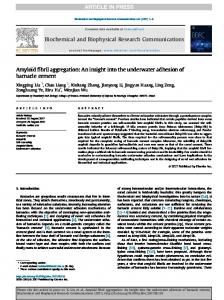
Transporting data over cellular, however, becomes most cost efficient when large data transfers are taking place in each transaction. Another major advantage mobile data networks have over cellular is their store-and-forward capabilities. With cellular the wireless terminals have to be continuously attached and working to receive messages,2 whereas with mobile data messages are stored even when the radio modem is switched off or out of radio coverage, so there is no always-in-contact requirement. From the user perspective, mobile data systems offer an alternative that usually guarantees both cheaper and improved services (as compared to cellular) in a wide range of packetdata applications such as wireless messaging, remote data collection, remote database access, wireless credit card verification, automatic vehicle location, computerized dispatch, and Internet access (Fig. 2). All these applications drive the market of the present mobile data networks. Prospective customers include companies such as couriers, emergency services, taxis, and trucking that need a system to provide accurate, real-time vehicle and driver status, routing and scheduling, and two-way communication between drivers and dispatchers. Furthermore, companies that use applications such as e-mail, remote data access, data collection, and point of sale need a system to connect their mobile workforce to a central computer without the constraints of wired telephone connections. Mobile data networks bring new opportunities to these businesses without excessive cost requirements. The rest of this article presents some insight into the operational aspects of mobile data networks by describing the basic networking layers of a popular and widely deployed network, the MOBITEX.
MOBITEX System Architecture he MOBITEX architecture was originally developed by Swedish Telecom, now called Telia Mobitel, as a private mobile alarm system used by field personnel. However, mainly for economical reasons, it evolved into a public mobile radio service. Continuing development has been done by Eritel AB under the guidance of the MOA and Ericsson Mobile Communications AB. Commercial operation was introduced in Sweden in 1986; since then, a number of networks have been constructed in Europe, the United States, and Australia [2, 5]. Only the radio frequency differs, depending on the country: 900 MHz is used mainly in the United States and Canada; most other countries operate in the 450 MHz range. In the rest of this section the main functional elements of the MOBITEX network and the interfaces between these elements are defined. The MOBITEX system employs a cellular layout in order to provide wireless communication services to a specific geographical area. It utilizes a hierarchical structure that may contain up to six levels of network nodes depending on the size and the area of coverage. As shown in Fig. 3, the infrastructure comprises three types of nodes: base stations (Base), local switches, and regional switches. The cells served by the same local switch form a service area or subnet. In each service
T
Credit card automated point-of-sale program Central office
MOBITEX
Service/delivery personnel
Wireless credit card verification
Wireless messaging
■ Figure 2. Common applications of mobile data networks. area 10 to 30 frequency pairs (called channels) are allocated to radio service [5]. Each base station usually utilizes from one to four channels, depending on the anticipated cell loading. All these channels have 12.5 kHz bandwidth and support a data rate of 8 kb/s. The allocated RF spectrum in the United States is 935 to 940 MHz for the downlink (base to mobile) and 896 to 901 MHz for the uplink (mobile to base). The base stations are connected to local switches via local
Network control center
Other regional switches
Main exchange Regional switch
Regional switch
Other regional switches
Local switch
Local switch
Local switch
Regional switch HDLC or X.25 line Local switch
Local switch
Local switch
Fixed terminal
Mobile terminal 2
In order to fulfill this objective, a number of complicated errorcorrecting protocols have emerged such as Microcom’s MNP-10, AT&T’s ETC (Enhanced Throughput Cellular), Celleritas’ TXCEL (though not actually a protocol), and V.42 and V.34.
IEEE Personal Communications • February 1997
Base
■ Figure 3. MOBITEX hierarchical archictecture.
11
4-7 Layers
Data MPAK
3-Network MPAK
MPAK
MPAK
2-Data link MASC
MASC ROSI
ROSI HDLC
HDLC X.25
RS-232 GMSK
GMSK X.21
X.21
Portable or mobile Radio modem terminal
Base station
1-Physical
RS-232
X.21
Local switch
Radio terminal
■ Figure 4. Protocol layering in various network elements. telephone facilities using either X.25 or a high-level data link control (HDLC) data link. Similarly, the local switches are connected to higher-level nodes (regional nodes) via long distance facilities and usually employ the same data link protocols. At the head of the hierarchy lies the main exchange which interconnects with other networks. Finally, another network element, the network control center (NCC), supports network-wide management and supervision functions. A key feature of the network is that message switching occurs at the lowest possible level (not the case for other networks, e.g., CPDP), ensuring quick response times and reduced backbone traffic. In other words, communication between two mobile users inside the same cell involves only the cell’s base station. If mobile users roam in different cells belonging to the same service area, message turnaround occurs at the service area’s local switch. Only mobility, authentication, and other signaling messages need to travel upwards in order to maintain proper operation. Furthermore, if the link between a base station and its superior switch is lost, the base station may still operate in autonomous mode, where it handles only intracell communications. This feature is supported by Ericsson’s BRS2 base stations [7]. Another key feature of MOBITEX is store-and-forward capabilities. A temporary store-and-forward facility allows applications to deal more effectively with mobile units that are temporarily unavailable (e.g., turned off or in a tunnel). Each registered subscriber has a storage space allocated within the MOBITEX system (a mailbox). If a packet is undeliverable, it may, at the sender’s discretion, be stored in the recipient’s mailbox. When the recipient’s radio modem reestablishes contact with the system, it automatically registers with a base station and all the accumulated packets in his mailbox are then forwarded to him.
Subscriptions Network subscribers can access the network services through a physical network access point, that is, either a fixed host terminal (connected to a local switch, see Fig. 3) or a radio terminal which complies with the MOBITEX air interface specification [8]. Standard connection interfaces are specified for both types of access terminals in order to establish a standardized access platform. The MOBITEX system supports various types of subscriptions to efficiently accommodate a wide range of applications
12
and requirements. Generally, every fixed host needs a host terminal subscription; similarly, every radio terminal is associated with a mobile terminal subscription. Whenever a radio terminal is switched on, it uses its own subscription profile to register with the nearest base station and to log into the MOBITEX system. During this Data phase the radio terminal transmits its Electronic Serial Number (ESN), which is hard-coded into MPAK each radio modem, and the network verifies that the transmitted ESN matches the ESN stored in X.25 its subscription profile. Any mismatch triggers an alert to the NCC, and a command is sent to the radio terminal, rendering it inactive. Furthermore, every individual who needs access to the MOBITEX must have a personal Fixed host subscription. Every personal subscription is associated with a PMAN (personal MOBITEX access number) and a password, which protects from unauthorized use and helps with correct billing. In order to access the network a person must use the nearest access terminal (radio or host terminal) to request login using his own PMAN and password. The access terminal transmits the login request to the network side for authentication. In this way, the network finds out the physical access point (i.e., the address of the employed radio or host terminal) of every logged-in personal subscription, and thus can subsequently route the subscription’s incoming traffic appropriately. Up to eight personal subscriptions may be active on a radio terminal at a time. It is to be noted here that the utilization of both mobile terminal and personal subscriptions effectively offer personal mobility (a significant concept in personal communications), because a person is not bound to a specific terminal. In every case, a person may select and use a preferred (and maybe different) terminal to gain access to the network. Additionally, there are group subscriptions that comprise a number of mobile and host terminal subscriptions and are used for receiving group messages (e.g., from all the field workers of a company). This service minimizes the work of dispatch personnel by broadcasting identical messages to numerous subscriptions. A group broadcast message is sent to terminals in a controlled geographical area selected by the customer. There is no definite acknowledgment from each recipient of a group broadcast message, so there is no guarantee that a radio terminal will receive the message. However, the network will broadcast a group message several times. Lastly, there are host group subscriptions that enable a mobile user to access a group of host computers as if they were a single host, or allows a single host to have multiple network appearances (for a detailed description see [5]). The addresses used to identify subscriptions, groups, and external networks are called MOBITEX access numbers (MANs).
Protocol Layering Figure 4 shows a layered picture of the MOBITEX interfaces. It is evident, that the MOBITEX architecture is associated only with the first three layers of the open systems interconnection (OSI) model. However, the three protocol layers of MOBITEX are not clearly mapped into the corresponding OSI layers. For example, in the physical layer of MOBITEX an error correction coding is defined, which is not a physicallayer function in the OSI model. Layers four to seven are employed and controlled by the applications using the network. The mobile terminating unit (i.e., the radio modem) inter-
IEEE Personal Communications • February 1997
8
faces with a mobile or portable terminal from one side and with the MOBITEX infrastructure from the other side, through the air interface protocol. Both these interfaces are standardized by MOA, and their specifications are extensively described in [8]. The interface between the mobile/portable terminal and the radio modem is either physical or logical in cases where both elements are implemented in a single physical unit. The standard MOBITEX (mobile/portable) terminal interface is called MASC (MOBITEX ASynchronous Communication). This interface provides for both the reliable transfer of data to/from the radio modem, and the control and status monitoring of the modem. The rest of this article focuses on the air interface protocol, describing the main features of the network layer (MPAK), the data link layer (ROSI – Radio OSI protocol), and the physical layer.
7
6
5
4
3
2
Octet 1
Sender
2
Sender
3
Sender
4
Addressee
5
Addressee
6
Addressee Rese rve Subscription flags
7
Traffic state 8 Packet class ExterPacket type nal 9 Number of addresses
1
Bits
Header
Address list
Type-dependent part
Network Layer lthough the MOBITEX specification defines both packet- and circuit-switched (mainly for voice communication) transmission facilities, most operators are restricted to data communications and provide only packet-switched services. This is why the MOBITEX is mainly classified as a mobile data network despite the initial provision for voice communications. Generally, traffic at the network layer is used either to transfer information from one subscriber to another (consider two-way messaging), between applications (e.g., on credit card verification), or to update information resources stored in network specific elements (e.g., login-logout indications). Data packets are divided into four classes according to the type of service they are engaged in: • PSUBCOM-class packets transfer information from one subscriber (or application) to another, such as text messages, data messages, status messages, and higher protocol data messages. The message type is encoded in the type field of a packet, so the network elements and applications can treat the various types accordingly. • PSOSCOM-class packets are used to transfer alert messages (i.e., high-priority data traffic). • CSUBCOM-class packets are used to set up and control circuit-switched connections (to support real-time connections). These kinds of packets are not used in data communication, so we do not pay any further attention to this class. • DTESERV-class packets are basically network-layer signaling packets used to update status information. For example, they are used to change the status of personal and group subscriptions (e.g., login, logout requests), to change a terminal’s status (e.g., active-inactive messages), and to transfer terminal-specific information (e.g., terminal information request/response) to the network. The network-layer protocol unit in MOBITEX is named MPAK (MOBITEX PAcKet), the general structure of which is shown in Fig. 5. The packet header is composed of three parts; the first is mandatory to all MPAKs, while the other two are optional and type-dependent. As shown in Fig. 5, the mandatory part is octets 1–8. When a packet is destined to multiple individual recipients, the second part contains the address list of these recipients. The third (type-dependent) part is included only in various packet types where additional information is required to support a given service. The fields sender and addressee inside an MPAK contain the subscription numbers (MANs) of the originator and recipient of the packet. The sender MAN can be a terminal sub-
A
IEEE Personal Communications • February 1997
Data field
■ Figure 5. MPAK structure. scription, personal subscription, or network MAN, while the addressee MAN may be all these plus a group MAN. Traffic state flags represent the transfer status of a message and are checked during an MPAK reception. They encode various error conditions in cases where a packet is undeliverable (e.g., congestion, bad format, network busy). If traffic state flags indicate no error (traffic state = 0), the received MPAK is forwarded to the ultimate destination: the upper layer or the network-layer management entity. Furthermore, if a message comes from a user’s mailbox (placed earlier, when the user was unavailable), the traffic state flags will indicate this. Also, if we are attempting to transmit a packet to a recipient who is currently unavailable, the packet will be placed in a recipient’s mailbox for future delivery, and will return with the traffic state flags indicating so. Subscription flags are set by the packet originator to define whether the packet may or may not be stored in the recipient’s mailbox, if a positive acknowledgment for this packet is needed (packets are by default not acknowledged at the network layer), if the packet contains an address list inside, and so on. Finally, the packet class associates the packet with one of the four classes mentioned above, PSUBCOM, PSOSCOM, DTESERV, and CSUBCOM, and the packet type specifies an individual type within the designated class. For example, a text message will have PSUBCOM class and type = 1, while a data message will have the same class but type = 2. Similarly, if we try to log in, the login request message will have DTESERV class and type = 1. A unique feature of MOBITEX is the possibility to forward one packet to a number of recipients. In order to efficiently utilize radio resources, the originator does not transmit multiple copies of the same packet, but only one packet, which includes the desired recipient list in the header. The direct addressee for this packet is the MOBITEX network (this is a special address). The first network node that receives the packet (i.e., the selected BASE station) will split the packet into a number of individual packets, each addressed to a recipient included in the original address list. Afterwards, each packet is separately switched through the wireline or wireless facilities.
13
MPAK header
User data
Mobitex packet (MPAK) Free bits
for a particular frame. It should be noted that a frame is transmitted only after the previous one has 24 8 8 8 96 16 144 16 16 144 16 been acknowledged (i.e., a stopLink MOB Frame Bytes free Block MPAK CRC MPAK CRC MPAK CRC layer and-wait ARQ scheme is employed MAN ID & seq no. length data data data frame at the frame level). Primary block Block #1 Block #2 The data link protocol of 20 bytes 20 bytes 20 bytes MOBITEX is quite different and 240 16 16 6 6 4 8 240 240 simpler than the data link protocol Base Area Ctrl Physical layer of CDPD. The latter is HDLCPreamble SYNC Parity Block #1 Block #3 Block #2 ID ID flags frame based (similar to International Parity Parity Parity Telecommunications Union — Frame head Telecommunications Standardization Sector, ITU-T, Recommenda■ Figure 6. MOBITEX frame structures. tion Q.921) and establishes data link connections between the mobile terminals and the network, Data Link Layer whereas, the former is a custom connectionless protocol. Both, however, employ error detection/correction schemes and selective retransmissions. he data link layer specifies the functions used to provide efficient, error-free transmission over the wireless mediChannel Access um. It mainly provides the functionality of the data link layer as defined in the OSI model. It implements functions for The multiple access protocol in the MOBITEX is a variation error detection and correction through a block-selective ARQ of the well-known slotted ALOHA [9]. A mobile terminal scheme, channel multiaccess algorithms, priority facilities and (MOB) that has traffic to send is allowed to transmit only roaming procedures. Generally, the data link layer ensures during specific free cycles.4 These cycles (repeated time periproper communication with the MOBITEX infrastructure ods) are initiated by the base station in every cell, by transmit• By selecting the most suitable (in terms of communication ting a FREE frame on the downlink. The free cycles are reliability) base station with which to communicate divided into slots of equal length. After a FREE frame recep• By retransmitting data link structures that either were tion, a ready MOB (one with awaiting traffic) randomly destroyed by the mobile data channel impairments or colchooses a slot and starts transmission at the beginning of that lided with neighbor transmissions slot. If an MOB becomes ready during a free cycle, it trans• By efficiently accessing the shared transmission resources mits at the next available slot. Of course, due to random available for communication access, collisions may occur when two or more MOBs choose The general link layer frame structure used in MOBITEX, the same slot to transmit. is shown in the middle of Fig. 6. It consists of a series of The slot length (SLOT_LENGTH) as well as the total numblocks, each one with a constant size of 20 bytes and each ber of slots (FREE_SLOTS) in a free cycle are explicitly stated with a 16-bit CRC (cyclic redundancy check) appended at the in the FREE frame that initiated the cycle. Both these variend for error protection. ables can change depending on the amount and length of The first block is the primary block and contains mandatodownlink traffic. The SLOT_LENGTH parameter in the FREE ry link control information. The link address (MOB MAN) at frame actually specifies the maximum length of a data frame the beginning specifies the address of a mobile terminal which that can be sent without a preceding access request. To either has generated the frame or is the immediate destinaexplain this further, consider an MOB that has a data frame tion of the frame. Additionally, the primary block specifies the to send. If the total length of the frame is greater than the type of the frame, the number of blocks in the frame, the SLOT_LENGTH parameter specified in the previous FREE sequence number of the frame, and the number of valid bytes frame, it must send an access request instead of the data in the last block.3 A data link layer frame may comprise only frame itself. At the end of the free cycle the BASE will grant access permission to every mobile that has successfully sent an the primary block; the following blocks may or may not exist access request. Thus, one after the other, the mobiles will depending on the frame type. For example, in Fig. 6, two eventually transmit their data frames (though outside of a free blocks were required after the primary, in order to transfer an cycle) before the next free cycle. MPAK. In acknowledgments, however, only the primary block In Fig. 7a, 5 free slots are illustrated with a length of 70 ms is necessary. each. In this example, MOB 1 generated the random number The data link layer employs a block selective repeat auto“2” and sent a status message in the second slot, while MOB 2 matic repeat request (ARQ) scheme to efficiently recover generated the random number “4” and sent an access request from transmission errors. That is, after a frame transmission (ABD). At the end of the free cycle the BASE acknowledges (say from mobile to base) the addressee checks the received the status message of MOB 1 and also grants access permisblocks for errors. If all the blocks are correct, it replies with sion to MOB 2 by transmitting a (properly addressed) access an ACK frame (positive acknowledgment); otherwise, it grant frame (ATD). replies with a repetition request REB frame that explicitly In Fig. 7b another channel activity example is shown. indicates which blocks have to be retransmitted. There may be Because the base station operates in full duplex it can simultacases, for example, when the primary block is corrupted or a neously receive and transmit messages. The base station frame is addressed to a group, where a recipient should not attempts to make the most efficient use of air time by arrangtransmit an acknowledgment. Actually, there is a single flag in the link header that indicates if an acknowledgment is needed
T
3
Remaining bytes in the last block are filled with zeros.
14
4 This is a main characteristic of MOBITEX. Other mobile packet networks such as CDPD allow terminals to transmit at any time.
IEEE Personal Communications • February 1997
SWEEP FREE
ACK to ATD to MOB 1 MOB 2
SWEEP
ing messages by size and coordinating with the inbound traffic from the From base 1 2 3 4 5 mobiles. Considering Fig. 7b, after From mobile SLOT_LENGTH=70 msec the first FREE frame, the base staFREE_SLOTS=5 (a) tion transmits a message to MOB 3 Status ABD and also generates six random access from from slots. To increase channel efficiency, MOB 1 MOB 2 the duration of random slots is made approximately equal to the duration ACK to ATD to ACK to of the outbound message to MOB 3. MOB 1 MOB 2 MOB 2 FREE FREE Message to MOB 3 Message (2) to MOB 3 After the free cycle ends, MOB 3 acknowledges the message sent by From base 1 2 3 4 5 6 BASE and the BASE responds to From mobile the packets sent by MOB 1 and MOB 2 (with an ACK and ATD, (b) Message from MOB 2 Status ADB ACK ACK respectively). Afterwards, MOB 2 from from from from sends its long message packet (it has MOB 1 MOB 2 MOB 3 MOB 3 been granted channel access), and simultaneously the base station ■ Figure 7. Channel access timing. sends a second message to MOB 3. It then sends an acknowledgment in response to the long message from MOB 2 and also receives strength in these channels. This average value is often referred an acknowledgment frame from MOB 3. to as the roaming value of the channel. An important characteristic of the channel access proceInside every cell, many variables related to the scanning dure is that transmit permission in a free cycle may be given and channel measurement processes are broadcast by means only to a subset of mobiles, in order to reduce the number of of special signaling frames. The most important frame belongaccess attempts. This is accomplished by either addressing the ing to this category is the SWEEP frame, which contains many FREE frame to a number of mobiles (using a specific address parameters needed for operator-assisted roaming. An MOB mask field), specifying a priority level (above which transmit that receives a valid SWEEP frame from BASE will update permission is granted), or specifying a particular traffic type some internally maintained parameters and will also mark the (alert, data, etc.) that is acceptable in the free cycle. start of a new sweep cycle. Figure 8 illustrates the format of a Every data frame (or access request) transmitted by a (type 1) SWEEP frame. MOB during a free cycle must be acknowledged by the BASE The primary block is always present in a SWEEP frame, before the next FREE frame (i.e., before the start of the next but the following blocks may or may not exist. Whenever they free cycle). Frames that have not been acknowledged (maybe exist, these blocks identify a list of neighbor system channels because they have collided) are retransmitted using a repetithat should be monitored by the MOBs in a specific cell. tion policy managed by the network operator. Generally, an Thus, every MOB may use these blocks to maintain in memoMOB has to wait for k free cycles before retransmitting. The ry a neighbor (or current channel) list5 for roaming purposes. It specified default value for k is zero (i.e., retransmission may is the job of the network operation center to properly configoccur at every free cycle); however, k may become progresure every BASE relative to how often this channel list will be sively larger as the repetition number increases (for a combroadcast and which channels will be included in the list. plete backoff policy description see [8]). Finally, if too many The ordinary roaming procedure implemented by every repetitions have been tried, the data frame is returned to the MOB is as follows (Fig. 9): After the reception of a SWEEP network layer and a recovery mechanism is triggered (usually frame some internal parameters including the current channel a roaming procedure) in order to re-establish a reliable data list are updated. Also an internal timer, T s, is started as an link contact. indication of a new sweep cycle beginning. The concept of sweep cycle is important in the MOBITEX system; it specifies Roaming a time period in which a roaming procedure takes place. At the end of a sweep cycle, all the neighbor channels are evaluThe portion of the data link management entity that is responated and the best BASE station is chosen. A typical sweep sible for finding the best network access point (i.e., base stacycle duration is 10 s. tion) and retaining the best radio link quality possible is called Timer Ts will time out after a period t which depends on the roaming entity. Usually, the roaming entity deploys the primitives provisioned by the first two or three layers of the the terminal’s own subscription number6 (MAN) according to OSI network reference model. the following relations: The main roaming procedure is somewhat similar in every t = TIME_TO_NEXT – 10 ms – SCAN_TIME, cellular network with roaming capabilities. That is, a mobile if MAN is even or station monitors the quality of the currently selected radio channel as well as the quality of other system channels which t = TIME_TO_NEXT – 10 ms – 2*SCAN_TIME, are highly likely to provide an acceptable radio communicaif MAN is odd tion. The main differences that exist in various approaches 5 Every MOB also holds a default channel list in nonvolatile memory include the way “quality” is translated, the means for quality measurement [10], and the frequency of these measurements. which contains all the network system channels. If the current channel list MOBITEX roaming procedures generally conform to the is not available, the default channel list is used. above principle. Every MOB, in addition to monitoring the 6 Partitioning the mobile terminals in this way ensures that data traffic can signal quality of the currently registered base station (the CURRENT_BASE), is periodically scanning other system chanbe forwarded to terminals with even (odd) MANs while terminals with odd nels and evaluates the average value of the received signal (even) MANs are in the midst of normal channel monitoring.
IEEE Personal Communications • February 1997
15
MOB(24bits) PRIO(3)
000
01111
BLOCK(8)
MASK(5)
TYPE(8) = 1
Tx POWER(8)
RSSI_PROC(8)
RSSI_PERIOD(8)
TIME_TO_NEXT(8)
MAX_REP(8)
BASE_STATUS(8)
SCAN_TIME(8)
BAD_BASE(8)
GOOD_BASE(8)
BETTER_BASE(8)
00000000 CRC(16 BITS) 00000000
channel 1 - UPFREQ(8)
channel 1 - DOFREQ(8)
channel 2 - UPFREQ(8)
channel 2 - DOFREQ(8)
channel 3 - UPFREQ(8)
channel 3 - DOFREQ(8) Block #1
channel 4 - UPFREQ(8)
channel 4 - DOFREQ(8)
CRC(16 bits)
■ Figure 8. Type 1 SWEEP frame format. where SCAN_TIME is the overall length of the neighbor-channel scanning period (including channel switching) and TIME_TO_NEXT is the interval before the next SWEEP frame. All these parameters are defined in the primary block of a SWEEP frame (Fig. 8). System channels specified in SWEEP frames are scanned by the MOB in a round robin fashion, and a roaming value is evaluated for each one. As indicated in Fig. 9, normal channel monitoring starts as soon as timer T s times out. During the SCAN_TIME period the MOB leaves the current channel, tunes to the next system channel in turn for a period specified by the RSSI_PERIOD, and measures the received signal strength. It then proceeds similarly with the next channel, until either the SCAN_TIME period elapses or a full list scan has been performed (i.e., all the channels in the current channel list have been monitored). Whatever the case, the MOB returns to the current system channel and, at the next sweep cycle, either restarts or resumes the channel list scanning. The measurement method applied to estimate the received signal strength depends on the RSSI_PROC parameter, specified in the SWEEP frame. If RSSI_PROC = 0 (FRAME method) the radio modem measures the received signal strength of the frame heads (shown in Fig. 6) that are received during the RSSI_PERIOD period. If RSSI_PROC = 1 (CONTINUOUS method) the measurement is continuous, meaning that the signal strength is evaluated during the entire RSSI_PERIOD and not only during the frame heads.7 In order to ensure that during the RSSI_PERIOD there will be some traffic on the target channel to make the signal strength measurement feasible, every base station periodically transmits a roaming signal (typically 2/s, Fig. 10), which is actually a frame head with the roaming_flag set. The number of channels scanned during a sweep cycle is based on the relationship between SCAN_TIME and RSSI_PERIOD. Taking the default values specified in the MOBITEX Interface Specification [8] (i.e., RSSI_PERIOD = 2960 ms, SCAN_TIME = 3 s), only one channel is scanned per sweep cycle. On the other hand, the current values employed by RAM Mobile [5] (i.e., RSSI_PERIOD = 100 ms, SCAN_TIME = 1.5 s) allow as many as 15 channels to be 7
No base station ID can be identified in this method because no bit or frame synchronization is achieved.
16
4 3
1
Primary block
Number_of_Channels(8)
SCAN_TIME
Ts times out
2 SWEEP CYCLE
■ Figure 9. Neighbor channel monitoring inside a sweep cycle.
scanned during a single sweep cycle. Thus, if the current channel list contains 10 channels a full list scan will take 100 s in the first case and 1 s in the second. At the end of each sweep cycle, a roaming evaluation for every channel is made and all the radio channels having a signal strength greater than CURRENT_BASE + BETTER_BASE are identified (CURRENT_BASE is the calculated signal strength of the current system channel). Generally, the MOB will switch to the best system channel (i.e., the best neighbor base station) that fullfils the above criteria, if this criteria still holds after a small delay period (to compensate for the shortterm signal fluctuations).
Physical Layer he physical layer protocol describes the way in which the mobile terminal handles the radio channel. Various functions implemented in the physical layer include frame and bit synchronization, slot synchronization (during free cycles), system channel identification, base station and area identification, received signal strength measurement, transmission power level setting, and error correction coding. As already mentioned, the error correction coding is not a physical layer function in the OSI reference model (ISO-7498 of the International Organization for Standardization). In order to achieve high transmission reliability the link layer frames are divided into blocks, and each block is separately coded. The physical layer frame structure is depicted in the lower part of Fig. 6. It starts with a frame head that is used to establish synchronization and to uniquely identify a base radio station. The preamble field includes a synchronization pattern that enables all the prospective receivers to acquire bit synchronization and to correctly decode the rest of the frame. It contains eight pairs of alternating 1s and 0s. If the frame is transmitted from a base station the pattern starts with a couple of 1s (i.e., 1100110011001100), whereas when it is transmitted by a mobile station, the pattern starts with a couple of 0s (i.e., 0011001100110011). In other words, the physical layer can identify if a frame comes from a base station or from another mobile station (whereupon it will probably be discarded). The SYNC code word that follows is used to establish frame synchronization. It is important to note that every MOBITEX network maintains its own, unique SYNC code word; thus, SYNC is used as a network identification number at the physical layer. The MOBITEX specification defines that, in order to roam into base stations in other networks, it should be possible to manually change the frame synchronization word from the application layer. However, it is clear that if a mobile receives frames from a network which uses a different SYNC (from that currently selected), it will not be able to acquire frame synchronization, and the received frames will be discarded at the physical layer. The Base ID and Area ID fields uniquely identify a base radio station in a MOBITEX network. Frames originated from a BASE will carry its own base and area IDs, while frames originated from radio terminals will carry the base and
T
IEEE Personal Communications • February 1997
ROAM
area IDs of the destination base. Obviously (from Fig. 6), there may be up to 64 (26) areas in every network and each SWEEP CYCLE area may contain up to 64 (26) base stations. These ID fields ■ Figure 10. The roaming signals on a system channel. make it feasible for a radio terminal to accept physical layer frames from only one base station (the one selected by the roaming entity). If, maybe due to favorable propagation conditions, a mobile station receives frames from a distant base to the FM (frequency modulation) modulator input. The frestation, these frames will be discarded. quency deviation is set to yield a transmitted frequency 2 kHz The four Ctrl flags are used by base stations to comhigher (when a logic 1 is sent) or 2 kHz lower (when a logic 0 municate signaling and synchronization information at the is sent) than the channel center frequency; that is, the moduphysical layer. The set_slot_flag, whenever set, is used to lation index is 0.5. With these settings the RF channel bandreset a slot clock inside every radio modem, and thus to estabwidth is restricted to 12.5 kHz. lish common slot timing. There is also a roaming_flag MOBITEX radio modems are also capable of dynamic which is set in every roaming signal (a frame that contains power control. This capability provides increased capacity in only a frame head and is used to aid the roaming procedure, high-density service areas. The number of cells in a service Fig. 10) and is periodically transmitted from every base staarea can be increased by reducing the base stations’ coverage tion. Lastly, the silence_flag is set whenever the BASE pattern and adding more base stations. wants to withdraw the uplink channel access permission from Finally, as has already been implied, the transmission all the mobiles that reside in a particular cell. mode is full duplex for the base stations and two-frequency Apart from producing and decoding physical-layer frames simplex for the radio terminals. MOBITEX specifications according to the aforementioned fields, the physical layer proindicates that receive/transmit switching times of a radio vides various other functions, the most important of which are modem should be kept less than 20 ms in order to keep high outlined below. system efficiency. The RSSI (received signal strength indication) measurements related to the roaming procedure of the data link layer Power Saving in MOBITEX (as explained in the previous section) are actually performed by the physical layer. Whenever the data link carries out a n MOBITEX, power-saving mode is an optional mode of channel scan procedure, it orders (via implementation-specific operation that may be requested by a mobile terminal by primitives) the physical layer to measure the average received sending a proper MODE packet. A radio modem in powersignal strength of a specific channel for a specific time period. saving mode may be in standby state, where only time-keeping After that period, the physical layer makes an upcall and passfunctions are in operation, or in operating state, where nores the measured RSSI to the data link layer. mal transmit/receive procedures take place. Whenever the Error correction coding is also performed at the physical radio modem wants to transmit a message it enters the operlayer. As indicated in Fig. 11, all the bytes contained in the ating state, awaits a FREE frame, and transmits in a randomly data link blocks are put into a matrix. Every byte is indepenchosen slot. The radio modem then stays in operating state dently encoded using a shortened (12, 8) Hamming code, and for some time (to be able to receive a quick response) before the parity bits that result from the coding are appended to it goes back to standby state again. each one. Thus, for every 8 data link bits, 12 physical layer The BASE buffers the packets destined to terminals in bits are transmitted in order to combat the mobile channel power-saving mode. That is, if new frames for a terminal in impairments. The employed code can correct all single errors power-saving mode arrive, the network shall not attempt to (inside a byte) with a hard decision decoding. immediately transmit these frames. Instead, the network shall After the block coding, the block broadcast at periodic intervals a mesmatrix is interleaved to give protection sage containing a list of terminal Last column First column against burst errors. The block matrix, addresses for which downlink channel transmitted transmitted as indicated in Fig. 11, is sent columntraffic is pending. Mobile terminals are wise, starting at position (1,1), and expected to wake up at periodic inter1 2 3 4 5 6 7 8 9 10 11 12 received the same way. Finally, before vals in synchronization with these traf4 parity actual transmission, all the encoded fic notification broadcasts, and MOB 1 bits and interleaved blocks (except the determine if data for them is pending. 2 MOB frame head) will pass through a nineWhen they find any pending traffic for stage scrambler, which generates a them, they should keep their receivers 3 MOB scrambling sequence identical to the in operation until they receive the Frame ID recommended test sequence described forthcoming frames. Bytes free and seq. number in ITU-T Recommendation V.52. The above procedure is a general After the above processing stages, approach adapted by various mobile Block length the logic sequence for transmission is data networks (including MOBITEX MPAK converted into a binary nonreturn to and CDPD) in order to support powerzero (NRZ) waveform with an 8 kb/s saving features. Other approaches have 8 MPAK rate. This digital waveform is filtered been proposed [12–16] that do not by a lowpass filter with linear phase require any synchronization and aid characteristics8 (usually, a Gaussian filthe mobile terminals in implementing autonomous, independent power manter is used [5, 11]) and directly applied 19 MPAK agement. These approaches are based 20 MAPK on a page-and-answer principle: The 8 Specifications indicate that the preferred base station continuously broadcasts paging messages (announces the terimplementation method is a FIR filter with ■ Figure 11. Coding and interleaving of a minals that have pending forward symmetric coeffiecients. data link block structure.
I
IEEE Personal Communications • February 1997
17
channel traffic) until an answer is received that indicates a mobile terminal is ready to receive. Mobile terminals themselves alternate between operating and standby state whenever they are willing to, and, as far as the base station is conserned, their operation is probabilistically described. Such protocols have been proposed in two variations; either using inband [12, 13] or outband paging [14–16]. A similar approach for powersaving has been adapted in the 802.11 wireless local area network (LAN) standard [17, 18].
Conclusion his article aimed to shed some light on mobile data technology through the MOBITEX system. An attempt was made to outline the basic network elements of MOBITEX, their functionality, and the interfaces between them, in order to visualize how mobile data service is provided. We extensively focused on the MOBITEX air interface protocol, which specifies the elements and procedures required to establish communication between a mobile/portable terminal and the fixed network infrastructure. Special consideration has been given to the roaming and channel access strategies, together with some engineering aspects. In this context, it was shown that the common communication resources are statistically shared under central control with an access scheme similar to slotted ALOHA. As a final remark, it may be noted that MOBITEX has become the de facto mobile data standard in Europe and continues to spread through Asia and the Western Hemisphere. Its penetration in Europe would be much deeper if the final standardization of TETRA (Trans-European Trunked Radio) was not expected by the European Telecommunications Standards Institute (ETSI). MOBITEX offers a versatile architecture to support wireless packet data service inside an extended geographical area with internetwork roaming and interoperability features. It has become quite popular, mainly due to its open architecture and its vast equipment/applications availability.
T
Acknowledgments The authors wish to thank the reviewers for their valuable comments and suggestions that were very helpful in the revision of this article.
References [1] J. E. Padgett et al., “Overview of Wireless Personal Communications,” IEEE Commun. Mag., vol. 33, no. 1, Jan. 1995, pp. 28–41. [2] M. Khan and J. Kilpatrick, “MOBITEX and Mobile Data Standards,” IEEE Commun. Mag., vol. 33, no. 3, Mar. 1995, pp. 96–101. [3] CDPD Forum, “CDPD Interface Specification 1.1,” Jan. 1995. [4] A. Seybold, “Is CDPD Running Out of Time?” Mobile Comp. Tech., Nov./Dec. 1995, p. 48. [5] “System Overview,” RAM Mobile Data, 10 Woodbridge Center Drive, Woodbridge, NJ 07095, Nov. 1994. [6] Ericsson Mobile Communications AB, Mobile Data Division, “Mobile
18
Data Communication — Guide to Mobitex,” ESPIDER-164 80 Stockholm, Sweden, Mar. 1993. [7] Ericsson Mobile Communications AB, 1996, http://www.ericsson.nl/mobitex/network/network.html [8] “Mobitex Interface Specification,” RAM Mobile Data, 10 Woodbridge Center Drive, Woodbridge, NJ 07095, 1994. [9] D. Bertsekas and R. Gallager, Data Networks, Englewood Cliffs, NJ: Prentice-Hall, 1992, p. 247. [10] V. O. K. Li and X. Qiu, “Personal Communication Systems (PCS),” Proc. IEEE, vol. 83, no. 9, Sep. 1995, pp. 1210–43. [11] E. J. Resweber, “A DSP GMSK Modem for MOBITEX and Other Wireless Infrastructures,” Telecommunications Applications with the TMS320C5x DSPs, Application Book, Texas Instruments, 1994. [12] A.Salkintzis, C. Chamzas, and C. Koukourlis, “An Energy Saving Protocol for Mobile Data Networks,” Int’l. Conf. on Advances in Commun. and Control, COMCON 5, June 26–30, 1995. [13] A.Salkintzis and C. Chamzas, “An In-Band Energy Saving Protocol for Mobile Data Networks,” to be published, IEEE Trans. Commun. [14] S.Chatzis, A. Salkintzis, and C. Chamzas, “An Energy Saving Protocol for Data Networks using Out-of-Band Signalling,” 5th Pan-Helenic Conf. Informatics, Athens, Greece, Dec. 7–9, 1995. [15] A. K. Salkintzis and C. Chamzas, “An Outband Paging Protocol for Energy-Efficient Mobile Computing,” submitted to IEEE Trans. Commun. [16] A. K. Salkintzis, S. Chatzis, and C. Chamzas, “An Energy-Efficient Protocol for Mobile Computing Environments,” Int’l. Wksp. Mobile Commun., Thessaloniki, Greece, Sept. 19–21, 1996. [17] D. Makishima and B. Ohara, “IEEE 802.11 Standards Create New Options for Wireless LAN Connectivity,” Mobile Comp. Tech., Nov/Dec. 1995, pp. 23–37. [18] IEEE, “Wireless Medium Access Control (MAC) and Physical Layer (PHY) Specifications,” Draft Std. 802.11 D3.1, Apr. 1996.
Biographies APOSTOLIS K. SALKINTZIS was born in Heraklion, Greece. He received an electrical engineering Diploma from the Democritus University of Thrace, Xanthi, Greece, in 1991. Since then he has been working as a research assistant and Ph.D. candidate in the Electrical and Computer Engineering Department of Democritus University of Thrace. His primary research interests are in the area of digital communication systems and networks, specifically in power-saving protocols for wireless data networks, dynamic transmission power control, error correction coding, adaptive channel equalization, and mobile channel modeling. He is a member of the Technical Chamber of Greece. His e-mail address is
[email protected]. CHRISTODOULOS CHAMZAS [SM] was born in Komotini, Greece. He received a Diploma in electrical and mechanical engineering from the National Technical University of Athens, Greece, in 1974, and M.S. and Ph.D degrees in electrical engineering in 1975 and 1979 from the Polytechnic Institute of New York, Farmingdale. From 1979 to 1982 Dr. Chamzas was an assistant professor with the Department of Electrical Engineering at Polytechnic Institute of New York. In September 1982 he joined AT&T Bell Laboratories, Holmdel, New Jersey, where he was a member of the Visual Communications Research Department until 1990. Since September 1990, he has been a member of the faculty of the Electrical Engineering Department at Democritus University of Thrace, where he is director of the Electric Circuits Analysis Laboratory. He has been a major player in the definition, design, and implementation of the CCITT/ISO (JBIG, JPEG, etc.), standards for coding, storage, and retrieval of images (color and bilevel), an area in which he holds six international patents. In 1985–1986, he was a visiting professor with the Department of Computer Science at the University of Crete, Iraklion, Greece. His primary interests are in digital signal processing, image coding, multimedia, and communications systems. He is currently interested in the implementation of multimedia image database algorithms with either fast software or VLSI design. Dr. Chamzas is a member of the Technical Chamber of Greece, Sigma Xi, and an Editor of IEEE Transactions of Communications. His e-mail address is
[email protected].
IEEE Personal Communications • February 1997