http://robotics.jpl.nasa.gov/people/olson/homepage.html. Abstract. This paper examines ... The range map computed from a stereo image pair is rst processed to ...
Proceedings of the 8th International Conference on Advanced Robotics, pages 447-452, 1997.
Mobile Robot Self-Localization by Iconic Matching of Range Maps Clark F. Olson
Jet Propulsion Laboratory, California Institute of Technology 4800 Oak Grove Drive, MS 107-102, Pasadena, CA 91109 http://robotics.jpl.nasa.gov/people/olson/homepage.html
Abstract This paper examines techniques for a mobile robot to perform self-localization in natural terrain using stereo vision. The range map computed from a stereo image pair is rst processed to generate a three-dimensional occupancy map of the terrain. This occupancy map is then compared to a similar map in a known frame of reference. The optimal relative position between the maps with respect to a Hausdor� measure is determined using e�cient search techniques. These techniques allow the localization of a mobile robot to be performed robustly in natural terrain, even in the presence of noise, scene clutter, and missing data.
Keywords: Mobile robot, self-localization, Hausdor� distance, iconic matching, stereo vision, Mars rover.
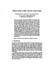
1 Introduction In this paper, we consider the problem of determining the position of a mobile robot with respect to a known frame of reference by comparing a range map computed from a stereo pair of images taken at the robot's current location to a range map from a previous location or to a composite range map of the environment that has been previously generated. Our motivation for studying this problem is to increase the autonomy of the Rocky 7 Mars rover [14]. See Figure 1. While the position of the rover is continuously updated through dead-reckoning using wheel encoders and an angular-rate sensor, wheel slippage and sensor drift cause an accumulation of error in this estimated position [8]. It is thus desirable to have additional means for periodically localizing the rover to correct this accumulated error. Previous techniques that have been used to localize Rocky 7 have concentrated on imaging the rover from the lander that will carry the rover to the Mars surface [15]. However, this limits the operable range of the rover to a small area around the lander. To enable operation of the rover at distances far from the lander, autonomous localiza-
Figure 1: The Rocky 7 Mars rover prototype.
tion procedures are necessary and we consider the use of stereo vision for this problem here. A mast system has been integrated into Rocky 7 that allows (among other operations) stereo pairs to be taken from a height of approximately 1.5 meters above the ground, in addition to the stereo pairs that are taken by the navigation cameras close to the ground. See Figure 2. Such stereo pairs allow the generation of a range map of the immediate surroundings of the robot. The premise of this work is that we can robustly determine the position of the robot in natural terrain using iconic matching techniques by comparing this range map computed at the robot's local position with a range map encompassing the same terrain for which we know the frame of reference. While other research has also performed matching of maps to perform localization and/or terrain modeling (e.g. [1, 2, 6, 10]), previous iconic matching methods require an initial estimate of the robot's position and use iterative re nement techniques that can reach a sub-optimal local minima. The techniques that we describe here can operate in a natural environment using a three-dimensional map, they are guaranteed to nd the globally optimal solution with respect to the matching measure that we use, without requiring
c 1997 IEEE. Personal use of this material is permitted. However, permission to reprint/republish this material for advertising or promotional purposes or for creating new collective works for resale or redistribution to servers or lists, or to reuse any copyrighted component of this work in other works must be obtained from the IEEE.
warped to remove the lens distortion and the images are recti ed so that the corresponding scan-lines yield corresponding epipolar lines in the image. The image disparity at each pixel is measured by minimizing the sum-of-squared-di�erence (SSD) measure of a window around the pixel over a nite disparity range. Subpixel disparity estimates are computed using parabolic interpolation. Smoothing is performed over a 3�3 window to reduce noise. Incorrect matches are ltered out in this process using both a left-right-line-of-sight consistency check and a process to remove small patches where the disparities do not agree with surrounding values. Given the disparities, the coordinates of each pixel are computed by triangulation. Details of these techniques can be found in [7, 9]. Once a range map has been computed from the stereo imagery, we convert it into a voxel-based map representation. We rst rotate the data such that it has the same relative orientation as the map we are comparing it to. Here we operate under the assumption that the orientation of the robot is known through sensors other than vision (for example, a sun sensor, accelerometer, and gyrocompass have been incorporated into Rocky 7). For testing, and in case the accuracy of the sensors is lower than desired, we have used a simple technique for determining the orientation of the ground plane, assuming that the ground is relatively at. This technique simply determines the two principal components of the range points that are detected in the image and rotates them such that they are parallel to the xy-plane. The next step is to bin the range points in a twodimensional grid covering the xy-plane at some speci ed scale. We approximate the terrain as a singlevalued function of the position in the xy-plane (i.e. z = f (x; y)). We thus take the average of the heights of the range points that fall into each of the bins as the height of the surface at this location. Now, we can eliminate the need to search over the possible translations of the robot in the z -direction by subtracting a local average of the terrain height from each cell (i.e. a high-pass lter). This step is not strictly necessary, and it reduces our ability to determine height changes in the position of the robot, but it also reduces the computation time that is required to perform localization. Finally, we perform smoothing on this twodimensional grid. This smoothing allows small areas that were not hit by any range pixel (e.g. due to sparseness of the range pixels) to be given values, but does not ll in large areas (such as range shadows). The un lled pixels do not otherwise contribute to the smoothing. To facilitate matching using a Hausdor� measure,
Figure 2: Rocky 7 with the mast deployed.
an initial estimate of the robot position, and they are computationally e�cient. The balance of the paper explores these ideas in greater detail. Section 2 discusses the process by which the range maps of the robot's surroundings are computed and describes the techniques that we use to transform these range maps into a voxel representation that allows robust and e�cient matching. Section 3 discusses our use of Hausdor� matching techniques [4, 5, 11, 13] to nd the relative position between the maps such that the maximum number of voxels are matched up to a given error bound. Section 4 describes results that have been obtained using this method. Finally, Section 5 summarizes this work.
2 Computing range maps We compute range maps from image pairs using passive stereo vision [7]. It is assumed that the robot cameras have been calibrated o�-line. Rocky 7 uses a camera model that allows arbitrary a�ne transformations of the image plane [16] and that has been extended to include radial lens distortion [3]. The images are rst 448
(a)
(b)
(c)
Figure 3: Range maps are computed using stereo vision. (a) Left image of a stereo pair. (b) Height of pixels determined using stereo triangulation. (Black pixels indicate no data.) (c) Surface extracted from the pixel heights.
we transform this two-dimensional map into a threedimensional occupancy map, where the z -axis is discretized at the same scale as the x- and y-axes. For each column in the map, the cell corresponding to the height of the surface at this (x; y)-position is said to be occupied, and the others are said to be unoccupied. Figure 3 shows intermediate steps of this process.
at least a small fraction of outliers that do not match well. We thus use the partial Hausdor� distance [4]: th min jja ? bjj hK (A; B ) = K a2A b2B
This measures the Hausdor� distance among the K points in A that best match points in B (we thus allow jAj ? K outliers in the set A). This measure is asymmetric, as it does not consider how well each of the points in B is t by A. This allows matching to be performed against a large global map, where the map generated at the local robot position is contained as a subset of the global map. A variation on this measure is to determine the maximum number of points, K , such that the measure is below a given error threshold: hK (A; B ) � �
3 Matching range maps Once the occupancy map has been computed for the current position of the robot, we need to nd the best relative position between this map and a map for which we know the frame of reference (which we call the global map). For example, we may compare against the map for a previous position of the robot, or a composite map that has been generated for the robot's operating environment (possibly through combining maps taken from the robot's previous locations). Alternatively, this map may be generated from descent or orbital imagery or from an image panorama from the rover or lander. To perform this matching, we use an image matching technique based on the Hausdor� distance [4].
This formulation is easy to work with, since, to compute this number, we must only count the number of points in A that match some point in B up to the error, � . We thus use this formulation in this work.
3.2 Search strategy
3.1 The Hausdor� distance
While previous Hausdor� matching methods [4, 5, 11, 13] have been applied to matching two-dimensional image edge maps, we can apply similar techniques to the matching of three-dimensional image surface maps. In this method, each occupied cell in the maps is represented by the single point at the center of the cell. The space of possible relative positions between the maps is also discretized. Since we search over only translation in the x- and y-directions, an obvious discretization exists such that each discrete position
For two sets of points, A and B , the directed Hausdor� distance from A to B is: h(A; B ) = max min jja ? bjj ; a2A b2B
where jj�jj is any norm. This yields the maximum distance from a point in set A to the nearest point in set B . However, this is not robust to outliers in A or missing points in B . For image matching, we wish to allow 449
aligns the centers of various grid cells between the two maps (assuming that the maps have the same scale). This discretization is guaranteed to nd the optimal solution if we use the l1 or l1 norm in our matching measure with an error, � , that is an integral number of pixels. We could now examine each possible relative position between the maps in this discretization to determine which is optimal, but this method would be computationally expensive. We instead use a multiresolution search technique that has proven useful in object recognition applications [5, 11, 13]. The basic idea is to consider the space of possible relative positions as a set of rectilinear cells, each of which covers many positions. Each cell is tested to determine whether it could contain a position that satis es some matching criterion. If it is determined that the cell cannot contain such a position, then it is pruned. Otherwise, the cell is divided into subcells and the process is repeated recursively. When a cell is reached that contains a single position in the discretization, this position is tested explicitly. Note that, since we are seeking the single best relative position between the maps, our matching criterion is adaptive. The criterion becomes stricter as we nd positions of increasing quality in the search.
a two-pass algorithm [12]. Now, a probe into the distance transform of our dilated map yields zero if the cell is within � of an occupied cell in the undilated map, and otherwise yields the distance to the closest occupied cell in the dilated map. Consider the set of distances, fd1 ; :::; dng, that are obtained by probing the distance transform at the position of each of the occupied cells in the robot's local map with respect to some relative position between the maps. If this set has K zero values, then at least K cells in the local map are within � of occupied cells in the global map. Otherwise, the K th largest value in the set yields a bound on the distance from the examined relative position to a position that could yield K zero values [4]. We can use these ideas to formulate an e�cient test for a cell in the parameter space in the following manner. Let us say that the best position that has been found so far yields B cells in the local map that match the global map up to the allowed error (i.e. B probes into the distance transform for this position yield zero). To test a cell, we rst determine the discrete position closest to the center of the parameter space cell. We then determine the distance between this position and the furthest corner of the cell. Denote this distance Dc . This is the maximum distance between the location that the center position maps a local voxel into the global map and the location any other position in the cell maps the same voxel. We now probe the distance transform at the locations of the occupied pixels in the local map with respect to the relative position at the center of the cell. If these probes, fd1; :::; dng, yield no more than B values that are not greater than Dc , then we can prune this cell of the parameter space, since it cannot yield a position at which more than B cells in the local map match occupied cells in the global map up to an error of � . Our test is thus whether the following expression is satis ed: n � X 1; if di � Dc B� 0 i=1 ; otherwise
3.3 Pruning mechanism The key to this method of searching the parameter space is a fast method to conservatively test whether a cell can contain a position satisfying the matching criterion. The test can fail to rule out a cell that does not contain such a position, but it should never rule out a cell that does contain one. To accomplish this, we examine a distance transform [12] of the global occupancy map. First, the occupancy map is dilated with a cubic structuring element centered at the origin that has 2� + 1 pixels on each edge. This operation ensures that each cell within � in each direction of an occupied cell in the original map is also occupied. Next, a distance transform of this map is computed. This distance transform measures the distance from each cell in the map to the closest occupied cell that lies in the same horizontal plane (since we search only in x and y). Let M be the set of occupied pixels in a map. The distance transform of the map can be de ned as follows: DM (X) = min jjX ? Yjj
For any cell that cannot be pruned, we divide the cell into subcells of approximately the same size by dividing along each axis and repeat the process recursively on these subcells. When a cell is reached that contains a single position in the discretized pose space, we test this position explicitly. If the position yields more than B matches, then we store this position as the best found so far, increase B to the new value, and resume the search. This continues until all of the cells have been exhausted, at which point we are guaranteed to have found the best relative position between
Y2M
We are interested in the digital distance transform of the map, and this can be computed e�ciently using 450
Figure 4: A sequence of images used for testing the localization techniques.
than 5 was thus achieved through the use of the e�cient search techniques. While these tests were performed on a workstation, the code has recently been ported to the Rocky 7 hardware for full testing. Both implementations require only a few seconds to perform all of the computation, including stereo triangulation.
the maps according to the variation of the Hausdor� measure that we use.
4 Results We have tested these techniques with images taken in the JPL Mars Yard1 using cameras mounted on a tripod at approximately the Rocky 7 mast height. Figure 4 shows a set of images that was used in testing the localization techniques. The set consists of 12 stereo pairs acquired at one meter intervals along a straight line with approximately the same heading. In these tests, we determined the estimated position changes by nding the relative position between each pair of consecutive images. These relative positions were determined by matching occupancy maps created as described above. The localization techniques yielded a qualitatively correct position between each pair of consecutive images. The average absolute error in the position estimates was 0.0342 meters in the downrange direction and 0.0367 meters in the crossrange direction from the position measured by hand. It is likely that further accuracy could be obtained by using this position as the starting position for an iterative hill-climbing technique. Additional tests were performed on imagery where the camera system was panned 25 degrees left and right. Figure 5 shows an example. In these tests, occupancy maps from the panned images were matched to occupancy maps for the unpanned images. All 24 trials yielded the correct qualitative result. The average absolute error was 0.0138 meters in the downrange direction and 0.0225 meters in the crossrange direction. In these tests, the average number of positions examined was 18.45% of the total number of positions in the discretized search space. A speedup of greater 1
5 Summary This paper has considered self-localization techniques for a mobile robot in natural terrain through the use of stereo vision. The robot's position is determined by comparing a terrain map computed at the robot's current location to a terrain map in a known frame of reference. We rst generate a dense range map from stereo imagery and then process this data to create an occupancy map of the terrain surface. The best relative position between this occupancy map and the occupancy map in the known frame of reference is determined with respect to a Hausdor� measure using iconic matching techniques. The optimal position is found using a search strategy that recursively divides and prunes the space of possible relative positions. This yields a method that is robust to noise, scene clutter, and missing data. Unlike previous iconic matching techniques for comparing range maps, this technique does not require an initial estimate of the position of the robot, and the globally optimal position of the robot is found with respect to the matching measure that is used.
Acknowledgments The author thanks Bob Balaram and Larry Matthies for insightful discussions on this topic, Todd Litwin who developed the camera calibration and stereo code, and Sharon Laubach who acquired the test data.
See http://robotics.jpl.nasa.gov/tasks/scirover/marsyard
451
(a)
(b)
(c)
Figure 5: Test case with rotation. (a) Position 10 with heading -25 degrees. (b) Position 10 with heading straight ahead. (c) Position 10 with heading +25 degrees.
The research described in this paper was carried out by the Jet Propulsion Laboratory, California Institute of Technology, under a contract with the National Aeronautics and Space Administration.
[8] L. Matthies, E. Gat, R. Harrison, B. Wilcox, R. Volpe, and T. Litwin. Mars microrover navigation: Performance evaluation and enhancement. Autonomous Robots, 2(4):291{312, 1995. [9] L. Matthies, A. Kelly, T. Litwin, and G. Tharp. Obstacle detection for unmanned ground vehicles: A progress report. In Proceedings of the International Symposium on Robotics Research, 475-486, 1996. [10] F. Nashashibi, M. Devy, and P. Fillatreau. Indoor scene terrain modeling using multiple range image for autonomous mobile robots. In Proceedings, IEEE Conference on Robotics and Automation, 40{46, 1992. [11] C. F. Olson and D. P. Huttenlocher. Automatic target recognition by matching oriented edge pixels. IEEE Transactions on Image Processing, 6(1):103{113, January 1997. [12] A. Rosenfeld and J. Pfaltz. Sequential operations in digital picture processing. Journal of the ACM, 13:471{494, 1966. [13] W. J. Rucklidge. Locating objects using the Hausdor� distance. In Proceedings of the International Conference on Computer Vision, 457{464, 1995. [14] R. Volpe, J. Balaram, T. Ohm, and R. Ivlev. The Rocky 7 Mars rover prototype. Proc. IEEE/RSJ Intl. Conf. on Intelligent Robots and Systems, vol. 3, 1558{ 1564, 1996. [15] R. Volpe, T. Litwin, and L. Matthies. Mobile robot localization by remote viewing of a colored cylinder. Proc. IEEE/RSJ Intl. Conference on Intelligent Robots and Systems, vol. 1, 257{263, 1995. [16] Y. Yakimovsky and R. Cunningham. A system for extracting three-dimensional measurements from a stereo pair of TV cameras. Computer Vision, Graphics, and Image Processing, 7:195{210, 1978.
References [1] A. Elfes. Sonar-based real-world mapping and navigation. IEEE Journal of Robotics and Automation, 3(3):249{265, June 1987. [2] D. B. Gennery. Visual terrain matching for a Mars rover. In Proceedings of the IEEE Conference on Computer Vision and Pattern Recognition, 483{491, 1989. [3] D. B. Gennery. Camera calibration including lens distortion. JPL internal report D-8580, Jet Propulsion Laboratory, California Institute of Technology, 1991. To appear in Calibration and Orientation of Cameras in Computer Vision, A. Grun and T. S. Huang, eds. [4] D. P. Huttenlocher, G. A. Klanderman, and W. J. Rucklidge. Comparing images using the Hausdor� distance. IEEE Transactions on Pattern Analysis and Machine Intelligence, 15(9):850{863, September 1993. [5] D. P. Huttenlocher and W. J. Rucklidge. A multiresolution technique for comparing images using the Hausdor� distance. Proc. IEEE Conference on Computer Vision and Pattern Recognition, 705{706, 1993. [6] I. S. Kweon and T. Kanade. High-resolution terrain map from multiple sensor data. IEEE Transactions on Pattern Analysis and Machine Intelligence, 14(2):278{ 292, February 1992. [7] L. Matthies. Stereo vision for planetary rovers: Stochastic modeling to near real-time implementation. International Journal of Computer Vision, 8(1):71{ 91, July 1992.
452