Apr 4, 2012 - A load balancing problem occurs when some service cells have ... The mobility and resource management of 3G LTE systems should support the load ... condition change of a cell is caused not only by handover calls but also ...
Qi-Ping Yang et al. / International Journal on Computer Science and Engineering (IJCSE)
Mobility Prediction and Load Balancing Based Adaptive Handovers for LTE Systems Qi-Ping Yang, Jae-Woo Kim, Tae-Hyong Kim Department of Computer Engineering Kumoh National Institute of Technology Gumi, Republic of Korea {qpyang, eva0191, taehyong*}@kumoh.ac.kr, *corresponding author
Abstract—In cellular networks including Long Term Evolution (LTE) systems, how to balance the load is indispensable because traffic load and local user densities vary dynamically. A load balancing problem occurs when available wireless resources are not enough to support the requirements of users. Such a problem may lead to blocked or dropped calls and degrade the quality of service. This paper proposes a mobility technique with adaptive handovers based on load balancing. In the proposed technique, a heavy loaded cell adaptively configures handover hysteresis threshold differently for each neighboring cell according to the load information of that neighboring cell. A simple prediction technique is also used for reducing the number of unnecessary handovers that may arise from load balancing. In the simulation results, the proposed technique shows lower blocking and drop rates for new and handover calls, which reveals its enhancement of the resources utilization and the service quality for LTE systems. Keywords: LTE system, load balancing, mobility prediction, adaptive handover I.
INTRODUCTION
A The third generation partnership project (3GPP) started the project, long-term evolution (LTE) of the third generation (3G) mobile communication systems, to ensure competitiveness in terms of both performance and cost in 2004 [1]. This project should provide various multi-services and guarantee the quality of services (QoS) with high data rates. The LTE allows many-to-many interface between enhanced NodeBs (eNodeB) and core network nodes (access gateways, aGW), called S1-flex. The pool area concept is also introduced such that a UE can be served by more than one mobility management entity (MME) / user plane entity (UPE) in parallel and pool areas are also allowed to overlap [2]. Those novel features should be considered in the 3G LTE system management such as mobility and resource management. A load balancing problem occurs when some service cells have insufficient resources to satisfy the demands of users while their neighbor cells still have enough resources to accept new calls. Obviously, this problem degrades the QoS in the heavy load cells because it causes a high blocking probability of new calls or handover calls. The problem also decreases the efficiency of resource utilization since the available resources in the neighbor cells are not used. The mobility and resource management of 3G LTE systems should support the load balancing by considering various new situations due to the S1¬flex interface and the pool area concept. Two general methods, channel borrowing [3] and load distributing [4-5], have been widely used to solve the load balancing problem. In the load balancing based on channel borrowing, overloaded cells try to borrow required resources from neighboring light loaded cells. The channel borrowing schemes are not applicable or inefficient to 3G LTE systems because the channel reuse factor of 3G LTE systems is 1 because of its orthogonal frequency division multiple access (OFDMA) technology. Load distributing algorithms attempt to distribute the traffic load of the heavy loaded cells by controlling the transmitting power of the base station or forcing some mobile stations to handover to neighboring light loaded cells. Load distribution is better for 3G LTE systems since controlling the transmitting power of the base station may bring excessive interference to mobile nodes. Lately, as a load distributing algorithm, [5] proposes the adaptive handover time scheme to dynamically control the handover time according to the load status of cells. In this scheme, handovers to heavy loaded cell are delayed with slow handover time algorithm and the heavy loaded cells execute possible handovers early with fast handover time algorithm. This scheme increases the number of unnecessary handovers when it executes fast handover, and also need extra signaling to exchange load information between cells in every handover. Moreover, this scheme will delay or block the handover if the target cell is in heavy load status. Therefore, we need a mobility management technique suitable for 3G LTE systems to solve the load balancing
ISSN : 0975-3397
Vol. 4 No. 04 April 2012
638
Qi-Ping Yang et al. / International Journal on Computer Science and Engineering (IJCSE)
problem. This paper proposes a mobility management technique to solve the load balancing problem using adaptive handovers. In the proposed approach, a heavy loaded cell dynamically configures different handover hysteresis thresholds for each neighboring cell according the load information of the neighboring cells. The proposed technique also uses a prediction technique to reduce unnecessary handovers. Various handover conditions according to the S1-flex and pool area concept are also considered in the proposed technique. The rest of this paper is organized as follows. The next section describes the proposed technique in detail. Section 3 presents the simulation model and results of the proposed technique. Finally, we draw our conclusions in section 4. II.
ADAPTIVE HANDOVERS WITH LOAD BALANCING
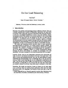
A. Load Balancing Algorithm We present a mobility management technique with adaptive handovers based on load balancing for 3G LTE systems. An adaptive handover means that the handover hysteresis thresholds are dynamically updated according to the load conditions of cells. In the conventional handover mechanism, handover decision only depends on degradation of the received signal strength (RSS) of the base station and the hysteresis threshold value is fixed. It does not consider the load status of the current serving cell and the target cell. The proposed method executes a handover to the best cell for the user with guaranteed high service quality by considering both signal strength and load information. This method is also expected not to increase the system’s complexity because it only considers the handover hysteresis thresholds without changing the structure of the system itself. Figure 1 shows the outline flow of the proposed adaptive handover based on load balancing. The proposed technique triggers the load balancing procedure according to the load condition change of each cell. The load condition change of a cell is caused not only by handover calls but also by new calls or resource reconfiguration. If a cell does not have enough remaining resources, it will ask the load balancing procedure that forces some user equipments (UE’s) to handover to the neighboring cells. Accordingly that heavy loaded cell adaptively balances the load to its neighboring light loaded cells. In this approach, we also consider the situation of multiple MME’s. As a last resort, the handover to other MME’s cell is allowed, which process will take more time due to MME change.
Figure 1. The proposed adaptive handover concept.
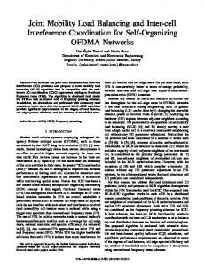
The following notations are used to describe the proposed load balancing technique: the amount of available resources vAR(i) and the amount of total resources vTR(i) for cell i (i=0 means the current serving cell). The ratio of these two values is used for comparison with the predefined thresholds to decide whether the current cell needs load balancing or not. The load balancing algorithm is triggered and terminated by the predefined thresholds ThPre_LB and Thpost_LB, respectively. The threshold Thavail_LB indicates the condition for admitting load balancing. Figure 2 shows the relations of these parameters. If the amount of available resources per the total amount of resources of the current cell is less than the threshold ThPre_LB, i.e., vAR(0)/vTR(0)ThHys(0,j), UE l executes handover from the current cell to cell j. This load balancing procedure is shown in Figure 3. In this figure, the symbols ‘*’ and ‘**’ denote the messages including the new handover hysteresis thresholds which are different from the original messages. Here, we point out that these new messages and multiple handover hysteresis thresholds for the load balancing algorithm may need more resources. But the bandwidth required for that additional threshold management is extremely small when compared with that required for user data service. According to this fact, we assume that each cell can perform this procedure with negligible overhead. As shown in figure 3, the load balancing procedure is terminated when the available resources per total resources of the cell reaches the termination threshold, i.e., vAR(0)/vTR(0)>ThPost_LB. If the cell satisfies this condition, the load of the cell is considered light enough and the cell should restore the handover hysteresis threshold to the original value by sending another measurement control message to its served UE’s. The adaptive handover possibly increases the number of ping-pong handovers because some handovers may be executed prematurely when the handover hysteresis thresholds is reduced. Figure 4 shows an example of unnecessary handovers. In that figure, the cell1 expands its handover area from the original boundary to a new boundary by reducing its handover hysteresis threshold for cell2 when it executes load balancing. Suppose that cell1 is the serving cell of UE1 and UE2 and both UE’s are located in the newly expanded handover area. Then UE1 and UE2 may perform handovers to cell2 and release their resources for solving the load balancing problem of cell1. However, if we assume UE2 is moving from cell2 to cell1, UE2 will experience another handover from cell2 to cell1 when UE2 enters the handover area of cell2. If the time interval between these two handovers of UE2 is very short, UE2 have executed unnecessary handovers and the performance of load balancing is reduced. For solving this problem, the optional function named DirPred(l) in figure 3 is used. A lot of prediction techniques have been used to estimate handovers for fast and seamless handover. In our method, we use the prediction technique proposed in [8] to simply decide whether the target cell is the best handover cell
ISSN : 0975-3397
Vol. 4 No. 04 April 2012
640
Qi-Ping Yang et al. / International Journal on Computer Science and Engineering (IJCSE)
of the UE. One of the following two prediction policies is used. In prediction policy I, a UE executes a handover only when the target cell is the best handover cell. In prediction policy II, some UE’s may execute handovers even if their target cells are not the best handover cells, if the number of UE’s for adaptive handovers is not enough for load balancing.
Load Condition Changed
No
RSSl(j)-RSSl(0) > ThHys(0,j)? Yes No
vAR(0)/vTR(0) < ThPre_LB?
NOK DirPred(l)? Option
Yes
OK
ThHys(0,i)← New_thres(i), for each i (1≤i≤n)
Execute Handover of UE l to Cell j
Msrm. Control* to all UE’s for Setting new ThHys
No
vAR(0)/vTR(0) > ThPost_LB? Yes
Msrm. Report(1D)** from UE l ( for HO To Cell j (1≤j≤n) )
Msrm. Control* to all UE’s for Setting original ThHys
Figure 3. The proposed load balancing algorithm.
cell1 original handover area UE2
Cell2
Cell1 cell1 new handover area
UE1
cell1 new handover to cell2 boundary Cell2 drop Cell2 handover to cell1 boundary boundary
cell1 original handover to cell2 boundary
cell1 drop boundary
Figure 4. An example of unnecessary handovers.
B. Handover Procedure In 3G LTE systems, the load information management should be performed by the radio resource management (RRM). This RRM function can be located in a primary access gateway (aGW) or a master eNodeB in a centralized manner, or in each eNodeB in a distributed manner. Actually the location of this function is not so important because load information and signaling cost is not so much for both centralized and distributed management [6]. Figure 5 shows the proposed adaptive handover sketch based on load information exchange which can be applied to 3G LTE systems. We use a common RRM (CRRM) [7] located in the aGW to manage the load information. When the load status of an eNodeB is changed, that eNodeB updates the load information to the CRRM. If the heavy load condition is satisfied at an eNodeB, it sends a load information request message to the aGW and takes its neighboring cells’ load information by receiving a load information response messages from the aGW. According to the received load information, the eNodeB updates its handover hysteresis thresholds, and then executes an adaptive handover process for load balancing until its load status returns to the light load condition.
ISSN : 0975-3397
Vol. 4 No. 04 April 2012
641
Qi-Ping Yang et al. / International Journal on Computer Science and Engineering (IJCSE)
UE
aGW (CRRM)
eNodeB
1. Update Load Information 2. Heavy Load Condition 3. Load Information Request 4. Load Information Response
5. Update ThHys(0,i)
6. Handovers due to Load Balancing
Figure 5. An example of unnecessary handovers.
III.
SIMULATION
We designed and implemented the proposed mobility management system in the specification and description language (SDL), a formal description technique [9]. In order to show the improvement of our load balancing algorithm, we designed three simulation systems: a system without load balancing, a system only with load balancing, and a system with load balancing using UE’s movement prediction. The implementation of the prediction technique includes both prediction policies I (prediction I) and II (prediction II). The following five performance parameters are used to examine the performance of the proposed technique.
Handover call blocking rate: the number of blocked handover calls per the total number of handover calls.
Handover call drop rate: the number of dropped handover calls per the total number of handover calls.
New call blocking rate: the number of blocked calls per the total number of new calls.
Handover number: the number of handover calls.
Ping-pong handover rate: the number of unnecessary handover calls per the total number of handover calls.
A. Simulation Models
Overlapping Area
Pool Area A Pool Area B 16 Environment cells for prediction
mobility zone (5 cells) Pool Area B boundary
Pool Area A boundary
Figure 6. The simulation model of the cellular layout.
The simulation model of the cellular network area consists of 21 macro cells distributed in two pool areas with the same radius of 1km as shown in figure 6. In that figure five cells numbered from 1 to 5 are the mobility zone within which UE’s can move around. 16 environment cells are assumed to be always in the light load
ISSN : 0975-3397
Vol. 4 No. 04 April 2012
642
Qi-Ping Yang et al. / International Journal on Computer Science and Engineering (IJCSE)
condition in order to support the prediction technique. Various parameters for the simulation are described in table I. As shown in that table, we allow at most 250 UE’s in the simulation area. The traffic of each UE follows the Erlang distribution as shown in figure 7. The ratio of active time to idle time is 6:1 for generating heavy loaded cells during the simulation. The mobility pattern of each UE is the random way point model, where the movement direction in degree is generated by the uniform distribution of the range [0, 360). At each linear path, the speed of UE changes as follows: 0.3x(010%), 0.5x(10-20%), x(20-80%), 0.5x(80-90), and 0.3x(90100%), where x is the full speed and the range in each parenthesis indicates the section of the path. We designed three simulation scenarios as shown in Table II.
Active time : Erlang (mean :1200s) Idle time: Erlang (mean: 200s) PRB value: Erlang (mean: 3~8)
Traffic (PRB)
Active time t A(2) Prb(2)
Active time t A(3)
Active time t A(1)
Prb(1)
……
Time (s)
Idle time t I(2)
Idle time t I(1)
Figure 7. The traffic model for the simulation. TABLE I.
THE SIMULATION PARAMETERS
Parameters
Values
Pool Area Number Cell Number Cell Diameter Cell Capacity UE Number UE Mobility UE Speed UE Active Time UE Idle Time Traffic Model Normal Handover Threshold Dynamic Handover Threshold ThPre_LB ThAvail_LB ThPost_LB Simulation Time
2 21 1000 m 30~130 PRBs 0~250 Random waypoint 0~100km/h Erlang distribution (mean: 1200s) Erlang distribution (mean: 200s) Erlang distribution (mean: 3~8 PRBs) 5 dB 0~5 dB 0.2 0.3 0.4 10 hours
TABLE II.
Cell Capacity (PRB) UE Number Traffic Mean (PRB)
THE SIMULATION SCENARIOS Scenario I
Scenario II
Scenario III
60 100~250 6
30~130 200 6
60 200 3~8
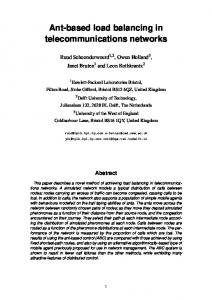
B. Simulation Results The number of heavy loaded cells increases when the number of UE’s is increased, when the cell capacity is reduced, or when the traffic mean is increased. Since the results of each scenario were similar, we only show the results of simulation scenario I. As for the handover call blocking rate, the proposed technique without prediction is about 15% better than that of the conventional handover when the UE number is increased to 250 as show in figure 8. In this figure, the handover call blocking rate with prediction I is about 4% higher than that of the proposed method without prediction because some UE’s are prevented from adaptive handovers for load balancing by the movement prediction. But the result of prediction II is very close to the proposed method without prediction because that prediction policy does not give up adaptive handovers until the termination condition for load balancing is
ISSN : 0975-3397
Vol. 4 No. 04 April 2012
643
Qi-Ping Yang et al. / International Journal on Computer Science and Engineering (IJCSE)
H/O blocking rate
satisfied. The rate of handover call drop and the rate of new call blocking show similar results. In figures 10 and 11, when the number of UE’s is increased, the blocking rate was also increased as expected. As can be seen in Figure 11, due to the additional adaptive handovers for load balancing, the number of handovers in the proposed method is slightly higher than that without load balancing, which is one of the costs of the proposed method for more efficient resource management. Figure 12 shows the rate of ping-pong handovers. As we mentioned, the proposed technique without prediction shows higher rate of ping-pong handovers by 6% than that of without load balancing at the heaviest load situation. The prediction technique decreases the rate of ping-pong handovers as expected. This result shows that the prediction technique is useful to reduce unnecessary handovers. That figure also shows that prediction II is not as efficient as prediction I because UE’s execute handovers in the end if the heavy load situation is not resolved. 0.3 0.25 W/O LB 0.2
With LB
0.15
With LB+Predication I
0.1
With LB+Predication II
0.05 0 100
120
140
160
180
200
220
240
UE number
H/O drop rate
Figure 8. The handover call blocking rate.
0.01 0.009 0.008 0.007 0.006 0.005 0.004 0.003 0.002 0.001 0
W/O LB With LB With LB+Predication I With LB+Predication II
100
120
140
160
180
200
220
240
UE number
call blocking rate
Figure 9. The handover call drop rate.
0.3 0.25
W/O LB
0.2
With LB With LB+Predication I
0.15
With LB+Predication II
0.1 0.05 0 100
120
140
160
180
200
220
240
UE number Figure 10. The new call blocking rate.
ISSN : 0975-3397
Vol. 4 No. 04 April 2012
644
H/O number
Qi-Ping Yang et al. / International Journal on Computer Science and Engineering (IJCSE)
55000 50000
W/O LB
45000 With LB
40000 35000
With LB+Predication I
30000
With LB+Predication II
25000 20000 15000 100
120
140
160
180
200
220
240
UE number
pingpong handover rate
Figure 11. The handover number.
0.09 0.08
W/O LB
0.07
With LB
0.06 0.05
With LB+Predication I
0.04
With LB+Predication II
0.03 0.02 0.01 0 100
120
140
160
180
200
220
240
UE number Figure 12. The ping-pong handover rate.
IV.
CONCULDING REMARKS
This paper proposed a mobility management technique with adaptive handovers based on sophisticated load balancing for 3G LTE systems. In the proposed method, a heavy loaded cell dynamically configures the handover hysteresis threshold differently for each neighboring cell according to the load information of that neighboring cell. The proposed method also uses a prediction technique to reduce the unnecessary handovers due to load balancing. The simulation results show that it can increase the efficiency of resources utilization and enhance the quality of service in the 3G LTE systems. As future work, we will develop better prediction techniques in order to select UE’s for adaptive handovers intelligently. The detailed comparison with other load balancing techniques is also in progress for refining the proposed technique. ACKNOWLEDGMENT This paper was supported by Research Fund, Kumoh National Institute of Technology. REFERENCES [1] [2] [3] [4]
[5] [6] [7] [8] [9]
3GPP TD RP-040461: Proposed Study Item on Evolved UTRA and UTRAN, 2004. TD R3-061617: LS on Definition of Pool Area for LTE, 3GPP TSG-RAN WG3 Meeting #53bis, Seoul, Korea, 2006. H.Jiang and S.S. Rappaport. “CBWL: A new channel assignment and sharing method for cellular communication systems,” IEEE Transactions on Vehicular Technology 43(2). 1994. Steuer, J. and K. Jobmann. “The use of mobile positioning supported traffic density measurements to assist load balancing methods based on adaptive cell sizing,” in Personal, Indoor and Mobile Radio Communications. The 13th IEEE International Symposium on. 2002. Dongwook, K., S. Mrinalini, and Y. Hyunsoo, “An effective traffic management scheme using adaptive handover time in nextgeneration cellular networks, ”2007, John Wiley \& Sons, Inc. p. 139-154. 3GPP, TR R3.018, Radio Access Architecture and Interfaces (Release 7), V0.5.0, 2006,9. Tolli, A., P. Hakalin, and H. Holma. “Performance evaluation of common radio resource management (CRRM),” in Communications, 2002. IEEE International Conference on. 2002. Kim, T.-H., et al. “A Mobility Management Technique with Simple Handover Prediction for 3G LTE Systems.” in Vehicular Technology Conference, 2007. VTC-2007 Fall. 2007 IEEE 66th. 2007. ITU Recommendation Z.100, Specification and Descritption Language (SDL). ITU, Geneva, 1999.
ISSN : 0975-3397
Vol. 4 No. 04 April 2012
645
Qi-Ping Yang et al. / International Journal on Computer Science and Engineering (IJCSE)
AUTHORS PROFILE
QI-PING YANG received the B.S. degree in communication engineering from Jilin University, Changchun, China, in 2001, and the M.S. and Ph.D degrees in computer engineering from Kumoh National Institute of Technology (KIT), Korea, in 2006 and 2012, respectively. His research areas of interest are software testing techniques and next generation mobile networks. JAE-WOO KIM received the B.S. degree in computer and software engineering from Kumoh National Institute of Technology (KIT), Korea, in 2004, and the M.S. degree in computer engineering from the same university in 2006. He is currently a Ph.D. candidate in the School of Computer and Software Engineering at KIT. His research areas of interest are protocol engineering and next generation mobile networks. TAE-HYONG KIM received the B.S. and M.S. degrees, from Yonsei University in 1992 and 1995, respectively, and a Ph.D. degree in electrical and electronic engineering from the same university in 2001. He was a postdoctoral fellow at the School of Information Technology and Engineering (SITE) at the University of Ottawa from 2001 to 2002. He is currently an associate professor in the department of computer engineering at the Kumoh National Institute of Technology (KIT) in Korea His research areas of interest are software and protocol specification, verification and testing techniques, communication protocols, and next generation mobile networks.
ISSN : 0975-3397
Vol. 4 No. 04 April 2012
646