Model-Based Design: Experiences from Valve Controller Development
Mats Friman Metso Flow Control, P.O.Box 306, FI-33101 Tampere, Finland Tel: +358 40 7720857, E-mail
[email protected] KEY WORDS model-based design, valve controllers, simulation
ABSTRACT This paper discusses model-based design, which is a control design method that utilizes simulation. We present some experiences from adopting model-based design in a real product development project, the development of the Neles NDX valve controller. There are many advantages with model-based design, most notably more efficient development, improved quality, and cost savings. We assess our experience of such advantages and we discuss some examples.
1 INTRODUCTION Today, process industry plants are efficient and highly automated, driven by optimization engines and thousands of control loops. Every second, an automation system produces hundreds of decisions, which are implemented by so called final control elements. The most common final control element in the process industry is the control valve. The control valves manipulate flows in pipelines, indirectly controlling various variables, like pressure, level, temperature, concentration and other quality variables. A control valve package consists of a valve body, a pneumatically powered actuator, and a valve positioner. The main tasks of the valve positioner are to receive the valve opening setpoint from the automation system, to measure the valve position and to control valve position according to the provided valve setpoint (Kirmanen et al., 1997). Today, most valve positioners are digital devices, i.e. embedded systems with complex control algorithms and complex features that exemplify modern technology and latest innovations. The best positioners are equipped with many useful features, including automatic calibration and tuning, on-line diagnostics, self-testing routines, and a local user interface for easy commissioning and manual operation. Utilizing digital communication standards, remote operation of positioners is fully supported. In this paper we discuss some experiences of using model-based design in the product development project of Neles NDX valve controller. Neles NDX is the latest valve controller from Metso.
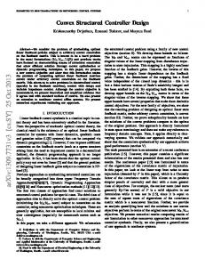
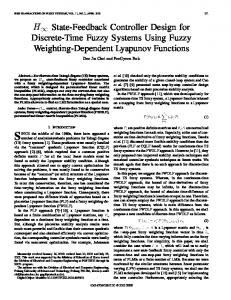
2 CHALLENGES OF CONTROL ALGORITHM DEVELOPMENT A feedback control loop is illustrated in Figure 1. Designing embedded software for feedback control is different compared to many other software development projects. As an example, consider a simple P controller u = KC(r-y) + ub
(1)
where r is setpoint of the controlled variable, y is measured value of the controlled variable, KC is controller gain, ub is control signal bias (nominal value of control signal when control error is zero), and u is the control signal.
r
S C
u
G
y
r
S
y
Figure 1. A feedback control loop with controller C and controlled system G (left) and the same control loop at system level (right)
With the simple controller law given by Equation 1, it may first appear easy to implement and verify that the controller works correctly. However, it is not adequate to verify that the controller works according to some specifications (like Eq. 1), but it is the behaviour at system level that is important. Because of the interactions involved in a feedback control application, it is far from easy to verify that the controlled system, as a whole at system level, works as desired. Even though the controller works according to the specifications, it is still unclear how the controlled system responds when we modify the setpoint r. It is, for example, difficult to predict possible steady-state errors, to predict the speed of the controlled system, and even determine stability. For that purpose, model-based design is utilized. For a valve controller, the only variables that are interesting at the system level are the valve opening setpoint (r) and valve opening (y).
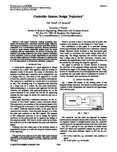
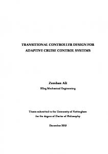
3 VALVE CONTROLLERS A valve controller (a positioner) has two main tasks: 1) to receive a valve opening setpoint from the automation system and 2) to control the valve position accordingly. In addition, various features are supported by different vendors and models. Optional features include on-line and self-diagnostics, a local user interface for commissioning and manual operation, remote operation support for various digital communications standards, automatic calibration and tuning. The best valve controllers can operate in harsh environmental conditions, they are tolerant against vibration and impacts, they are protected against humidity and dust, and resistant to dirty air, and built on wear resistant and sealed components (Metso 2016). Figure 2 illustrates the components of a valve controller. A valve setpoint is obtained from the mA signal, and the valve position is measured. A microcontroller compares setpoint and measurement, and calculates a control signal for the I/P converter, which controls the operating pressure (pilot pressure) of the pneumatic relay (output stage). When the pilot pressure changes, the pneumatic relay moves, and depending of movement direction it opens either of supply or exhaust channels. Air flows to or from the actuator and actuator pressure changes accordingly. The changing actuator pressure moves the control valve, and the cycle starts over by reading new values of valve setpoint and valve opening.
2
Figure 2. The main components of a valve controller (Metso 2016). The red frames refer to the components that were simulated during controller development: 1) I/P converter (prestage), 2) pneumatic relay (output stage), and 3) pneumatic actuator.
In addition to valve position measurement, the valve control algorithm may utilize a range of secondary measurements, like supply pressure, actuator pressure, I/P converter pressure, temperature, and relay position.
4 MODEL-BASED DESIGN, SIMULATIONS AND CONTROLLER DEVELOPMENT Recently, the popularity of model-based design has increased due to technology development and needs of improvements. The drivers of model-based design include: (Sandmann 2013 and Soini 2014) simulation tools development (simulation tools are getting easy to use, and building a complex model may be as easy as connecting ready-made component together, or CAD tools may include simulation possibilities), complexity (handling increased complexity is getting difficult with traditional design methods), and quality and cost (control algorithms can be developed earlier, simulations allow extensive testing of faults and extreme conditions). Companies that have used model-based design have report different advantages, like innovation (running what-if analysis in the virtual world allow quick-testing of new ideas), quality improvements, cost savings, and faster product development (Soini 2014). 3
We started with existing simulation models of valve packages (Pyötsiä 1991, Hietanen et al. 2011, Manninen 2012), and ended up with discrete models, which are extremely fast to simulate. With these models, we were able to develop and test the first functional controller in Matlab/Simulink. The valve package simulation included the following simulated components (red squares in Figure 2): 1.
I/P converter. The I/P converter produces a pneumatic pressure proportional to an input current from the microprocessor. The input current creates a magnetic field, which moves a flapper, which in turn affects air flow out of the I/P converter (Manninen 2012). We used static models of flapper position and air flows, and simulated air accumulation in the I/P converter. The output of this component is I/P converter pressure.
2.
Pneumatic relay. The I/P converter pressure moves the pneumatic relay, which opens either the supply to actuator or the actuator to exhaust air flow channel. The outputs of this component are the cross section areas of these channels. Moreover, simulation of pneumatic leakage was added to the model.
3.
Pneumatic Spring-Return Actuator. With the cross section areas of the pneumatic relay, air flows and air accumulation are simulated. Actuator movements are simulated based on pneumatic pressure forces, friction forces (static friction, coulomb friction, and viscous friction) and spring forces.
The first valve controller was developed against this simulator, with different valve package parameter combinations. These parameters included ·
Supply pressure variations. The NDX valve controller supports pressure ranges from 1.4 to 8 bar, which were simulated.
·
Actuator size and spring variations. The same valve controller is used for a wide range of actuators from 0.2 dm3 up to 100 dm3. Actuators are delivered with different spring stiffness selections.
·
Disturbances. We simulated different friction levels and amount of leakages.
The first valve controller was developed and tested with all these combinations. In addition to the control algorithm, an automatic tuning sequence was developed and run before each test. With this setup we were able to test valve control at system level, i.e. how valve position will follow valve setpoint. Naturally, control algorithm modifications were done to valve packages that revealed poor control quality.
5 DEVELOPMENT TOOLS During the development project of the Neles NDX valve controller, we have used software tools from Mathworks Inc. The first simulation tests were run in Matlab/Simulink. Next, we started using Simulink Realtime, which is a realtime operating system for testing embedded control in the laboratory. Simulink Realtime runs on an ordinary PC with I/O cards, and acts like an embedded controller. In addition, many useful features for debugging, monitoring, trend plotting, and parameter handling are supported. With Simulink Realtime, we tested our control algorithm against real actuators in laboratory. Later, when the first valve controller prototype was available, we started using Matlab Coder, Simulink Coder, and Embedded Coder for production code generation of the control algorithm. During the entire project, we used Matlab for analyzing generated data.
4
6 EXPERIENCES OF MODEL-BASED DESIGN The drawback of model-based design is that we need a simulation model of the controlled system. Resources are needed to develop the model, but it is important to understand that maintaining the model also requires resources. Usually, more resources are needed for model maintenance than developing the first model. In our case, model maintenance has meant adding various disturbances, adding non-ideal behaviour to the measurements (noise and nonlinearities), and extending the model from a single-acting to a double acting actuator. Modern, multi-domain simulators allow easy modeling by connecting ready-made components. However, we have seen that building the simulation model from mathematical relations, gives deep understanding of the controlled system, with respect to control design. We have seen that many coding errors can be detected at an early stage. Starting from writing code, we evaluate (i.e. test) every piece code with some example values obtained by simulation. This routine discloses most errors. Also, the possibility to instantly simulate each controller change with some predefined sequence, reveals many errors. An important advantage is that model-based design allows control design to be started much earlier than traditionally. In the past, control design and testing could not be started before the first prototype was available. With model-based design, we can start control design and testing when the first simulation model is available. At this stage, we may also detect other (non-control related) design errors in the system and suggest alternative solutions. Next we discuss some example advantages from the valve controller development. Example: Initial Specifications. At a very early state of the project, long before the first prototype was available, the valve position measurement designer wanted to know how much noise is allowed in the valve position measurement. Normally, it would be very difficult to answer such a question, and providing a wrong answer would imply hardware specification changes later in the project, which in turn could delay the entire project. However, simulating the control algorithm, with different noise levels, gave a good understanding of how the noise level imply control performance, and how it performs with respect to the overall control performance targets. Example, Fault-Tolerant Control. A valve controller must be resistant to various disturbances, such as sticky valves and pneumatic leakages (Manninen 2012). Early in the project, we defined these disturbances, and simulated different combinations of actuator types and faults. These simulations gave us a good understanding of the control algorithm robustness for various types of faults. Example, Control Development and Up Keeping. A typical, simple, control algorithm modification is done as follows. We run a simulation with the latest controller and add a breakpoint where the controller modification is made. Then, each additional new piece of code is tested by evaluating it in the Matlab environment, initiated with state, measurement, and parameter values from the simulation. This procedure eliminates syntax errors, and most bugs are detected at this stage. When the new code section is ready, we run some simulation cases selected according to the type of modification that was done. If results look OK, we proceed to code generation. Automatic code generation not only generates code, it also copies the new code to the version handling, which in turn compiles
5
a new firmware version, and starts robot testing of firmware. As a result, everything from code modification to system testing in laboratory, is done automatically.
6 SUMMARY AND CONCLUSIONS In our Neles NDX product development project, we have found many advantages with model-based design. Building a simulation model is an extra cost, but provides quick payback, as it gives a thorough understanding of the controlled system. We simulated different valve and actuator types, of different size, with various disturbances at an early stage. This gave us feedback of control quality at system level, which pays off as improved product quality. With early simulation exercises, we could start controller design before we had the first prototype. As a result, valve control worked successfully already for the first prototype.
6 REFERENCES Hietanen Ville, Friman Mats, Pyötsiä Jouni, Manninen Timo. Laatua järjestelmien simuloinnista. Automaatio XIX seminar. Finnish Society of Automation. Helsinki, Finland. 2011. Kirmanen Jari, Niemelä Ismo, Pyötsiä Jouni, Simula Markku, Hauhia Markus. Riihilahti Jari: The Flow Control Manual,.4th ed. Metso Automation. 1997 Manninen Timo. Fault Simulator and Detection for a Process Control Valve. PhD Thesis, Aalto University, Espoo, Finland 2012. Metso Flow Control: NELES® INTELLIGENT VALVE CONTROLLER, SERIES NDX. Technical Bulletin. 2016. Pyötsiä Jouni: A Mathematical model of a Control Valve. PhD Thesis. Helsinki University of Technology, Espoo, Finland. 1991. Sandmann Guido: Deploying Model-Based Design: How Industry Standards Influence Development Processes in the Automotive Industry and beyond Automotive Industry Manager. Mathworks Model-Based Design Workshop. Tampere, Finland. 2013. Soini Matias: Modeling and Simulation Practices in Control System Software Development. M.Sc. Thesis, Tampere University of Technology. Tampere, Finland, 2014.
6