the hand silhouette, which can then be used for shape-based matching [88, 119]. It .... ample, the American Sign Language recognition system by Starner et al.
Model-Based Hand Tracking Using A Hierarchical Bayesian Filter
Bj¨orn Dietmar Rafael Stenger St. John’s College March 2004
Dissertation submitted to the University of Cambridge for the degree of Doctor of Philosophy
Model-Based Hand Tracking Using A Hierarchical Bayesian Filter Bj¨orn Stenger
Abstract This thesis focuses on the automatic recovery of three-dimensional hand motion from one or more views. A 3D geometric hand model is constructed from truncated cones, cylinders and ellipsoids and is used to generate contours, which can be compared with edge contours and skin colour in images. The hand tracking problem is formulated as state estimation, where the model parameters define the internal state, which is to be estimated from image observations. In the first approach, an unscented Kalman filter is employed to update the model’s pose based on local intensity or skin colour edges. The algorithm is able to track smooth hand motion in front of backgrounds that are either uniform or contain no skin colour. However, manual initialization is required in the first frame, and no recovery strategy is available when track is lost. The second approach, tree-based filtering, combines ideas from detection and Bayesian filtering: Detection is used to solve the initialization problem, where a single image is given with no prior information of the hand pose. A hierarchical Bayesian filter is developed, which allows integration of temporal information. This is more efficient than applying detection at each frame, because dynamic information can be incorporated into the search, which helps to resolve ambiguities in difficult cases. This thesis develops a likelihood function, which is based on intensity edges, as well as pixel colour values. This function is obtained from a similarity measure, which is compared with a number of other cost functions. The posterior distribution is computed in a hierarchical fashion, the aim being to concentrate computation power on regions in state space with larger posterior values. The algorithm is tested on a number of image sequences, which include hand motion with self-occlusion in front of a cluttered background.
Acknowledgements
First and foremost, I wish to thank my supervisors Roberto Cipolla and Philip Torr who have both continuously shared their support and enthusiasm. Working with them has been a great pleasure. Over the past years I have also enjoyed working with a number of fellow PhD students, in particular Paulo Mendonc¸a and Arasanathan Thayananthan, with whom the sharing of authorship in several papers reflects the closeness of our cooperation. Present and former colleagues in the vision group have made the lab an excellent place to work, including Tom Drummond, Paul Smith, Adrian Broadhurst, Kenneth Wong, Anthony Dick, Duncan Robertson, Yongduek Seo, Bj¨orn Johansson, Martin Weber, Oliver Williams, Jason McEwen, George Vogiatzis, Jamie Shotton, Ramanan Navaratnam, and Ognjen Arandjelovi´c. The financial support of the Engineering and Physical Sciences Research Council, the Gottlieb-Daimler and Karl-Benz Foundation, the Cambridge European Trust and Toshiba Research have made my stay in Cambridge possible. I also thank St. John’s College and the Department of Engineering for supporting my participation in conferences and seminars and for providing a fine work environment. A very big ‘thank you’ goes to Sofya Poger for help with the data glove, to Nanthan, Ram, Ollie, Martin, Oggie, Phil, Bill Gibson and Simon Redhead for the time and effort put into proof-reading, and to Rei for the Omamori charm. Finally, heartfelt thanks go to my family for their immense support along the way. Bj¨orn Stenger
Contents
1 Introduction 1.1
1.2
2
Motivation . . . . . . . . . . . . . . . . . . . . . . . . . . . . . . . . . .
2
1.1.1
Limitations of existing systems . . . . . . . . . . . . . . . . . .
3
1.1.2
Approach . . . . . . . . . . . . . . . . . . . . . . . . . . . . . .
5
1.1.3
Limiting the scope . . . . . . . . . . . . . . . . . . . . . . . . .
5
Thesis overview . . . . . . . . . . . . . . . . . . . . . . . . . . . . . . .
6
1.2.1
Contributions of this thesis . . . . . . . . . . . . . . . . . . . . .
6
1.2.2
Thesis outline . . . . . . . . . . . . . . . . . . . . . . . . . . . .
7
2 Related Work 2.1
8
Hand tracking . . . . . . . . . . . . . . . . . . . . . . . . . . . . . . . .
8
2.1.1
2D hand tracking . . . . . . . . . . . . . . . . . . . . . . . . . .
9
2.1.2
Model-based hand tracking . . . . . . . . . . . . . . . . . . . . .
10
2.1.3
View-based gesture recognition . . . . . . . . . . . . . . . . . .
14
2.1.4
Single-view pose estimation . . . . . . . . . . . . . . . . . . . .
16
2.2
Full human body tracking . . . . . . . . . . . . . . . . . . . . . . . . . .
18
2.3
Object detection . . . . . . . . . . . . . . . . . . . . . . . . . . . . . . .
21
2.3.1
Matching shape templates . . . . . . . . . . . . . . . . . . . . .
22
2.3.2
Hierarchical classification . . . . . . . . . . . . . . . . . . . . .
24
Summary . . . . . . . . . . . . . . . . . . . . . . . . . . . . . . . . . .
26
2.4
3 A 3D Hand Model Built From Quadrics
27
3.1
Projective geometry of quadrics and conics . . . . . . . . . . . . . . . .
27
3.2
Constructing a hand model . . . . . . . . . . . . . . . . . . . . . . . . .
33
3.3
Drawing the contours . . . . . . . . . . . . . . . . . . . . . . . . . . . .
35
3.4
Handling self-occlusion . . . . . . . . . . . . . . . . . . . . . . . . . . .
38
3.5
Summary . . . . . . . . . . . . . . . . . . . . . . . . . . . . . . . . . .
39
iii
4 Model-Based Tracking Using an Unscented Kalman Filter
40
4.1
Tracking as probabilistic inference . . . . . . . . . . . . . . . . . . . . .
40
4.2
The unscented Kalman filter . . . . . . . . . . . . . . . . . . . . . . . .
43
4.3
Object tracking using the UKF algorithm . . . . . . . . . . . . . . . . .
45
4.4
Experimental results . . . . . . . . . . . . . . . . . . . . . . . . . . . .
48
4.5
Limitations of the UKF tracker . . . . . . . . . . . . . . . . . . . . . . .
51
4.6
Summary . . . . . . . . . . . . . . . . . . . . . . . . . . . . . . . . . .
52
5 Similarity Measures for Template-Based Shape Matching 5.1 5.2
5.3
5.4 5.5
55
Shape matching using distance transforms . . . . . . . . . . . . . . . . .
56
5.1.1
The Hausdorff distance . . . . . . . . . . . . . . . . . . . . . . .
60
Shape matching as linear classification . . . . . . . . . . . . . . . . . . .
61
5.2.1
Comparison of classifiers . . . . . . . . . . . . . . . . . . . . . .
62
5.2.2
Experimental results . . . . . . . . . . . . . . . . . . . . . . . .
64
5.2.3
Discussion . . . . . . . . . . . . . . . . . . . . . . . . . . . . .
67
Modelling skin colour . . . . . . . . . . . . . . . . . . . . . . . . . . . .
68
5.3.1
Comparison of classifiers . . . . . . . . . . . . . . . . . . . . . .
71
5.3.2
Experimental results . . . . . . . . . . . . . . . . . . . . . . . .
72
Combining edge and colour information . . . . . . . . . . . . . . . . . .
75
5.4.1
Experimental results . . . . . . . . . . . . . . . . . . . . . . . .
76
Summary . . . . . . . . . . . . . . . . . . . . . . . . . . . . . . . . . .
78
6 Hand Tracking Using A Hierarchical Filter
82
6.1
Tree-based detection . . . . . . . . . . . . . . . . . . . . . . . . . . . .
82
6.2
Tree-based filtering . . . . . . . . . . . . . . . . . . . . . . . . . . . . .
83
6.2.1
The relation to particle filtering . . . . . . . . . . . . . . . . . .
87
6.3
Edge and colour likelihoods . . . . . . . . . . . . . . . . . . . . . . . .
89
6.4
Modelling hand dynamics . . . . . . . . . . . . . . . . . . . . . . . . . .
90
6.5
Tracking rigid body motion . . . . . . . . . . . . . . . . . . . . . . . . .
91
6.5.1
Initialization . . . . . . . . . . . . . . . . . . . . . . . . . . . .
92
Dimensionality reduction for articulated motion . . . . . . . . . . . . . .
94
6.6.1
Constructing a tree for articulated motion . . . . . . . . . . . . .
96
Summary . . . . . . . . . . . . . . . . . . . . . . . . . . . . . . . . . .
99
6.6 6.7
7 Conclusion 7.1
103
Summary . . . . . . . . . . . . . . . . . . . . . . . . . . . . . . . . . . 103 iv
7.2 7.3
Limitations . . . . . . . . . . . . . . . . . . . . . . . . . . . . . . . . . 104 Future work . . . . . . . . . . . . . . . . . . . . . . . . . . . . . . . . . 104
v
List of Figures 1.1
Problem statement . . . . . . . . . . . . . . . . . . . . . . . . . . . . .
3
2.1
Components of a model-based tracking system . . . . . . . . . . . . . .
11
2.2
Components of a view-based recognition system . . . . . . . . . . . . . .
15
2.3
Components of a pose estimation system . . . . . . . . . . . . . . . . . .
17
2.4
Cascade of classifiers . . . . . . . . . . . . . . . . . . . . . . . . . . . .
25
3.1
Examples of quadratic surfaces . . . . . . . . . . . . . . . . . . . . . . .
28
3.2
A truncated ellipsoid . . . . . . . . . . . . . . . . . . . . . . . . . . . .
31
3.3
Projecting a quadric . . . . . . . . . . . . . . . . . . . . . . . . . . . . .
31
3.4
The geometric hand model . . . . . . . . . . . . . . . . . . . . . . . . .
33
3.5
Finger blueprints . . . . . . . . . . . . . . . . . . . . . . . . . . . . . .
34
3.6
Projecting cones and cylinders . . . . . . . . . . . . . . . . . . . . . . .
37
3.7
Projected contours of the hand model . . . . . . . . . . . . . . . . . . .
39
4.1
Flowchart of the UKF tracker . . . . . . . . . . . . . . . . . . . . . . . .
45
4.2
Tracking a pointing hand using local edge features . . . . . . . . . . . .
47
4.3
Tracking a pointing hand in two views . . . . . . . . . . . . . . . . . . .
48
4.4
Tracking a pointing hand with thumb motion in two views . . . . . . . .
49
4.5
Tracking an open hand using local edge features . . . . . . . . . . . . . .
50
4.6
Error comparison for different features . . . . . . . . . . . . . . . . . . .
51
4.7
Tracking a pointing hand using skin colour edges . . . . . . . . . . . . .
51
5.1
Computing the distance transform . . . . . . . . . . . . . . . . . . . . .
57
5.2
Chamfer cost function in translation space . . . . . . . . . . . . . . . . .
58
5.3
Chamfer matching using multiple orientations . . . . . . . . . . . . . . .
60
5.4
Templates and feature maps used for edge-based classification . . . . . .
63
5.5
Examples of training and test images . . . . . . . . . . . . . . . . . . . .
64
5.6
Including edge orientation improves classification performance . . . . . .
65
vi
0 List of Figures
1
5.7 5.8
ROC curves for edge-based classifiers . . . . . . . . . . . . . . . . . . . Colour likelihood in translation space . . . . . . . . . . . . . . . . . . .
66 70
5.9 5.10 5.11 5.12
Templates and feature maps used for colour-based classification Colour information helps to exclude background regions . . . . ROC curves for colour-based classifiers . . . . . . . . . . . . . Efficient evaluation of colour likelihoods . . . . . . . . . . . . .
. . . .
. . . .
. . . .
. . . .
. . . .
72 73 73 75
5.13 5.14 5.15 5.16
Determining the weighting factor in the cost function . Detection with integrated edge and colour features . . Detection results using edge and colour information . . Error comparison between UKF tracking and detection
. . . .
. . . .
. . . .
. . . .
. . . .
76 77 80 81
6.1 6.2 6.3
Hierarchical partitioning of the state space . . . . . . . . . . . . . . . . . Discretizing the filtering equations . . . . . . . . . . . . . . . . . . . . . Tree-based estimation of the posterior density . . . . . . . . . . . . . . .
85 86 88
6.4 6.5 6.6 6.7
Tracking a pointing hand . . . . . . . Error performance . . . . . . . . . . . Tracking out-of-image-plane rotation . Fast motion and recovery . . . . . . .
. . . .
. . . .
. . . .
. . . .
. . . .
. . . .
. . . .
. . . .
. . . .
. . . .
. . . .
. . . .
. . . .
. . . .
. . . .
. . . .
. . . .
. . . .
92 92 93 93
6.8 6.9 6.10 6.11
Automatic initialization . . . . . . . . . . Search results at different levels of the tree Variation along principal components . . Paths in the eigenspace . . . . . . . . . .
. . . .
. . . .
. . . .
. . . .
. . . .
. . . .
. . . .
. . . .
. . . .
. . . .
. . . .
. . . .
. . . .
. . . .
. . . .
. . . .
. . . .
94 95 97 97
. . . .
. . . .
. . . .
. . . .
. . . .
. . . .
6.12 Partitioning the state space . . . . . . . . . . . . . . . . . . . . . . . . . 98 6.13 Tracking articulated hand motion . . . . . . . . . . . . . . . . . . . . . . 100 6.14 Tracking a hand opening and closing with rigid body motion . . . . . . . 102
1 Introduction But finding a hand-detector certainly did not allow us to program one. David Marr (1945 – 1980)
1.1 Motivation The problem addressed in this thesis is the automatic recovery of the three-dimensional hand pose from a single-view video sequence. Additionally, extensions to multiple views are shown for a few cases. An example image from an input sequence is given in figure 1.1, along with a 3D hand model in the recovered pose. Tracking objects through image sequences is one of the fundamental problems in computer vision, and recovering articulated motion has been an area of research since the 1980s [59, 102]. The particular problem of hand tracking has been investigated for over a decade [29, 30, 109], and continues to attract research interest as the potential applications are appealing: A vision of computers or robots that are able to make sense of human hand motion has inspired researchers and film directors alike [15, 31, 88, 127, 128]. At the centre of interest is the development of human computer interfaces (HCI), where a computer can interpret hand motion and gestures and attach certain actions to them. Some examples are the manipulation of virtual objects, and the control of a virtual hand (an avatar) or a mechanical hand. If the pose of a pointing hand is recovered accurately, this can be interpreted by the computer as “selecting” a particular object, either on a screen or in the environment, and an action can be easily associated. A “digital desk” [146] may be a useful input device in museums or other public places, and touch-free input is also interesting for computer games, where it is already commercially available in a relatively simple form (e.g. the EyeToy system for the Sony Playstation 2). 2
1 Introduction
(a)
3
(b)
(c)
Figure 1.1: The problem addressed in this thesis. The three-dimensional pose of a hand is recovered from an input image. (a) The input image of a hand in front of cluttered background, (b) with the projected model contours superimposed, and (c) the corresponding 3D model in the recovered pose.
1.1.1
Limitations of existing systems
Given the complexity of the task, most approaches in the past have made a number of assumptions that greatly simplify the problem of detecting or tracking a hand. These include the following restrictions: • Uniform or static background: The use of a simple uniform background (e.g. black or blue) allows clean foreground segmentation of the hand [5, 113, 134]. If the camera is static, background subtraction can be used, assuming that the foreground appearance is sufficiently different from the background [90, 136]. In the case of edge-based trackers, the feature detection stage is made robust by the absence or elimination of background edges [109, 110]. However, using a uniform background is considered too restrictive for a general system, and the technique of background subtraction is unreliable when there are strong shadows in the scene, when background objects move or if the illumination changes [136]. • Clean skin colour segmentation: The goal of skin colour segmentation is to obtain the hand silhouette, which can then be used for shape-based matching [88, 119]. It has been shown that in many settings skin colour has a characteristic distribution, which can be distinguished from the colour distribution of background pixels [74]. However, one difficulty of this method is that not only hand regions are obtained, but also other skin coloured regions, such as the arm, the face, or background objects, for example wooden surfaces. The segmentation quality can be significantly improved when special hardware is available such as infrared lights [119].
4
1 Introduction • Delimitation of the wrist: Often it is assumed that the hand in the image can be easily segmented from the arm. If a person is wearing long non-skin coloured sleeves, the extraction of the hand silhouette is much simplified [113, 119, 134]. Lockton and Fitzgibbon [88] make this assumption explicit by requiring the user to wear a wristband. If such an “anchor feature” is supplied, the hand shape can be projected into a canonical frame, thus obtaining the orientation, translation and scale parameters. • Manual initialization: If a three-dimensional model is used for pose estimation, it is often assumed that the model is correctly aligned in the first frame [109, 110]. The problem can then be posed as an optimization problem, wherein the model parameters are adapted in each frame in order to minimize an error function. For user interfaces, however, it is desirable to make the initialization process automatic. • Slow hand motion: Given that the hand is moving slowly, a sequential optimization approach can be taken in which the parameters of a hand model are adapted in each frame. The solution from the previous frame is used to initialize the optimization process in the current frame [109, 110]. However, due to the number of local minima this approach does not work when hand motion is fast or when feature association is difficult due to self-occlusion. • Unoccluded fingertips: If the fingertips can be located in the image, the hand pose can be reconstructed by solving an inverse kinematics problem [149]. However, extracting the fingertip positions is not an easy task, and in many poses not all fingers are visible. Even though these assumptions hold in certain cases, they are considered too restric-
tive in the general case. For example, when a single input image is given, no knowledge of the background scene can be assumed. Similarly, it is not guaranteed that no other skin coloured objects are in the scene. Usually people are able to estimate the pose of a hand, even when viewed with one eye. This fact is proof of the existence of a solution to the problem. However, the underlying mechanisms of biological visual information processing, particularly at higher levels of abstraction, are currently not fully understood [81]. In 1972 Gross et al. [53] discovered neurons in the inferotemporal cortex of macaque monkeys that showed the strongest response when a hand shape was present in their visual field. However, the fact that such cells should exist does not tell us anything about how they do it. This is the context of David Marr’s quote at the beginning of this chapter.
1 Introduction
1.1.2
5
Approach
In this thesis a model-based approach is taken. By “model” we a mean geometric threedimensional hand model, which has the advantages of compact representation, correspondence with semantics, and the ability to work in continuous space. In the more general sense, our “model” encodes information about the shape, motion and colour that is expected in an image containing a hand. State variables are associated with the geometric model, which are estimated by a filter allowing integration of temporal information and image observations. In the case of hands, edge contours and skin colour features have been used as observations in the past [5, 90, 110, 119] and both of these features are used in this work. Two solutions are suggested for the estimation problem. The first solution is based on recursive Bayesian filtering using an extension of the Kalman filter, the unscented Kalman filter [78]. This approach makes use of a dynamic model to predict the hand motion in each frame and combines the prediction with an observation to obtain a pose estimate. It is shown that this approach works under certain assumptions, but it is too restrictive in the general setting. The second approach combines ideas from detection techniques and Bayesian filtering. A detection approach is used to solve the initialization problem, where a single image is given with no prior information of the hand pose. This is a hard task and raises a number of issues, such as how to find the location of a hand and how to discriminate between different poses. Perhaps the more important question is whether these two tasks should be separated at all. In this work, template matching is used to solve this problem: A large number of templates are generated by the 3D model and a similarity function based on edge and colour features scores the quality of a match. This is shown to work for a single frame, but using detection in every frame is not efficient. Furthermore, in certain hand poses, e.g. if a flat hand is viewed from the side, there is little image information that can be used for reliable detection. Thus, the idea is to use temporal information in order to increase the efficiency, as well as to resolve ambiguities in difficult cases. This leads to a hierarchical Bayesian filter. The proposed algorithm is shown to successfully recover the hand pose in challenging input sequences, which include hand motion with self-occlusion in front of a cluttered background, and as such represents the current state-of-the-art.
1.1.3
Limiting the scope
Two important applications are explicitly not considered within this thesis. The first is marker-based motion capture, widely used for animation purposes in the film or games
6
1 Introduction
industry, or for biomechanical analysis. Commercial motion capture systems use markers on the object in order to obtain exact point locations. They also work with multiple cameras to resolve ambiguities, which occur in a single view. The use of markers solves one of the most difficult tasks, which is the feature correspondence problem. The number of possible correspondences is reduced drastically, and once these are found, 3D pose recovery becomes relatively easy. In this thesis only the case of markerless tracking is considered. The second application, which we do not attempt to solve, is that of automatic sign language interpretation. Even though recovering 3D pose reliably could be used to interpret finger spelling, such a level of detail may not be required for these applications. For example, the American Sign Language recognition system by Starner et al. [128], relies on temporal information and only recovers the hand position and orientation. Also the finger spelling system of Lockton and Fitzgibbon [88], which can recognize 46 different hand poses, does not attempt to recover 3D information.
1.2 Thesis overview This section states the main contributions of this thesis, and gives a brief outline of the following chapters.
1.2.1
Contributions of this thesis
The main contributions of this thesis are: • a hierarchical filtering algorithm, which combines robust detection with temporal filtering; • the formulation of a likelihood function that fuses shape and colour information, significantly improving the robustness of the tracker. Minor contributions include: • the construction of a three-dimensional hand model using truncated quadrics as building blocks, and the efficient generation of its projected contours; • the application of the unscented Kalman filter to three-dimensional hand tracking in single and dual views.
1 Introduction
1.2.2
7
Thesis outline
Chapter 2.
This chapter presents a literature review of hand tracking, where the main
ideas of model-based tracking, view-based recognition and single view pose estimation are discussed. The similarities and differences to full human body tracking are made explicit. Finally, it gives a brief introduction to object detection methods, which are based on hierarchical approaches. Chapter 3. A method to construct a three-dimensional hand model from truncated cones, cylinders and ellipsoids is presented in this chapter. It starts with an introduction to the geometry of quadric surfaces and explains how such surfaces are projected into the image plane. The hand model, which approximates the anatomy of a real human hand, is then constructed using truncated quadrics as building blocks. It is also explained how self-occlusions can be handled when projecting the model contours. Chapter 4. This chapter first formulates the task of tracking as a Bayesian inference problem. The unscented Kalman filter is introduced within the context of Bayesian filtering and is applied to 3D hand tracking. Experiments using single and dual views demonstrate the performance of this method, but also reveal its limitations. Chapter 5. In this chapter similarity measures are examined, which can be used in order to find a hand in images with cluttered backgrounds. The suggested cost function integrates both shape and colour information. The chamfer distance function [9] is used to measure shape similarity between a hand template and an image. The colour cost term is based on a statistical colour model and corresponds to the likelihood of the colour data in an image region. Chapter 6. This chapter describes one of the main contributions of this work, which is the development of an algorithm, which combines robust detection with Bayesian filtering. This allows for automatic initialization and recovery of the tracker, as well as the incorporation of a dynamic model. It is shown how the dimensionality of articulated hand motion can be reduced by analyzing joint angle data captured with a data glove, and examples of 3D pose estimation from a single view are presented.
2 Related Work Study the past if you would define the future. Confucius (551 BC–479 BC)
This chapter gives an overview of the developments and the current state-of-the-art in hand tracking. Earlier reviews have been published by Pavlovi´c et al. [105] and Wu and Huang [150, 152]. The next section introduces the ideas behind model-based tracking, view-based recognition, and single-view pose estimation, highlighting the merits, as well as the limits of each approach for hand tracking. In section 2.2 the common ground as well as the differences to full human body tracking are pointed out. Finally, section 2.3 gives a brief introduction to general object detection methods, which have yielded good results for locating deformable objects in images.
2.1 Hand tracking For a long time the work on hand tracking could be divided into two streams of research, model-based and view-based approaches [105]. Model-based approaches use an articulated three-dimensional (3D) hand model for tracking. The model is projected into the image and an error function is computed, scoring the quality of the match. The model parameters are then adapted such that this cost is minimized. Usually it is assumed that the model configuration at the previous frame is known, and only a small parameter update is necessary. Therefore, model initialization has been a big obstacle. In most cases the model is aligned manually in the first frame. Section 2.1.2 reviews methods for modelbased hand tracking. In the view-based approach, the problem is formulated as a classification problem. A set of hand features is labelled with a particular hand pose, and a classifier is learnt 8
2 Related Work
9
Model-based 3D tracking
View-based pose estimation
Estimation of continuous 3D parameters
Discrete number of poses
Initialization required
Estimation from a single image
Single or multiple views
Single view
Tracking features reliably is difficult
Estimating nonlinear 3D–2D mapping is difficult
Table 2.1: Comparison of model-based and view-based approaches. from this training data. These techniques have been employed for gesture recognition tasks, where the number of learnt poses has been relatively limited. Section 2.1.3 gives an overview of methods for view-based gesture recognition. A summary of properties of the two approaches is listed in table 2.1. More recently, the boundaries between model-based and view-based methods have been blurred. In several papers [4, 5, 6, 113, 119] 3D models have been used to generate a discrete set of 2D appearances, which are matched to the image. These appearances are used to generate an arbitrary amount of training data, and a correspondence between 3D pose vector and 2D appearance is given automatically by the model projection. The inverse mapping can then simply be found by view-based recognition, i.e. the estimated pose is given by the 2D appearance with the best match. These methods have the potential to solve many of the problems inherent in model-based tracking. A number of tracking systems have been shown to work for 2D hand tracking. In the following section, some of these methods are reviewed.
2.1.1
2D hand tracking
Tracking the hand in 2D can be useful in a number of applications, for example simple user interfaces. In this context 2D tracking refers to methods, which use a single camera to track a hand, possibly with some scale changes, and do not recover 3D information about out-of-image-plane rotation or finger configuration. This is a much simpler problem than full 3D tracking for a number of reasons. First of all, the dimension of the search space is much smaller, i.e. there are only four degrees of freedom (DOF) for global motion, which are translation, scale and rotation in the image plane, whereas 3D tracking has six DOF for rigid body motion. Another factor is that hand poses can be easily recognized when
10
2
Related Work
the hand is fronto-parallel to the camera, because the visible area is relatively large and self-occlusion between different fingers is small. One example of a human computer interface (HCI) application is the vision-based drawing system presented by MacCormick and Isard [90]. The hand shape was modelled using a B-spline, and a particle filter was used to track the hand contour. The state space was partitioned for efficiency, decoupling the motions of index finger and thumb. Background estimation was used to constrain the search region, and seven DOF were tracked in real-time. The tracker was initialized by searching regions which were classified as skin colour [67]. A limitation of this method is the fact that the contour alone is not a reliable feature during fast hand movements. Laptev and Lindeberg [84] and Bretzner et al. [20] presented a system that could track an open hand and distinguish between five different hand states. Scale-space analysis was used to find intensity or colour blob features at different scales, corresponding to palm and fingers. Likelihood maps were generated for these features and were used to evaluate five hypothesized hand states that corresponded to certain fingers being bent or extended. Tracking was effected using a particle filter, and the system operated at 10 frames per second. It was used within a vision-based television remote control application. Von Hardenberg and B´erard [143] showed the use of an efficient but simple fingertip detector in some HCI applications. The system adaptively estimated the background and searched the foreground region for finger-like shapes at a single scale. This method only works for applications with a steady camera and relies on clean foreground segmentation, which is difficult to obtain in a general setting [136]. However, it requires no initialization and allows for fast hand motion. To summarize, a number of 2D tracking systems have been shown to work in HCI applications in real time. However, they are difficult to extend to 3D tracking without the use of a geometric hand model. The following section deals with 3D tracking, which has many more potential applications, but at the same time is a very challenging task.
2.1.2
Model-based hand tracking
A model-based tracking system generally consists of a number of components, as depicted in figure 2.1. The geometric hand model is usually created manually, but can also be obtained by reconstruction methods. Models that have been used for tracking are based on planar patches [153, 155], deformable polygon meshes [57] or generalized cylinders [36, 108, 109, 110, 118, 120, 121]. In some works the hand shape parameters are estimated together with the motion parameters, thus adapting the hand model to each user [118, 120,
2 Related Work
11
Input Image
3D Model
Feature Extraction
Model Projection
Error Function Computation
Optimization of Model Parameters / Filtering
Figure 2.1: Components of a model-based tracking system. A model-based tracking system employs a geometric 3D model, which is projected into the image. An error function between image features and model projection is minimized, and the model parameters are adapted. 121, 149]. The underlying kinematic structure is usually based on the biomechanics of the hand. Each finger can be modelled as a four DOF kinematic chain attached to the palm, and the thumb may be modelled similarly with either four or five DOF. Together with rigid body motion of the hand, there are 27 DOF to be estimated. Working in such a high dimensional space is particularly difficult because feature points that can be tracked reliably are sparse: the texture on hands is weak and self-occlusion occurs frequently. However, the anatomical design places certain constraints on the hand motion. These constraints have been exploited in different ways to reduce the search space. One type of constraint are the joint angle limits, defining the range of motion. Another very significant type is the correlation of joint movement. Angles of the same finger, as well as of different fingers, are not independent. These constraints can be enforced in different ways, either by parameter coupling or by working in a space of reduced dimension, e.g. one found by PCA [57, 153, 155]. Different dynamic models have been used to characterize hand motion. Standard techniques include extended Kalman filtering with a constant velocity model [120]. A more complex model is the eigendynamics model of Zhu et al. [155], where the motion of each finger is modelled as a 2D dynamic system in a lower dimensional eigenspace. For 2D motions Isard and Blake [68] have used model switching to characterize different
12
2
Related Work
types of motion. However, global hand motion can be fast in terms of image motion. Even though it is usually smooth, it may be abrupt and difficult to predict from frame to frame. Furthermore, Tomasi et al. [134] pointed out that finger flexion or extension can be as short as 0.1 seconds, corresponding to only three frames in an image sequence. These considerations increase the difficulty of modelling hand dynamics in a general setting. An approach suggested in [134] is to identify a number of key poses and interpolate the hand motion between them. Arguably the most important component is the observation model, in particular the selection of features that are used to update the model. Possible features are intensity edges [57, 109, 110], colour edges [90] or silhouettes derived from colour segmentation [87, 153]. Identification of certain key points has been attempted [118, 120, 121], e.g. looking for fingertips by searching for protrusions in the silhouette shape. In some cases, features have been used that require more computational effort, such as a stereo depth map [36] or optical flow [89]. Several systems combine multiple cues into a single cost function [87, 89, 153, 155]. One of the first systems for markerless hand tracking was that of Cipolla and Hollinghurst [29, 30], who used B-spline snakes to track a pointing hand from two uncalibrated views. In each view the affine transformation of the snake was estimated, and with a ground plane constraint the indicated target position was found. The system required a simple background, but it could operate in real-time. Three-dimensional articulated hand tracking was pioneered by Rehg and Kanade [109, 110] with their DigitEyes tracking system. The system used a 3D hand model, which was constructed from truncated cylinders and had an underlying kinematic model with 27 degrees of freedom. Tracking was performed by minimizing a cost function, which measured how well the model is aligned with the image. Two possible cost functions were suggested, the first is based on edge features [109], the second on template registration [110]. In the first method, the model cylinder axes were projected into the image and local edges were found. Similarly, fingertip positions were found. The error term was the sum of squared differences between projected points and image feature points, and it was minimized using the Gauss-Newton algorithm. The second method of template registration was used in order to deal with self-occlusion. An edge template was associated with each finger segment, together with a window function masking the contribution of occluded segments. Using two cameras and dedicated hardware, the system achieved a rate of ten frames per second when using local edge features. Off-line results were shown for the case of self-occlusion. A neutral background was required for reliable feature
2 Related Work
13
extraction. Heap and Hogg [57] used a 3D point distribution model [32], which was constructed from a 3D magnetic resonance image data set. The possible hand shapes were a linear combination of the five most significant eigenvectors added to the mean shape. This reduction in the number of parameters allowed for tracking from a single view. However, natural hand motion was not modelled accurately because the 3D shape changes are nonlinear. The model was first deformed, then rotated, scaled and translated, so that the contours matched the edges in the image. The system tracked 12 DOF in a limited range at 10 frames per second. Delamarre and Faugeras [36] pursued a stereo approach to hand tracking. A stereocorrelation algorithm was used to estimate a dense depth map. In each frame a 3D model was fitted to this depth map using the iterative closest points (ICP) algorithm. Using stereo information helped segment the hand from a cluttered background. However, the disparity maps obtained with the correlation algorithm were not very accurate as there are not many strong features on a hand. Shimada et al. [118, 120, 121] used a silhouette-based approach to tracking from single camera input. The positions of finger-like shapes were extracted from the silhouette and matched with the projection of a 3D model. A set of possible pose vectors was maintained and each one was updated using an extended Kalman filter. An optimal path was then found for the whole image sequence. The difficulty in this method is to identify finger-like shapes during unconstrained hand motion, particularly in cases of self-occlusion. Wu and Huang [149] used different techniques to reduce the dimensionality of the search space. Firstly, constraints on the finger motion were imposed, such as linear dependence of finger joint angles. Furthermore, the state space was partitioned into global pose parameters and finger motion parameters. These sets of parameters were estimated in a two-step iterative algorithm. The limitation of this method is that the fingertips have to be visible in each frame. In another approach, Wu, Lin and Huang [87, 153] learnt the correlations of joint angles from data using a data glove. It was found that hand articulation is highly constrained and that a few principal components capture most of the motion. For the training data the state space could be reduced from 20 to seven dimensions with loss of only five percent of the information, and finger motion was described by a union of line segments in this lower dimensional space. This structure was used for generating a proposal distribution in a particle filter framework.
14
2
Related Work
Zhou and Huang [155] analyzed hand motion in more detail, and introduced an eigendynamics model. As previously, the dimensionality of joint angle data was reduced using PCA. Eigendynamics are defined as the motion of a single finger, modelled by a 2D linear dynamic system in this lower dimensional eigenspace, reducing the number of parameters from 20 to 10. As in previous work [149], the global pose and finger motion parameters were estimated separately in an iterative scheme. By using a cost function based on intensity edges as well as colour, the robustness towards cluttered backgrounds was increased. Lu et al. [89] suggested that the integration of multiple cues can assist tracking of articulated motion. In their approach, intensity edges and optical flow were used to generate forces, which act on a kinematic hand model. One limitation of the method, however, is the assumption that illumination does not change over time. To summarize, 3D hand tracking has been shown to work in principle, but only for relatively slow hand motion and usually in constrained environments, such as plain backgrounds or controlled lighting. The problem is ill-posed in a single view, because in some configurations the motion is very difficult to observe [15, 100]. In order to deal with these ambiguities, most systems use multiple cameras. A further issue is the initialization of the 3D model. When starting to track or when track is lost, an initialization or recovery mechanism is required, as presented by Williams et al. for region-based tracking [147]. This problem has been solved either by manual initialization or by finding the hand in a fixed pose. Generally, this task can be formulated as a hand detection problem, which has been addressed by view-based methods. The next section gives a short review of this approach.
2.1.3
View-based gesture recognition
View-based methods have traditionally been used for gesture recognition. This is often posed as a pattern recognition problem, which may be partitioned into components such as shown in figure 2.2. These methods are often described as “bottom-up” methods, because low-level features are used to infer higher level information. The main problems, which need to be solved in these systems are how to segment a hand from a general background scene and which features to extract from the segmented region. The classification itself is mostly done using a nearest neighbour classifier or other standard classification methods [42]. Generally, the classifier is learnt from a set of training examples and assigns the input image to one of the possible categories. In the following paragraphs only a few selected papers in gesture recognition are described. More thorough reviews can be found in [105, 152].
2 Related Work
15 Input Image
Segmentation
Feature Extraction
Classification
Figure 2.2: Components of a view-based recognition system. View-based recognition is often treated as a pattern recognition problem and a typical system consists of components as shown above. At the segmentation stage the hand is separated from the background. Features are then extracted, and based on these measurements the input is classified as one of many possible hand poses. The classifier is designed using a set of training patterns. Cui and Weng [34, 35] presented a system for hand sign recognition, which integrated segmentation and recognition. In an off-line process, a mapping was learnt from local hand subwindows to a segmentation mask. During recognition, regions of image motion were identified, and local subwindows of different sizes were used to hypothesize a number of segmentations. Each hypothesis was then verified by using a classifier on the segmented region. Features were selected by discriminant analysis and a decision tree was used for classification. The system recognized 28 different signs with a recognition rate of 93%. The segmentation step was the computational bottleneck and took approximately one minute per frame on an Indigo workstation, whereas the classification required only about 0.1 seconds. Another limitation of this approach is the assumption that the hand is the only moving object in the scene. Triesch and Von der Malsburg [137] built a hand gesture interface for robot control. Elastic 2D graph matching was employed to compare twelve different hand gestures to an image. Gabor filter responses and colour cues were combined to make the system work in front of cluttered backgrounds. This system achieved a recognition rate of 93% in simple backgrounds and 86% in cluttered backgrounds. Wu and Huang [151] introduced a method based on the EM algorithm to combine labelled and unlabelled training data. Using this approach, they classified 14 different hand postures in different views. Two types of feature vectors were compared: a combination of texture and shape descriptors, and a feature vector obtained by principal component analysis (PCA) of the hand images. The features obtained by PCA yielded better perfor-
16
2
Related Work
mance, and a correct classification rate of 92% was reported. Lockton and Fitzgibbon [88] built a real-time gesture recognition system for 46 different hand poses, including letter spellings of American Sign Language. Their method is based on skin colour segmentation and uses a boosting algorithm [46] for fast classification. The user was required to wear a wristband so that the hand shape can be easily mapped to a canonical frame. They reported a recognition rate of 99.87%; this is the best recognition result achieved so far, however, a limitation of the system is that controlled lighting conditions are needed. Tomasi et al. [134] used a classification approach together with parameter interpolation to track hand motion. Image intensity data was used to train a hierarchical nearest neighbour classifier (24 poses in 15 views), classifying each frame as one of 360 views. A 3D hand model was then used for visualizing the motion. The parameters for the 24 poses were roughly fixed by hand and the model parameters were interpolated for transitions between two poses. The system could handle fast hand motion, but it relied on clean skin colour segmentation and controlled lighting conditions, in a manner similar to that of Lockton and Fitzgibbon. It may also be noted that many other papers in gesture recognition, such as the sign language recognition system by Starner et al. [128], make heavy use of temporal information. American Sign Language has a vocabulary of approximately 6,000 temporal gestures, each representing one word. This is different from finger spelling, which is used for dictating unknown words or proper nouns. The hand tracking stage in [128] does not attempt to recover detail; it recovers only a coarse description of the hand shape, as well as its position and orientation. Methods from automated speech recognition, such as hidden Markov models, can be used for these tasks. Starner et al. reported a recognition rate of 98% using a vocabulary of 40 words. To summarize, view-based methods have been shown to be effective at discriminating between a certain number of hand poses, which is satisfactory for a number of applications in gesture recognition. One of the main problems in view-based methods is the segmentation stage. This is often done by skin colour segmentation, which requires the user to wear long sleeves or a wristband. Another option is to test several possible segmentations, which increase the recognition time.
2.1.4
Single-view pose estimation
More recently, a number of methods have been suggested for hand pose estimation from a single view. A 3D hand model is used to generate 2D appearances, which are matched
2 Related Work
17
Input Image
3D Model
Segmentation
Model Projection
Feature Extraction
Database of Views
Error Function Computation
Classification / Ranking
Figure 2.3: Components of a pose estimation system. This figure shows the components of a system for pose estimation from a single frame. A 3D geometric model is used to generate a large number of 2D appearances, which are stored in a database. At each frame, the input image is compared to all or a number of these views. Either a single pose or a ranking of possible poses is returned based on a matching error function. to the image, and the mapping between 3D pose and 2D appearance is given directly by projecting the model into the image, see figure 2.3. Shimada, Kimura and Shirai [119] presented a silhouette-based system for hand pose estimation from a single view. A shape descriptor was extracted and matched to a number of pre-computed models, which were generated from a 3D hand model. A total of 125 poses, each in 128 views was stored, giving a total of 16,000 shapes. In order to avoid exhaustive search at each frame, a transition network between model shapes was constructed. At each time step a set of hypotheses was kept, and only the neighbourhood of each hypothesis was searched. Real-time performance was achieved on a 6 personal computer (PC) cluster. Infra-red illumination and a corresponding lense filter were used to improve colour segmentation. Rosales et al. [113] also estimated the 3D hand pose from the silhouette in a single view. The silhouette was obtained by colour segmentation, and shape moments were used as features. The silhouette was matched to a large number of models, generated by projecting a 3D model in 2,400 different configurations from 86 viewpoints (giving a total of 206,400 shapes). The mapping from feature space to state space was learnt from
18
2
Related Work
example silhouettes generated by a 3D model. A limitation of the two previous methods is that the silhouette shape is not a very rich feature, and many different hand poses can give rise to the same silhouette shape in cases of self-occlusion. Athitsos and Sclaroff [4, 5] followed a database retrieval approach. A database of 107,328 images was constructed using a 3D model (26 poses in 4128 views). Different similarity measures were evaluated, including chamfer distance, edge orientation histograms, shape moments and detected finger positions. A weighted sum of these was used as a global matching cost. Retrieval times of 3-4 seconds per frame on a 1.2 GHz PC were reported in the case of a neutral background. In [6] the approach was extended to cluttered backgrounds by including a line matching cost term in the similarity measure. Processing time increased to 15 seconds per frame. Retrieval efficiency was addressed in [3], where the symmetric chamfer distance was used as a similarity measure. Fast approximations to the nearest neighbour classifier were explored to reduce the search time. This was done by learning an embedding from the input data into Euclidean space, where distances can be rapidly computed, while trying to preserve the relative proximity structure of the data. Pose estimation techniques from a single view are attractive, because they potentially solve the initialization problem in model-based trackers. In fact, if they were efficient enough, they could be used for pose estimation in each input frame independently. The observation model is a key component when adopting a database-retrieval method. Ideally, the similarity function should have a global minimum at the correct pose, and it should also be smooth around this minimum to tolerate some discretization error. As in view-based recognition, segmentation is a difficult problem. The methods presented above require either a clean background [4, 5, 113, 119] or a rough segmentation [6] of the hand. The following section gives a brief review of the related field of full human body tracking.
2.2 Full human body tracking Both hand tracking and full human body tracking can be viewed as special cases of tracking non-rigid articulated objects. Many of the techniques for human body tracking described in the literature can be applied to hand tracking as well. Therefore this section gives a brief review of methods used for tracking people, which is still a very active research area. For more extensive reviews the reader is referred to the papers by Aggarwal and Cai [1] and Moeslund and Granum [98]. Despite the obvious similarities between the two domains, there are a number of key
2 Related Work
19
differences. First of all, the observation model is usually different for hand and body tracking. Due to clothing, full body trackers have to handle a larger variability, but texture or colour of clothing provide more reliable features, which can be used for tracking [107]. Another option is to find people in images by using a face detector. In hand tracking, it is difficult to find features that can be tracked reliably due to weak texture and selfocclusion. On the other hand, skin colour is a discriminative feature, which is often used to segment the hand from the background. Another difference is the system dynamics in both cases. In human body motion, the relative image motion of the limbs is usually much slower than for hands. Global hand motion can be very fast and also finger motion may only take a fraction of a second [134]. These factors make the dynamics of the hand much harder to model than regular motion patterns such as walking or running. However, hand tracking is usually done in the context of HCI, and feedback from higher levels can be used to interpret the motion, for example in sign language recognition systems. As pointed out by Moeslund and Granum [98], most body motion capture systems make various assumptions related to motion and appearance. Typical assumptions are that the subject remains inside the camera view, that the range of motion is constrained, that lighting conditions are constant, or that the subject is wearing tight-fitting clothes. Most of these conditions can be made to hold in controlled environments, e.g. for motion capture applications. For robustness in less restrictive environments, such as HCI or surveillance applications, an initialization and recovery mechanism needs to be available. Trackers based on 3D models have a relatively long tradition in human body tracking. The first model-based trackers were presented by O’Rourke and Badler [102] and Hogg [59]. The system of Hogg already contained all the elements of figure 2.1, namely a 3D geometrical model with body kinematics, an observation model, and a method to search for the 3D parameters, which optimally align the model with the image. These issues need to be addressed in every model-based tracker. The first geometrical model, suggested by Marr and Nishihara [92], is a hierarchical structure wherein each part is represented by a cylinder. This model is used in Hogg’s tracking system [59]. Other primitives have been used such as boxes or quadrics, which include cylinders, cones and ellipsoids [19, 48, 95], deformable models [79] or implicit surfaces [106]. The underlying kinematical model is arranged in a hierarchical fashion, the torso being the root frame of reference, relative to which the coordinate systems of the body limbs are defined. A number of different observation models have been suggested to match the model
20
2
Related Work
projection to the image. Examples of observations used are: edge contours [41, 48, 59, 125], foreground silhouettes [37, 106], optical flow [19, 125], dense stereo depth maps [54, 106], or multi-view voxel data [95]. Several works combine a number of these features into one cost term. In some cases, a model with weak or no dynamics is used, and the model parameters are optimized at each frame, such that they minimize a cost function based on observations [37, 59, 106, 125]. When a dynamic model is used, the motion in consecutive frames can be predicted and integrated with the observation within a filtering framework. Possible choices are extended Kalman filtering [79, 95], or versions of particle filtering [38]. The human body dynamics have been modelled with constant velocity or constant acceleration models [48, 79], switched linear dynamic models [104] or example-based models [122]. The majority of model-based 3D body trackers require multiple views in order to reduce ambiguity. The high dimensionality of the state space, together with self-occlusions and depth ambiguity make tracking in a single view an ill-posed problem [100]. The cost function in the monocular estimation problem is highly multi-modal and there exist many possible inverse kinematic solutions for one observation. Choosing the wrong minimum leads to loss of track, therefore reliable tracking requires the maintenance of multiple hypotheses. Sminchisescu and Triggs [125] address this problem by using a cost function, which includes multiple cues, such as edge intensity and optical flow, and adopting a sophisticated sampling and search strategy in the 30 dimensional state space. Another, complementary strategy to resolve this ambiguity is to learn dynamic priors from training data of motions [18, 60, 122]. For simple HCI applications blob trackers may be adequate, for example the Pfinder system [148]. Typically a person is modelled by a number of ellipsoids, which are matched from frame to frame using an appearance descriptor, such as a colour histogram. Isard and MacCormick [69] combined blob tracking with particle filtering in their BraMBLe system. The body shape was modelled as a single generalized cylinder, and the system could track the position of multiple people in a surveillance application, where a static camera was assumed. There have been only few papers on 3D body pose estimation from a single image. One example is the method of Mori and Malik [99] who used a shape context descriptor [11] to match the input image to a number of exemplar 2D views. The exemplars were labelled with key points, and after registering the input shape, these points were used to reconstruct a likely 3D pose. This estimation algorithm was applied to each frame in a
2 Related Work
21
video sequence independently. Another method was presented by Shakhnarovich et al. [117] who generated a large number of example images using 3D animation software. The technique of parameter sensitive hashing was introduced to learn a hash function in order to efficiently retrieve approximate nearest neighbours with respect to both feature and parameter values. This approach is very similar to the method of Athitsos and Sclaroff [4] for hand pose estimation, where the problem was solved by a fast nearest neighbour search in the appearance domain. In a parts-based approach to people detection, such as the one by Felzenszwalb and Huttenlocher [44], “bottom-up” and “top-down” methods are combined. The body is represented by a collection of body parts, e.g. torso, head and limbs, and each of these is matched individually. The body pose is found by optimizing a cost function which takes the global configuration into account. These methods are promising as they reduce the search complexity significantly and they have recently been extended to threedimensional body tracking from multiple views [123].
2.3 Object detection One of the main challenges in tracking is initialization and recovery. This is necessary in HCI applications, where the user can move in and out of the camera view, and manual re-initialization is not a desirable option. Hand or full body tracking systems that rely on incremental estimation and do not have a recovery mechanism have been demonstrated to track accurately, but not over very long image sequences. Using a filter that supports multiple hypotheses is necessary to overcome ambiguous frames so that the tracker is able to recover. Another way to overcome the problem of losing lock is to treat tracking as object detection at each frame. Thus if the target is lost at one frame, subsequent frames are not affected. For example, current face detection systems work reliably and fast [141] without relying on dynamic models. However, detectors tend to give multiple positive responses in the neighbourhood of a correct match, and temporal information is useful to render such cases unambiguous. The following subsections review template matching techniques, which have been introduced in the context of object detection. Some of these methods have become so efficient that they can be implemented in real time systems, e.g. automated pedestrian detection in vehicles [47].
22
2.3.1
2
Related Work
Matching shape templates
Template-based methods have yielded good results for locating deformable objects in a scene with no prior knowledge, e.g. for hands or pedestrians [6, 47]. These methods are made robust and efficient by the use of distance transforms such as the chamfer or Hausdorff distance between template and image [9, 16, 62, 64], and were originally developed for matching a single template. Chamfer matching for a single shape was introduced by Barrow et al. [9]. It is a technique for finding the best match of two sets of edge points by minimizing a generalized distance between them. A common application is template-to-image matching, where the aim is to locate a previously defined object in the image. In most practical applications, the shape template is allowed to undergo a certain transformation, which needs to be dealt with efficiently. No explicit point correspondences are determined in chamfer matching, which means that the whole parameter space needs to be searched for an optimum match. In order to do this efficiently, the smoothness property of the chamfer distance can be exploited. If the change in the transformation parameters is small, the chamfer distance change is also small. This motivated the multi-resolution approaches of Borgefors for chamfer matching [16] and Huttenlocher and Rucklidge for Hausdorff matching [65]. Borgefors introduced the hierarchical chamfer matching algorithm [16], where a multi-resolution pyramid of edge images is built and matching proceeds in a coarse-to-fine manner. At the coarsest level, the transformation parameters are optimized, starting from points, which are located on a regular grid in parameter space. From these optima the matches at the next level of resolution are computed, and locations where the cost increases beyond a threshold are rejected and not further explored. Shape matching is demonstrated for Euclidean and affine transformations. However, a careful adjustment of step lengths for optimization and rejection thresholds is required and the algorithm only guarantees a locally optimal match. Huttenlocher and Rucklidge [65] used a similar approach to search the 4D transformation space of translation and independent scaling of the – and � –axis. The parameter space is tesselated at multiple resolutions and the centre of each region is evaluated. Bounds on the maximum change in cost are derived for the transformation parameters and regions in parameter space are eliminated in a coarse-to-fine search. Within this particular 4D transformation space the method is guaranteed not to miss any match, however, it is not straightforward to extend to other transformations, such as rotations. Both methods were developed for matching a single shape template. Three-dimensional objects can be recognized by representing each object by a set of 2D views. This multi-
2 Related Work
23
view based representation has been used frequently in object recognition [83]. These views, together with a similarity transformation can then be used to approximate the full 6D transformation space. In the case when these shapes are obtained from training examples, they are often referred to as exemplars. Breuel [21, 22] proposed an alternative shape matching algorithm by subdividing the transformation space. The quality of a match assigned to a transformation is the number of template points that are brought within an error bound of some image point. For each sub-region of parameter space an upper bound on this quality of match is computed, and the global optimum is found by recursive subdivision of these regions. A key suggestion was that multiple templates could be dealt with efficiently by using a tree structure [47, 101]. Olson and Huttenlocher [101] used agglomerative clustering of shape templates. In each iteration the two closest models in terms of chamfer distance are grouped together. Each node only contains those points, which the templates in the subtree have in common. During evaluation the tree is searched from the root and at each node model points, which are too far away from an image edge are counted. This count is propagated to the children nodes and the search is stopped once a threshold value is reached. The threshold value corresponds to an upper bound on the partial Hausdorff distance between templates. This allows for early rejection of models, however, the gain in speed is only significant if the models have a large number of points in common. For this to be likely, a large number of model views is necessary and it is not clear which and how many views to use. Gavrila [47, 49] suggested forming the template hierarchy by optimizing a clustering cost function. His idea is to group similar templates and represent them with a single prototype template together with an estimate of the variance of the error within the cluster, which is used to define a matching threshold. The prototype is first compared to the image and only if the error is below the threshold are the templates within the cluster compared to the image. This clustering is done at various levels, resulting in a hierarchy, in which the templates at the leaf level cover the space of all possible templates. The method is used in the context of pedestrian detection from a moving vehicle. A three-level tree is built from approximately 4,500 templates, which includes a search over five scales for each template. Detection rates of 60–90% are reported by using the chamfer distance alone. An extension of the system includes a further verification step based on a nonlinear classifier [47]. An approach to embed exemplar-based matching in a probabilistic tracking framework was proposed by Toyama and Blake [135]. In this method, templates are clustered
24
2
Related Work
using a � -medioid clustering algorithm. A likelihood function is estimated as a Gaussian mixture model, where each cluster prototype defines the centre of a mode. The dynamics are encoded as transition probabilities between prototype templates, and a first order dynamic model is used for the continuous transformation parameters. The observation and dynamic models are integrated in a Bayesian framework and the posterior distribution is estimated with a particle filter. A problem with template sets is that their size can grow exponentially with object complexity.
2.3.2
Hierarchical classification
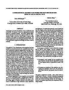
This section presents another line of work in the area of object detection, which has been shown to be succesful for face detection. The general idea is to slide windows of different sizes over the image and classify each window as face or non-face. Alternatively, by scaling the image, a window of the same size, typically of size ������� � pixels, can be used. The task thus is formulated as a pattern recognition problem, and the methods differ by which features and which type of classifier they use. Most of the papers deal with the case of single view detection. Multiple views can be handled by separately training detectors for images taken from other views. Variation in lighting and contrast is either handled by a normalization step during pre-processing, or by explicitly including a large number of training examples in different lighting conditions. Rowley, Baluja and Kanade [114] used a neural network-based classifier. After preprocessing, the sub-window were fed into a multi-layer neural network, which returns a real value between � , corresponding to a face, and �� , corresponding to no face. The outputs of different filters were then combined in order to eliminate overlapping detections. Schneiderman and Kanade [115] learnt the appearance of faces and of non-face patches in frontal and side-view by representing them as histograms of wavelet coefficients. The detection decision for each window was based on the maximum likelihood ratio. Romdhani et al. [112] introduced a cascade of classifiers where regions which are unlikely to be faces were discarded early, and more computational resources was spent in the remaining regions (see figure 2.4). This was done by sequential evaluation of support vectors in an SVM classifier. Viola and Jones [141] introduced rectangle features, which are differences of sums of intensities over rectangular regions in the image patch. These can be computed very efficiently by using integral images [33, 141]. A cascade of classifiers was constructed,
2 Related Work
25 Subwindow I
C1( I )
0
Reject
1
C2( I )
0
Reject
1
C3( I )
0
Reject
1 Further Processing
Figure 2.4: Cascade of classifiers. A cascade of classifiers ��� , ��� , and ��� , with increasing complexity. Each classifier has a high detection rate and a moderate false positive rate. Subwindows � which are unlikely to contain an object are rejected early, and more computational effort is spent on regions which are more ambiguous. arranged in successively more discriminative, but also computationally more expensive, order. Feature selection and training was done using a version of the AdaBoost algorithm [46]. Li et al. [86] extended the approach of Viola and Jones to multi-view detection. The range of head rotation was partitioned successively into smaller sub-ranges, discriminating between seven distinct head rotations. An improved boosting technique was used in order to reduce the number of necessary features. It is difficult to compare the performance of the methods presented, as in some cases different testing data was used, in other cases only the detection rate at a fixed false detection rate was reported. The detection rates of all systems are fairly comparable, however, the best performance has been reported for the Schneiderman-Kanade detector. The Viola-Jones detector is the fastest system for single-view detection, running in real-time. The question arises whether these methods could be applied for detecting or tracking a hand. An important difference between hands and faces is that hand images can have a much larger variation in appearance due to the large number of different poses. It would be surprising to find that only a few simple features could be used to discriminate hands from other image regions. Thus it is necessary to search over different poses as well as over views. This also means that a very large training set is necessary; Viola and
26
2
Related Work
Jones used nearly 5,000 face images for single-view detection [141]. There is also a large variation in hand shape, and in most poses, a search window containing the hand will include a larger number of background pixels. It may be necessary to use more discriminative features than rectangle filters based on intensity differences. For example, Viola et al. [142] included simple motion features to apply their framework to pedestrian detection. If shape is to be used as a feature, then this framework becomes very similar to the hierarchical shape matching methods described in section 2.3.1.
2.4 Summary This chapter has introduced a number of different approaches to detecting, tracking and interpreting hand motion from images. Accurate 3D tracking of hand or full body requires a geometric model, as well as a scheme to update the model given the image data. A range of hand tracking algorithms have been surveyed, using single or multiple views. The problem is ill-posed when using a single camera, and a number of methods have been suggested to reduce the number of parameters that need to be estimated. A shortcoming of these methods is the lack of an initialization and recovery mechanism. View-based methods could be used to solve this problem. However, view-based gesture recognition systems generally assume that the segmentation problem has already been solved, and most of them discriminate between a few gestures only. Single-view pose estimation attempts to recover the full 3D hand pose from a single image. This is done by matching the image to a large database of model-generated hand shapes. However, the mapping from a single 2D view to 3D pose is inherently ambiguous, and methods that are based on detection alone ignore temporal information, which could resolve ambiguous situations. In order to be able to accurately recover 3D information about the hand pose a 3D geometric hand model is essential, and the following chapter presents a method to construct such a model using truncated quadrics as building blocks.
3 A 3D Hand Model Built From Quadrics Treat nature by means of the cylinder, the sphere, the cone, everything brought into proper perspective. Paul C´ezanne (1839–1906)
In this work a model-based approach is pursued to recover the three-dimensional hand pose. The model is used to encode prior knowledge about the hand geometry and valid hand motion. It also allows the pose recovery problem to be formulated as a parameter estimation task and is therefore central to this work. In chapter 4 the model is used to generate contours for tracking with an unscented Kalman filter, and in chapters 5 and 6 it is used to generate templates, which are used for shape-based matching. This chapter explains how to construct a three-dimensional hand model using truncated quadrics as building blocks, approximating the anatomy of a real human hand. This approach uses results from projective geometry in order to generate the model projection as a set of conics, while handling cases of self-occlusion. As a theoretical background, a brief introduction to the projective geometry of quadrics is given in the next section. For textbooks on this topic, the reader is referred to [28, 56, 116].
3.1 Projective geometry of quadrics and conics A quadric � is a second degree implicit surface in 3D space. It can be represented in homogeneous coordinates as a symmetric ����� matrix � . The surface is defined by the points � , which satisfy the equation �������
�
27
�!
(3.1)
28
3 A 3D Hand Model Built From Quadrics
w
d
w
d
y0
π0
h
h w
d
x
z
x
z
x
z
x
z
y1
π1
y
y
y
y
(a)
(b)
(c)
(d)
Figure 3.1: Examples of quadratic surfaces. This figure shows different surfaces corresponding to the equations in the text: (a) ellipsoid, (b) cone, (c) elliptic cylinder, (d) pair of planes. where �"�$# &% � %(')% �+* � is a homogeneous vector representing a 3D point. A quadric has 9 degrees of freedom. Equation (3.1) is simply the quadratic equation: , �.-/�
�
� �
, �0- �1� , �0- � ' 2
� , �.- �
�� 2� , �.- � 3' 2� , �0- �3� ' 4� , �.- 5
4� , �0- 51�� 2� , �0- 5 ' , 56- 57�8�
(3.2) Different families of quadrics are obtained from matrices � of different ranks. Figure 3.1 shows examples of their geometric interpretation. These particular cases of interest are: • Ellipsoids, represented by matrices � with full rank. The normal implicit form of an ellipsoid centred at the origin and aligned with the coordinate axes is given by � 9 �
: �
�
; �
and the corresponding matrix is given by ?@ � @ BDC � E�C � �>� A � � � �
' �
< � �=� %
� �
F� �
C
�
(3.3)
GIH �
� J
� �
H
(3.4)
Other examples of surfaces which can be represented by matrices with full rank are paraboloids and hyperboloids. If the matrix � is singular, the quadric is said to be degenerate.
3 A 3D Hand Model Built From Quadrics
29
• Cones and cylinders, represented by matrices �
with K0L�MONQP.�2R��TS .
The equation of a cone aligned with the � -axis is given by � � ; �
� 9 � :
' �
< � �U� %
(3.5)
and the corresponding matrix is given by ?@ �>�
@ BO� C � A � �
�
E� �
�
� F �C � C
�
GIH H
� �
(3.6)
� J �
An elliptic cylinder, aligned with the � -axis, is described by �
' �
< � �=� %
9 �
(3.7)
and the corresponding matrix is given by ?@ �>�
@ BD� C � A � �
�
�
� �
�
� F �C �
GIH H
� �
(3.8)
� J
� V
• Pairs of planes WYX and WZ� , represented as �>�8WYX(W � � [W��\W �X with K6L�MONQP]�4R^�U� . For example, a pair of planes, which are parallel to the 3' -plane can be described by the equation: (3.9) P_� `� XaRbPc�d e�f�gRh�U� % in which case WjiZ��#k� % � % � % Y��Xl* � and WYm7�n#k� % � % � % :�f�]* � . The corresponding matrix is given by ?@
@ � �n�
A �
�
�
� �
�
�
xoyq\s\tu� q6vcw
�
�
GIH �
�
porq\s\tu� q6vcw J � � X1�z�
H
(3.10)
Coordinate transformations Under a Euclidean transformation { the shape of a quadric is preserved, but the matrix representation changes. Given a point � on quadric � , the equation of quadric � | , on which the transformed point |� � {�� lies can be
30
3 A 3D Hand Model Built From Quadrics
derived as follows: �U�
(3.11)
� � P{ � {! � R3�UP{} { Ru� �U� � Pc{V�pR � Pc{! � �2{} RP{���Rh�U�
(3.12)
|� � � | |�
(3.14)
� � �}� ~ ~ ~
�
(3.13)
�U�}
� | �{ ���4{ . The matrix { represents a Thus the matrix � is mapped to a matrix � � Euclidean transformation, and { and { can be written in homogeneous coordinates as {=�
p �
and
�x
{
�
�
�
�
�
�
(3.15)
Equivalently, this implies that any quadric matrix � | , representing an ellipsoid, cone or cylinder can be factored into components representing its shape, given in normal implicit form as in section 3.1, and motion in form of a Euclidean transformation. Truncated quadrics By truncating quadrics, they can be used as building blocks for modelling more complex shapes [109, 130]. For any quadric � the truncated quadric �x can be obtained by finding points � satisfying:
and
�����}��U�
(3.16)
� �1 �� %
(3.17)
where is a matrix representing a pair of clipping planes, see figure 3.2. It can be ensured that �x� � � for points between the clipping planes, by evaluating this equation for a point at infinity in the direction of one of the plane normal vectors, and if it is positive, the sign of is changed. Projecting a quadric In order to determine the projected outline of a quadric for a normalized projective camera ��#ld * , the quadric matrix � is written as � (3.18) � The camera centre and a point in image coordinates define a ray �PczRh��# % * � in 3D space. The inverse depth of a point on the ray is determined by the free parameter , such �>�
that the point �[Pc�R is at infinity and �PR is at the camera centre (see figure 3.3). The point of intersection of the ray with the quadric � can be found by solving the equation �[PczR � ���[PzR �U� %
(3.19)
3 A 3D Hand Model Built From Quadrics
31
Q
+
Π
Figure 3.2: A truncated ellipsoid. The truncated quadric �¢¡ , e.g. a truncated ellipsoid, can be obtained by finding points on the quadric � which satisfy � � �"� .
X( ζ )
X(ζ0) x O
C Q
Figure 3.3: Projecting a quadric. When viewed through a normalized camera, the projection of a quadric � onto the image plane is a conic £ . The ray �PzR defined by the origin and a point on the conic is parameterized by the inverse depth parameter , and intersects the contour generator at �[P¤XaR . which can be written as a quadratic equation in [28]:
�
¥�
� �
��
"�
�}
(3.20)
When the ray represented by �[PczR is tangent to � , equation (3.20) will have a unique real solution ¦X . Algebraically, this condition is satisfied when the discriminant is zero, i.e. �� P
Therefore, the contour of quadric � � £�©�T� , where
§
�
R)¨�U�}
(3.21)
is given by all points in the image plane satisfying £ª�
«
�
(3.22)
32
3 A 3D Hand Model Built From Quadrics
The S �YS matrix £ represents a conic, which is an implicit curve in 2D space. For points on the conic £ , the unique solution of equation (3.20) is ¦Xj�=
� %
(3.23)
which is the inverse depth of the point on the contour generator of quadric � . The normal vector to a conic
The normal vector ¬ to a conic £ at a point can be
computed in a straightforward manner. In homogeneous coordinates a line is represented by a S –vector , and is defined as the set of points satisfying (3.24)
1�1®�8�!
< < By writing ¯�°#±¬ % * � , the line is defined in terms of its normal vector ¬ , and , the distance to the origin. The line ² which is tangential to the conic at the point [³´£ is given by ²µ�¶£� %
(3.25)
for a proof see [56]. For ²Y�#±·� % ·¸� % ·¸�6* � its normal in Cartesian coordinates is given as ¬©�n#±·c� % ·¸�g* � and is normalized to length one. Projection into multiple cameras
A world point � by the S!�¨� homogeneous camera projection matrix : ®�
��T¹#ld
*D�
is mapped to an image point %
(3.26)
where ¹ is the camera calibration matrix and the camera is located at the origin of the world coordinate system, pointing in the direction of the positive ' -axis. If there are multiple cameras, the first camera can be used to define a reference coordinate frame. All other camera positions and orientations are then given relative to this view, and can be transformed into the normalized camera view by a Euclidean transformation º . For example, assume that �»�¼¹#l! * is the normalized projective camera, and a second camera is defined as ��� �gº . Then projecting the world point � with camera � is the same as projecting the point º½� "�
in the normalized view:
�(�
�
�gºU�"
(3.27)
As seen previously, coordinate transformations for quadrics can be handled easily. It may be the case that a point is not visible in all views, thus occlusion handling must be done for each view separately.
3 A 3D Hand Model Built From Quadrics
(a)
33
(b)
Figure 3.4: The geometric hand model. The 27 DOF hand model is constructed from 39 truncated quadrics. (a) Front view and (b) exploded view are shown.
3.2 Constructing a hand model The hand model is built using a set of quadrics ¾�2¿À¿IÁ1Ä Ã � , approximately representing the anatomy of a real human hand, as shown in figure 3.4. A hierarchical model with 27 degrees of freedom (DOF) is used: 6 for the global hand position, 4 for the pose of each finger and 5 for the pose of the thumb. The DOF for each joint correspond to the DOF of a real hand. Starting from the palm and ending at the tips, the coordinate system of each quadric is defined relative to the previous one in the hierarchy. The palm is modelled using a truncated cylinder, its top and bottom closed by halfellipsoids. Each finger consists of three cone segments, one for each phalanx. They are connected by truncated spheres, representing the joints. Hemispheres are used for the tips of fingers and thumb. The shape parameters of each quadric are set by taking measurements from a real hand. Joining quadrics – an example
Figure 3.5 illustrates how truncated quadrics can
be joined together in order to design parts of a hand, such as a finger. There may be several ways in which to define the model shape. However, it is desirable to make all variables dependent on a small number of values that can be easily obtained, such as the
34
3 A 3D Hand Model Built From Quadrics 0
h
θ
y0s
y1s
θ
H y0c
0
θ
r w
f1 H r w
(a)
y1c
(b)
Figure 3.5: Constructing a finger model from quadrics. This figure shows “finger blueprints” in a side view. Cones are used for finger segments (a) and the joints (b) are modelled with spheres. Figure (b) is a close-up view of the bottom joint in (a). height, width and depth of a finger. These values are then used to set the parameters of the quadrics. Each finger is built from cone segments and truncated spheres. The width parameter 9 of the cone in figure 3.5 (a) is uniquely determined by the height of the ; segment and the radius Å of the sphere, which models the bottom joint: ; Å 9 � Æ (3.28) ; �
eÅ � In order to create a continuous surface, the parameter �D�Ç of the bottom clipping plane (see figure 3.5 b) for the sphere is found as � Å % � �Ç � ; (3.29) and from this the clipping parameters for the cone are found as ; �zÈ� �
e� �Ç and �)X È �T�zÈ� ¯É�lÊ %
(3.30)
3 A 3D Hand Model Built From Quadrics
35
where Ê is the sum of the length of all three cone segments, and É)� is the ration between the length of the bottom segment to the total length. The projection of an ellipsoid is an ellipse, and the projection of a cone or cylinder is a pair of lines. The following section describes how to obtain the equations for these projections from a general conic matrix £ in order to graph them in the image plane. The reader familiar with these details may skip this section and continue with section 3.4.
3.3 Drawing the contours The idea when plotting a general conic is to factorize the conic matrix £ in order to obtain its shape in terms of a diagonal matrix Ë and a transformation matrix Ì . The matrix £ is real and symmetric and therefore can be factorized using eigendecomposition: £=�TÌË$Ìp� %
(3.31)
where Ì is an orthogonal matrix, i.e. Ìp̽�e�> and Ë is a diagonal matrix containing the eigenvalues of £ . If a point lies on the conic represented by Ë , the transformed point Ìp lies on conic £ :
~
The matrix Ë
�8�
(3.32)
��ÍPÎÌ � ̨RlËÏPÎÌ � Ì©R.®�8�
(3.33)
� � ~
P_Ìp§R � £�P_Ìp§R
�8�!
(3.34)
represents the conic in its normalized form, i.e. centred at the origin and
aligned with the coordinate axes. A general conic £ can therefore be plotted by finding a parameterization for the normalized conic and then map the points to Ì� . • Drawing ellipsoids A normalized ellipse is plotted by using the parameterization �PÎÐgR^�n#kÑ�Ò+ÓÔOÐ %�Õ ÔgÖ¸M�Ð % �+* � . From the equation � Ë�[�=� the radii Ñ and Õ can be found from the elements in Ë as < < �.� �.� Õ Ñ}�Ø× < �n× < and (3.35) �.� �.� In order to check whether the ellipse points are between the clipping planes, one can plot only the points � on the contour generator for which �½� �ª� holds. However, it is more efficient to explicitly find the end points of the arches to be drawn. For this the contour generator is intersected with the clipping planes W�X and
36
3 A 3D Hand Model Built From Quadrics W�� , and these points projected into the image. In order to compute the intersection,
the following parameterization of the contour generator on � �[P_ÐgR
^P_ÐgR % 3P_ÐgRÙ
�
is used
%
(3.36) ÍÚ yo ÛÜw . One of the clipping È
where 3PÎÐgR is obtained from equation (3.23) as 3PÎÐgRh� planes W is given by ¬§Ý < WT�
ݨ
(3.37)
The points of intersection of the contour generator and this clipping plane are then given by the solutions of the equation ���ÍPÎÐgR ~
�
�
(3.38)
�
�
(3.39)
�
�
(3.40)
�
� %
(3.41)
W
b � _P ÐgR ¬&Ý <
ݨ Þ ��ÍP_ÐgR ßµà Ñ��)�jÒ+ÓÔOн Õ ��:Ô0ÖáM�н �� ~
Î � PÎÐgR
~
where the 3-vector ß is defined as <
ß½�U¬ÝY
Ý
(3.42)
The solutions to (3.41) can be found using the sine addition formula. • Drawing cones and cylinders The projection of cones and cylinders is a pair of lines ²l� and ²_� . Once they have been found, they can be used to obtain a parameterization of the contour generator on � , see figure 3.6. This contour generator is then intersected with the clipping planes W:X and WZ� to find the end points of each line. The line equations are obtained from the matrix Ë . In the case of cones and cylinders, the matrix Ë into the form
has K0L�MON�� and by column and row permutations it can be brought ? < �