ing services. As these components form critical business applications, the avail- ... form that is widely used and supported by software vendors like IBM, SUN, BEA, .... A cluster is a set of computers which all run the same J2EE application.
Model-Based Optimization of Enterprise Application and Service Deployment András Balogh, Dániel Varró, and András Pataricza Budapest University of Technology and Economics, Department of Measurement and Information Systems, H-1117 Budapest, Magyar Tudósok körútja 2 {abalogh, varro, pataric}@mit.bme.hu http://www.inf.mit.bme.hu/FTSRG
Abstract. Enterprise services play an important role in these days’ business environments. With the growing incidence of web services, the web service-based collaboration of systems is spreading. This leads to a large number of depending services. As these components form critical business applications, the availability and performance aspects of them are critical. We introduce in this paper a method that collects the QoS requirements of the high level services and propagates them through the dependencies to lower levels. Our tools also generate an optimal deployment configuration to a definite set of server nodes that guarantees the required availability and performance characteristics for all services.
1 Introduction Nowadays, enterprises heavily depend on the quality of the service (QoS) they provide. In many cases, this quality of service primarily depends on the quality of their business IT systems. Such applications not only have to deliver a service with correct functionality (e.g. a bank transaction withdraws the right amount of money from our bank account), but these services has to meet several non-functional requirements (e.g. bank customers would expect the system to be available when they access it). While non-functional requirements (such as performance, reliability, and availability) play an important role in business IT systems, QoS issues are neglected when designing such systems. Typically, the QoS assessment of a system is deferred until the deployment phase, which is frequently too late: if the deployed system does not meet its QoS requirements, it will cause an immense increase in the cost of the project. To avoid these risks, the fulfillment of these QoS attributes has to be validated throughout the entire lifecycle of the project. Due to the increasing success of the Model Driven Architecture (MDA) [1], such a validation preferably starts from a model-based estimation / prediction of the QoS parameters carried out in a very early phase of the design. Enterprise systems consist of many heterogeneous hardware and software components that form a logically and physically distributed infrastructure. The prediction M. Malek, E. Nette, and N. Suri (Eds.): ISAS 2005, LNCS 3694, pp. 84 – 98, 2005. © Springer-Verlag Berlin Heidelberg 2005
Model-Based Optimization of Enterprise Application and Service Deployment
85
and calculation of the QoS attributes in such an environment is difficult, because of the high number of dependencies between software components. In the current paper, we present a method for model-level calculation of availability and capacity requirements for enterprise services and application components. Our method takes the QoS attributes of the highest level services that are directly accessed by users and propagates these values to the lower levels. Using a hardware catalog, we also synthesize the optimal hardware architecture for running the services while maintaining the required availability and performance characteristics. We illustrate our results with an example on Java 2 Enterprise Edition (J2EE) platform that is widely used and supported by software vendors like IBM, SUN, BEA, and many more.
2 Standards and Technologies The development methodology of enterprise systems usually integrates several technologies and standards in the fields of design and implementation. We introduce the most commonly used of these in the following sections. 2.1 Model Driven Architecture MDA[1] (Model-Driven Architecture) is an emerging concept of the OMG (Object Management Group). Its main goal is to provide a framework for model-based system development, even in rapidly changing hardware and software environments. In particular, MDA addresses the challenges of todays highly networked, constantly changing system environments by providing an architecture that assures cross-platform interoperability, portability and reusability of software components. MDA recommends starting the design with a platform-independent model (PIM) of the application. This focuses on the functional requirements, business logic, and the logical data structures, independent from any implementation technology e.g. J2EE. The suggested modeling language is UML 2 [2]. The next (automated) step is transforming the model to one or more PSMs (Platform Specific Model), which now contains information about the running middleware and other platform components. The final step of the MDA design flow is the code generation phase. This is a largely automated process, which yields the source code of the application. The developers can extend the generated code with manually written parts. The main advantage of MDA is the portability of software components between platforms, without manually recoding the application. This reduces the costs and time-to-market of the new versions, while reducing the probability of errors and potential security leaks caused by manual coding. 2.2 Enterprise Services In addition to delivery the proper functionality, enterprises today need to extend their reach, reduce their costs, and lower the response times of their services to customers, employees, and suppliers.
86
A. Balogh, D. Varró, and A. Pataricza
Typically, applications that provide these services must be integrated with the existing enterprise information systems (EISs) with new business functions that deliver services to a broad range of partners. The services should be highly available, to meet the needs of today’s global business environment; secure, to protect the privacy of the business partners and the integrity of the enterprise; reliable and scalable, to ensure that business transactions are accurately and promptly processed, and business growth can be followed by the software and hardware infrastructure. The second important aspect of services besides the functional requirements is the quality-of-service (QoS) attributes of the services. Services are commercial in most cases, so the availability and proper performance of the services is an important point. The guaranteed QoS attributes are defined in a Service Level Agreement (SLA). This acts as a contract between the service provider and the user. In most cases, enterprise systems are implemented as distributed multi-tier applications. The middle tier functions are grouped into web services and can be automatically discovered and used by partners, allowing the automatic intra-enterprise collaboration. This leads to a distributed, multi-organization service oriented architecture (SOA) [3] that involves many partners and service endpoints. Several standards have been developed to ease the integration of basic services into complex processes. One of the most commonly used ones is the Business Process Execution Language (BPEL) [4] that is supported by the greatest software and middle tier vendors. BPEL can be used with services running on various platforms, such as Microsoft .NET and J2EE. 2.3 Design for High Availability in J2EE We introduce the basic architecture and common redundancy patterns of the Java 2 Enterprise Edition (J2EE) platform. This introduction is based on the 1.4 version of the J2EE specification [5]. 2.3.1 J2EE Architecture The basic architecture of J2EE is built up from at least three tiers. The first tier is responsible for data persistence. This layer consists of so called entity beans. Beans represent the smallest independent software components in Java. An entity bean maps to a row in a relational database table. The entity beans and their EJB container manage the creation, storage, and retrieval of application data. The architecture also defines transaction support for bean methods. The second tier of the architecture is responsible for the implementation of business logic. This tier is made up from session beans that collect the business methods required by the application logic and may also contain message-driven beans that support asynchronous communication with reliable messages. The third (presentation) layer of the architecture is responsible for the implementation of application user interfaces. Web clients use the HTTP interface of the server to access the web pages that are dynamically created by the servlet container of the J2EE server. The J2EE architecture defines the infrastructural services that are needed to execute enterprise applications therefore the developers do not need to create custom interfaces to naming, authentication, message queuing, and database servers.
Model-Based Optimization of Enterprise Application and Service Deployment
87
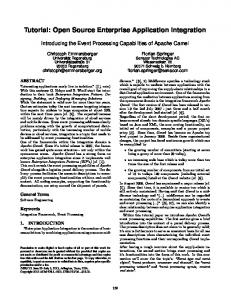
2.3.2 Redundancy Patterns There are several patterns for creating redundant J2EE server architecture for high availability and load balancing solutions. The basic concept behind these techniques is clustering. A cluster is a set of computers which all run the same J2EE application and communicate with each other to determine the set of currently active nodes and to synchronize their internal state. The incoming requests are distributed between the running nodes to provide load balancing. If a node goes down, the other nodes take over its workload. This results in higher availability, because the failure of a single node does not directly affect the availability of the services and applications. 2.3.3 Existing Development Environments Today’s development environments (such as IBM Websphere Studio and Microsoft Visual Studio .NET) focus on modeling the functionality of applications, and the generation of the source code skeletons for software components. They do not support, however, the definition and evaluation of QoS attributes such as availability and performance. The evaluation of the non-functional parameters is deferred to the testing phase of the development. The capacity design of the hardware infrastructure environment that runs the application is not supported by any automated tools; therefore designers have to manually create the deployment plan and tune the hardware infrastructure to achieve the needed availability and performance levels. 2.4 Fault Model Enterprise application server nodes consist of several layers of hardware and software components. We assume that errors can only occur in lower levels (illustrated by Figure 1), either in the hardware or in the operating system level. Errors of the higher level components can be easily and rapidly detected and repaired by the local management agent that can restart the failed component. Hardware and operating system errors cannot be repaired as fast as the higher level errors. This results in a much longer downtime. Even if the severity of the hardware errors is lower than the software errors, the overall service downtime is much higher because of the longer repair time.
Fig. 1. Application server components
88
A. Balogh, D. Varró, and A. Pataricza
Our fault model is applicable if we can suppose that the higher level software components are stable enough not to cause a significant downtime. Commercial J2EE application server software and database management software meet this requirement. As the application modules are typically generated by automatic code generators from a higher level model, such as BPEL (Business Process Execution Language), we suppose that the application components cause no errors. The fault model introduced here has several limitations. If running on a dependable, highly redundant hardware, where hardware component and operating system errors do not cause system restart (for example, in a massively parallel system) higher level software errors will be dominant in service downtime. As in most cases business software components are running on entry or medium level servers where the fault hypothesis is satisfied.
3 Modeling Technique We introduce the modeling techniques used for representing the functional and QoS aspects of the systems in the following sections. We used the standard UML Profile for J2EE for functional modeling with several extensions to allow the representation of the QoS aspects of system components. We illustrate the explained concepts with a running example. 3.1 Running Example Our example is a simple order processing and stock management system. It receives orders from customers, prints invoices and generates backorders to part suppliers if necessary. It consists of several services. The partner service is responsible for storing and retrieving the partner data, such as name, address, payment and discount options. The product service offers access to the various data of the companies’ products such as name, price, and description. The stock service manages the administration of the product’s stocking and movements. It relies on the product service. The actual stock state can be queried for a specific product, and goods movements can be administered. The accounting service is used to create invoices for customers who order goods from the company. This service relies on the partner service. The ordering service that relies on the product, the stock and the accounting services manages the incoming product orders. The backorder service is responsible for the creation of backorders to parts suppliers if a specific product runs out of stock. This service uses the product, stock and partner services. It is automatically invoked periodically and checks the stock state. Each service bean uses an entity bean to get access to business entity data. For example, the ordering service uses the OrderBean to access the data of living orders in the system. All entity beans use the same database to store their data. The services are grouped into three EJB containers and a database module. Figure 2 illustrates the deployment units of the system.
Model-Based Optimization of Enterprise Application and Service Deployment
89
«EJBContainer» partner «depends» + BackOrderService
«EJBContainer» ordering
+ PartnerBean database
+ AccountingService
«depends»
+ PartnerService
+ InvoiceBean + InvoiceItem
«depends»
«depends»
+ OrderBean + OrderingService
«depends»
«EJBContainer» product + ProductBean
«depends»
+ ProductService + StockBean + StockService
Fig. 2. Deployment units in the system
3.2 Modeling J2EE Components Modeling J2EE components in UML is standardized by several UML Profiles, for example the UML Profile for EJB [6]. The standard UML classes are extended with stereotypes and tagged values to provide information about the J2EE-specific properties of the system components. The EJB profile defines several stereotypes for marking the various types of Enterprise Java Beans. The “SessionBean” stereotypes marks the session beans, and the “EntityBean” marks the entity beans. Several other types (for example, message driven beans) and subtypes (container, or bean managed persistence) of components can be defined, but these are only necessary for the code generation, not for the QoS analysis. 3.3 Modeling Non-functional Requirements 3.3.1 Representing QoS Attributes in UML Models Non-functional requirements are out of the scope of the EJB profile described earlier; therefore these properties have to be modeled in another way. Modeling nonfunctional aspects of systems is described in UML Profile for Schedulability, Performance, and Time [7], and in UML Profile for Quality of Service and Fault Tolerance [8]. These profiles define elements for the specification of non-functional (for example, performance and availability) parameters of system components. In our architecture, the service access points are either web services (represented by stateless session beans) or session beans (either stateful or stateless). This means that the QoS attributes are defined for these components, and has to be automatically propagated to lower level ones. Other session beans and entity beans work at lower levels to provide basic services for the others and provide access to databases. • The QoS attributes that are used in our work are the expected availability and the peak workload of services. These two attributes are specified as tagged values (QOS_Availability and QOS_Workload, respectively) for the components. Our optimization method also needs the component dependencies to be defined, with the help of standard UML
90
A. Balogh, D. Varró, and A. Pataricza
dependencies. This way, our transformation can compute the needed QOS aspects of the lower level components. As the unit of deployment in J2EE is the EJB module, which is a set of Enterprise Java Beans, we need to propagate the QoS attributes of beans to these modules. EJB modules are represented by UML packages in our models. A package gets the maximal availability requirement and the sum of the peak workload of its components. These values are used in the further calculations. 3.3.2 QoS Attributes in the Example Not all services in our example have QoS attributes, because the source model contains only those attributes that are defined for the external available, complex services. The attributes for the other services will be automatically calculated by the optimizer. As mentioned before, the QoS attributes are propagated to the EJB modules. The results are illustrated in Table 1 (N/A means that no explicit constraints are defined). Table 1. Calculated QoS parameters for the EJB modules
Module name Product Partner Ordering Database
Availability 99.9 99.9 99.99 n/a
Workload 200 22 50 n/a
3.4 Modeling Available Physical Components In our scenario physical system components are server computers that can run J2EE applications. UML Components represent the server types in our model. 3.4.1 Performance Metrics There are several industrial standard benchmarks that measure the overall performance of a server system with all of its hardware and software components. One of these is the TPC-W benchmark developed by the Transaction Processing Performance Council. This test measures the performance of a web-based transactional system. As enterprise services are web services, this benchmark can be used as a reference for the overall system performance. The model of the server components has a tagged value called “performance”, which holds the number of the served requests determined by the TPC-W benchmark. This will be used to determine the capacity (maximum workload) of the server. 3.4.2 Component Costs The server components also have an associated cost value that indicates the TCO (Total Cost of Ownership) value of the server, including the cost of all hardware (processor, memory, disks, UPS, and so on) and software (OS, application server, management tools) components, and all associated services (extended warranty, onsite service) for a given period of time.
Model-Based Optimization of Enterprise Application and Service Deployment
91
The time factor depends on the desired lifetime of the service or application that is served. In case of applications with long life cycle, the basis of the calculation could be the expended life cycle of the server farm. The typical length of the lifecycle of servers is around 2-3 years. To make the cost of the possible server choices comparable, the time factor should be universal for the whole model. The components have a tagged value called “TCO” to hold the Total Cost of Ownership value. 3.4.3 Component Availability The third QoS value that is attached to servers is the availability. This attribute depends on the hardware, software, and also on the value added services offered to the specific server. Hardware suppliers specify the MTBF (Mean Time Between Failures) value for computer hardware. This can act as a starting point of availability calculation. As mentioned before, we handle only hardware and operating system errors, as the potential downtime they can cause is much higher than is case of higher level software component errors (application server or database server components), because the software components can be efficiently monitored and restarted in case of errors. If we want to achieve high availability, software errors play also an important role, as the 30-60 sec typical restarting time of a J2EE application server can also affect the availability of a critical service. In this case, the system adds extra redundancy to avoid the unavailability of service. Availability (A) can be calculated from the MTBF value and the MTR (Mean Time to Repair) by the following formula (1). A = MTBF/(MTBF/MTR) .
(1)
Availability is also attached to the server components by a corresponding tagged value. 3.4.4 Component Cardinality The last attribute of physical system components that is required for our analysis is the maximum number of available instances of a given server type. This is important if we want to deploy the needed services on an existing infrastructure. The number of the server instances is stored in tagged value “max_instances”. 3.4.5 Physical Components in the Sample System In this sample system we have three different server machines that can be used for serving the application. The performance and availability data of the servers are approximate values as we do not know the exact service contracts data and resale prices for these machines. The first configuration is an entry level Intel x32 server that can process 90 requests per minutes and has an availability of 97%. Its TCO is 2500 Euros. The second configuration is a more robust Intel x32 server that can process 170 requests per minutes and has an availability of 98%. Its TCO is 3700 Euros. The third configuration is a robust multi processor PowerPC server with redundant components and can process 1400 requests per minutes and has an availability of 99.9%. Its TCO is 18000 Euros.
92
A. Balogh, D. Varró, and A. Pataricza
4 The Optimization Workflow We introduce our code generation and architecture synthesis methods in this section. We have been used our general-purpose model transformation system for the implementation of the required transformations and code generation scripts. 4.1 Architecture Synthesis The process synthesis consists of two main steps (see Fig. 3). The first step is the transformation of the UML model of the system to a special format that can be imported to the optimization program. The program that is used for the synthesis is the second step of our workflow. The result of the process is the recommended architecture of the system. In parallel with the optimization, the source code of the system components can also be generated with commercial code generators or the VIATRA 2 framework.
model transformation UML Model
QoS data of service and servers
optimization Optimized deployment structure
Source code code generation
Fig . 3. Model processing workflow
4.1.1 Model Transformation The first basic step of the transformation is the propagation of the bean QoS values to the EJB modules as described earlier. Each EJB module inherits the maximum availability and aggregates the performance value of its beans. The second step is to propagate the bean dependencies to the modules. An EJB module depends on an other one if at least one of its beans depends on one of the beans in the other container. After all QoS attributes and dependencies have been propagated to EJB containers, the transformation program generates the input file for the optimization program by the traversal of the UML package structure. It prints out the defined capacity and availability requirements and dependencies for every UML package that is marked with the stereotype EJBModule. 4.1.2 Deployment Optimization We developed a simple command-line application that computes the optimal deployment pattern for the input system. It takes the input file with the system services and available hardware components and generates the optimal system configuration as output. The arrangement of EJB modules between servers is a special optimization task. There are finite number of resources and finite number of software modules that must
Model-Based Optimization of Enterprise Application and Service Deployment
93
be related to each other. There are also several special constraints that describe the QoS constraints and dependencies of the components. The goal of the optimization process is to minimize the overall system cost while providing the necessary system availability and capacity. 4.2 Implementation Technology We have developed VIATRA [9], our general model transformation system, in order to support the dynamic, multilevel metamodeling features of VPM [10], and generic/meta transformations [11]. The main intended usage of our framework is dependability evaluation and optimization of business process workflow models and UML models. A source user model (which is a structured textual representation such as an XMI description of a UML model exported from a CASE tool) is imported into the VPM modelspace. Transformation specifications can be constructed by combining graph transformation [12] and abstract state machine [13] rules. These rules can be created within the framework or in a UML tool using a special profile (and, in the future, using the QVT standard). The rules are then executed on the source VPM model by the generic (higherorder) VIATRA rule interpreter in order to yield the target (VPM) model. Finally, the target model can be serialized into an appropriate textual representation specific to back-end tools. The VIATRA 2.0 framework is implemented as a set of plugins for the Eclipse framework [14] that is a widely used open-source system development and modeling framework.
5 The Mathematical Model for Optimization Optimization, in general, means a method that searches a point in the problem space that satisfies the defined constraints, and the objective function has a maximum (or minimum) value. Several special optimization problem classes have been defined, for example the traveling agent problem. 5.1 Our Optimization Problem 5.1.1 Initial Steps The first step of the optimization process is the calculation of the aggregate workload of software modules. The developer only has to specify the direct workload for a specific container (the actual requests from clients) but the capacity needs to depend also on the indirect workload (calls from depending services). In our simple model, we suppose that a dependency represents a single call to the target service. The calculation of aggregate workload is a recursive expression that calculates the workload as a sum of the direct workload and the additional workload of depending services (expression (1)). The depends(i) is a set of services that depend on service i.
94
A. Balogh, D. Varró, and A. Pataricza
Workload(i) = Capacity_ need(i) +
∑ Workload( j) .
j∈depends(i )
(1)
5.1.2 The Workload Constraint The workload constraint means that the aggregated capacity of all deployed software modules on a specific machine must not exceed the capacity of the machine. A further tuning possibility is to define a saturation factor (SF) that specifies the maximum rate of workload on machines. Expression (2) specifies the workload constraint.
∀m ∈ HW : Capacity(m) ∗ SF ≥
∑Workload (s)
s∈deployed ( m )
(2)
5.1.3 The Availability Constraint The availability constraint specifies that the actual availability of each service must be at least as high as the required availability. The actual availability of a service can be calculated from the availability of the hardware that runs the service and the availability of depending services. Expression (3) specifies the availability constraint. A service is available if the hardware it is running on is available and all the required services of the specific service are available. We suppose that if a hardware unit is running then all services deployed on it are running as well. We also suppose that all hardware nodes are independent, which means that all of them have their own uninterruptible power supply, disk subsystem, and so on.
A act ( i ) = P ( HW available ∧ All needed services available ) =
∏ P ( HW
= P ( HW available ) ∗
available ) =
all HW running required service
= A HW ( i ) ∗
∏A
HW ( j ) ∀ j , HW ( j ) running needed service
(3)
∀ i ∈ services : A act ( i ) ≥ A required ( i )
5.1.4 The Objective Function The objective function of the optimization process is the overall cost of the system, as described by expression (4). The total cost of the system is the aggregation of the product of the cost and the actual number of the defined hardware components.
TCO System =
∑ TCO ( m ) ∗ number
m ∈ HW
_ used ( m ) .
(4)
5.1.5 The Solutions A solution of the problem is a mapping between computers and software modules that satisfies all constraints. Solutions are computed by a backtrack algorithm that tries to build the mapping step-by-step while maintaining the constraints. The optimal solution is the solution that has the lowest overall cost.
Model-Based Optimization of Enterprise Application and Service Deployment
95
5.1.6 Additional Steps If the required availability or performance levels cannot be reached using the basic hardware types defined in the model, the optimizer applies the J2EE redundancy patterns for the design. This means that the program creates clusters from the basic hardware nodes to raise the availability and performance of a server. If the availability requirements do not allow single point of failures in the system, the developer can specify that only redundant arrays of machines can be used during architecture synthesis. This means that the program creates clusters even if the performance and availability of a single computer could satisfy the needs of the services. The capacity of a cluster consisting of several nodes can be lower than the sum of the capacity of the nodes. That is because various synchronization messages and algorithms that are running on nodes. The typical value of performance loss depends highly on the actual server software, but it can be measured or taken from server benchmarks. Our tool supports the definition of a “performance loss percent” that is subtracted from the sum performance of the cluster nodes. If the services only use stateless session beans and entity beans, this loss is negligible in most cases. More components (EJB containers) can be deployed on the same server if the hardware has enough capacity for running all the services. This ensures that the workload of the servers will be nearly equal, and the hardware costs will be minimized. The optimization program calculates the optimal configuration of services and hardware nodes using the explained equations and constraints. The output of the program is a list of services and the associated hardware nodes. This defines the suggested configuration of the system. 5.2 Optimization Results of the Example The optimal configuration with the original QoS attributes is to create a four node cluster from the medium level server. This configuration has an availability of more than 99.99999% and a total cost of 14800 Euros. All services are deployed to this single cluster. If we suppose that the business grows very rapidly and the workload grows to the tens of the original. The optimal architecture in this case is to create a two node cluster form the third server that runs the database, and the partner modules, an other two node cluster from the third type that runs the product module, and a three node cluster formed from mid range servers that runs the ordering module. The total cost of the system is 83100 Euros. This is 5.6 times more than the original, but offers 10 times more performance. This shows that a few of large but expensive servers can be used for serving heavy workloads, but for small workloads clusters built up from cheap servers can be used successfully.
6 Related Work The model-driven analysis of QoS attributes of component-based systems under design has recently become a hot research topic. Primary focus is usually put on performance issues such as, e.g., in [17,18,19]. The early assessment of traditional de-
96
A. Balogh, D. Varró, and A. Pataricza
pendability attributes is carried out in [20,21]. In most of these papers, a traditional transformation-based approach is followed where the QoS parameters are generated from a higher-level initial model (semi-)automatically. In contrast to these approaches, we focused on availability and cost parameters of deployment. In [22], the authors define a method for dependability analysis of systems based on UML models. The basic idea behind that method is the transforming UML models to Timed Petri Nets (TPN). The starting point of the method is the architectural level model, so it works on a static infrastructure and does not modify the systems architecture. In [23], the authors define a method for dependability analysis of systems based on UML models. The basic idea behind that method is the transforming UML models to Timed Petri Nets (TPN). The starting point of the method is the architectural level model, so it works on a static infrastructure and does not modify the systems architecture. Probably, the most closely related work is that work of Bastaricca et al. [15], where the authors describe two deployment optimization methods that can be used in a distributed component-based environment. Both algorithms do the optimization of the deployment, but they work on a static infrastructure that cannot be modified. This way, they cannot be used for infrastructure planning, only for deployment on existing hardware environments. Moreover, the algorithms do not optimize for TCO, but for network utilization.
7 Conclusion and Future Work Enterprise services play an important role in today’s business environment. Besides the functional requirements the quality-of-service attributes are also more and more important. The most commonly used development environments do not support the handling of QoS attributes like availability and performance requirements of services. In the paper, we introduced an approach to generate the optimal deployment plan for a set of enterprise services based on the UML model of the system and a hardware specification catalog. Our method ensures that the deployed system will keeps the availability and capacity constraints defined by the system model. The current method is applicable only in design time, thus further improvements has to be made to extend its capabilities to allow the runtime reconfiguration of the systems. This will enable the automatic tuning of system availability and performance reflecting to the changes in the environment (the growth of the workload or the permanent fault of a server node). To achieve this functionality, our optimizer need to be connected to a systems management software such as IBM Tivoli [16] that collects runtime information about the usage statistics and state of services and hardware nodes. Further research has to be done for discovering methods to a finer granularity workload prediction that relies on the behavioral model of the services (for example it discovers that a service uses another several times). Other methods has to be devel-
Model-Based Optimization of Enterprise Application and Service Deployment
97
oped to predict the relative weights of service executions to distinguish more complex services as they cause higher workload as simple services.
References 1. The Object Management Group, MDA Information Portal, http://www.omg.org/mda 2. The Object Management Group, UML2 Superstructure specification, August 2003 http://www.omg.org/ 3. Steve Graham et al, Building Web Services with Java: Making sense of XML, SOAP, WSDL and UDDI, 2002. 4. Microsoft, IBM, BEA, et al. Business Process Execution Language for Web Services Specification. 5 May 2004. 5. Sun Microsystem. Java 2 Platform Enterprise Edition Specification v1.4. November 2003. http://java.sun.com/j2ee 6. Jim Conallen, Building Web Applications with UML, Addison-Wesley, 1999. 7. The Object Management Group, UML Profile for Schedulability, Performance, and Time Specification, January 2005. 8. The Object Management Group, UML Profile for Modeling Quality of Service and Fault Tolerance Characteristics and Metrics, September 2004. 9. D. Varró, G. Varró, and A. Pataricza. Designing the automatic transformation of visual languages. Science of Computer Programming, vol. 44(2):pp. 205-227, 2002. 10. D. Varró, A. Pataricza. VPM: A visual, precise and multilevel metamodeling framework for describing mathematical domains and UML, Journal of Software and Systems Modeling vol. 2 pp. 187-210, 2003. 11. D. Varró, A. Pataricza. Generic and Meta-Transformations for Model Transformation Engeering. In Proc. UML 2004: 7Ih international Conference on the Unified Modeling Language 12. H. Ehrig, G. Engels, H.-J. Kreowski, and G. Rozenberg (eds.). Handbook on Graph Grammars and Computing by Graph Transformation, vol. 2: Applications, Languages and Tools. World Scientific, 1999. 13. E. Börger and R. Stark. Abstract State Machines. A method for High-Level System Design and Analysis. Springer, 2003. 14. The Eclipse Framework. http://www.eclipse.org 15. M. Bastarrica et al. Two Optimization Techniques for Component-Based Systems Deployment, Proceedings of the Thirteenth International Conference on Software Engineering and Knowledge Engineering, pp. 153-162, 2001 16. IBM Corporation, IBM Tivoli Software Homepage, http://www.ibm.com/software/tivoli/ 17. S. Chen, I. Gorton, A. Liu, and Y. Liu, Performance Prediction of COTS Componentbased Enterprise Applications, CBSE5, Orlando, Florida, USA, May 2002. 18. A. Bertolino, R. Mirandola Software performance engineering of component-based systems. Proceedings of the Fourth Int. Workshop on Software and Performance, pp. 238 – 242, 2004. 19. J. Skene, W. Emmerich. Model Driven Performance Analysis of Enterprise Information Systems, In Proc. of the Int. Workshop on Test and Analysis of Component Based Systems, Warsaw, Poland, April, ENTCS vol. 82, num. 6, 2003. 20. V. Grassi. Architecture-based Dependability Prediction for Service-oriented Computing. In Proc. of WADS 2004,
98
A. Balogh, D. Varró, and A. Pataricza
21. V. Cortellessa, H. Singh, B. Cukic: Early reliability assessment of UML based software models. Proceedings of the Third Int. workshop on Software and Performance, pp. 302 – 309, ACM Press, 2002. 22. István Majzik, András Pataricza, and Andrea Bondavalli. Stochastic dependability analysis of system architecture based on UML models. In Rogerio de Lemos, Cristina Gacek, and Alexander Romanovsky, editors, Architecting Dependable Systems, volume LNCS-2677, pages 219-244. Springer, 2003. 23. István Majzik, András Pataricza, and Andrea Bondavalli. Stochastic dependability analysis of system architecture based on UML models. In Rogerio de Lemos, Cristina Gacek, and Alexander Romanovsky, editors, Architecting Dependable Systems, volume LNCS-2677, pages 219-244. Springer, 2003.