deadlocks. In particular we have concentrated on developing techniques that allow the realistic simulation of web and e-commerce applications, as usability is a ...
Model-based Simulation of Web Applications for Usability Assessment Robert Chatley, Jeff Kramer, Jeff Magee, Sebastian Uchitel Dept of Computing, Imperial College London {rbc,jk,jnm,su2}@doc.ic.ac.uk Abstract In this paper we discuss an approach for simulating the behaviour of interactive software systems, before starting on any of the actual implementation, based on a model of the system at the architectural level. By providing a mock-up of the final user interface for controlling the simulation, it is possible to carry out usability assessments of the system much earlier in the design process than is usually the case. This means that design changes informed by this usability assessment can be made at this early stage. This is much less expensive than having to wait until an implementation of the system is completed before discovering flaws and having to make major changes to already implemented components. The approach is supported by a suite of cooperating tools for specification, formal modelling and animation of the system.
1. Introduction In recent years, there has been increasing regard for usability as a quality attribute for software. Techniques have been developed by which the usability of systems can be assessed [1][2], however these techniques often involve activities such as interviewing users, or recording their use of the system with a video camera. Using them therefore requires a working implementation of the system and a representative user. This means that usability assessment and subsequent improvement may only be carried out late in the development process. At this stage it is very expensive to go back and make major changes to the design[3]. We present a technique for modelling the system at the architectural level, including its interaction with the user, and connecting this to a realistic mock-up of the user interface. This allows some traditional usability assessment techniques to be applied much earlier in the design process, once the architecture has been determined, but before detailed design and implementation have started. It also allows for checking properties of the system, for instance finding possible
deadlocks. In particular we have concentrated on developing techniques that allow the realistic simulation of web and e-commerce applications, as usability is a key factor in the success of these types of application[11]. The remainder of this paper describes the approach in detail, the supporting tools and examples of their use. The input to our modelling and simulation technique is a set of scenarios describing interactions between different components (including the user) of the system. In previous work on scenarios we have developed techniques for analysing formal models built from sets of scenarios described in the form of Message Sequence Charts (MSCs) [4]. Here we use a set of MSCs to specify behaviours of the user and system. From these we synthesise a behaviour model which drives the simulation.
2. Background The Labelled Transition System Analyser (LTSA) tool allows the construction and checking of models of finite state processes. This tool, which is described fully in [5], allows us to build models of the behaviour of complex systems which are amenable to formal analysis in the form of labelled transition systems (LTS), and to check properties of these models mechanically. We have extended this tool to allow system behaviour to be specified by means of sets of scenarios described in the form of MSCs. This work is described in [6]. Using these techniques, we are able to build models of the behaviour of systems, which include the user, built up from scenarios gathered during the requirements elicitation process. In this way we can model and investigate the interactions between the system and the user. In order to make it possible to test the quality of the user’s experience of the system based on the model, some sort of animation needs to be provided to allow the user to interact with the model through an interface which at least approximates that which they would use in the final system. Animation has previously been used to make it easier to interpret the meaning of traces returned from model checking[7]. A trace to deadlock for example may
be illustrated in the problem domain by replaying the relevant sequence of actions as a graphical animation. In order to simulate web applications, and to give a more accurate representation of the experience of using a web application, we have developed a new animation technology allowing users to interact with the model through the familiar interface of web pages displayed in a standard web browser. This technology is described in more detail in Section 4.
3. Animating Models The behaviour of a model can be interactively explored using the LTSA tool. The output of such an execution is essentially a trace of action names. Each action is the abstract representation in the model of an input or output of the proposed system [5]. One of the features provided by the unextended LTSA is the ability to run or to step through a trace of possible actions, and to see the resulting state changes reflected in the state machines. LTSA can display graphically state machines reflecting the LTS for each separate component or for a composed system. The current state and the last transition made are highlighted on the display. The user can trigger any of the currently available actions by selecting them from a dialog box, causing a transition to occur. A difficulty arises in interpreting the meaning of traces in relation to the original problem domain. Even when the meaning is clear to the model designer, the problem of communicating model to non-technical stakeholders of a system remains. Because we want to explore and assess the usability of the system based on these behaviour models, we need to develop techniques that enable us to convey the meaning of the model, in terms of the actual system that it is intended to represent, to an end user. As discussed in [7], there is a lot to be gained from using graphic animations to communicate the results of analysing formal models of systems. One example of an animation technique which can be used with LTSA is SceneBeans[8]. SceneBeans is a Java framework for building and controlling animated graphics. It removes the drudgery of programming animated graphics, allowing programmers to concentrate on what is being animated, rather than on how that animation is played back to the user. SceneBeans is based upon JavaBeans and XML. Its component-based architecture allows application developers to easily extend the framework with domain-specific visual and behavioural components.
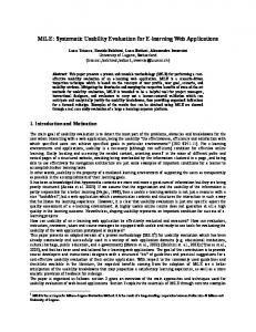
4. Simulating Web Applications Scenebeans has been used to present a graphical representation of how components interact in models of complex concurrent systems, for example switching between channels on a modern television set. However, using this particular technology to animate the model, it is difficult to produce an interface that accurately represents the type of interface users are accustomed to for a web or e-commerce application, namely that of web pages in a web browser. Therefore, it is difficult to use such a simulation for usability testing and gain an accurate idea of users’ responses to the actual system. In the television example, there are sufficient differences between the way that a user would interact with the on-screen representation of a remote control and the way that they would use a physical handheld remote control to render any usability measurements taken using the simulation fairly meaningless. To give an accurate idea of the usability of the system, a mock-up of the eventual user interface needs to be provided that is much closer to what the user will actually experience. To attack this problem in the arena of web and ecommerce applications, we have developed a new animation technology, which allows the user to interact with the model of the system by means of clicking on links and buttons in a web browser. The LTSA tool was extended so that it can provide an interface to the model through a set of web pages which can be viewed in a standard web browser. This extra functionality was provided by writing a plugin to be used with LTSA’s extension mechanism, as with the Message Sequence Chart extensions. The benefits of the approach to simulation given here as compared to, for instance, that taken in [12] are that our simulation tools work with our existing behaviour modelling tools without having to change the representation in any way, and that the appearance of the interface to the simulation can easily be made to reflect a designer’s proposal for the look of the final system. The web animator plugin allows us to associate fragments of HTML with different possible actions. These can be hyperlinks, buttons or any other interactive element commonly found on web pages. The plugin will dynamically compose a web page from these fragments and serve it to a web browser to display. The user can then click on any of the buttons or links in the browser to trigger a transition in the LTS. The basic architecture of the Web Animator is shown in Figure 1. The plugin adds a mini webserver to the LTSA so that it can communicate with a standard web browser by means of the HTTP protocol. The LTSA produces an XML document describing the available transitions each time that a new state is reached. An XSLT[9] transformation is applied to this XML
document based on an XSL stylesheet. This stylesheet describes a transformation from XML to HTML which defines the visual appearance of the web pages. This HTML is then sent over the network via HTTP to the browser where it is rendered. When the user is presented with such a webpage, they can click on any of the links or buttons on the page, which will cause the browser to send an HTTP request back to the server. The server analyses this request to detect what action the user has requested and triggers an appropriate transition in the LTS. Extra decision logic has been added so that it is possible to make a distinction between actions that are carried out by different parties. This allows us to distinguish between actions performed by users and those that are carried out by components of the system without any user intervention. We call these respectively “user actions” and “system actions”. An external XML file is used to configure which actions are to be classed as system actions and which as user actions. If in any state there are no actions available to the user, only system actions, the tool will pick a system action to perform and continue to execute system actions until a state is reached where there is a user action available. On reaching such a state control is returned to the user and the user can choose which of the actions available to them to perform next. It is possible to control the way in which the tool selects an action from the available system actions in any state by including extra information in the XML configuration file. Boolean expressions can be encoded in the XML, which can be used to make decisions on which system action to perform. These
expressions can also test data which may have been input by the user through fields on the web page interface. For example, a typical scenario might be that of logging in to a website with a username and password. Depending on whether the username and password are entered correctly, the next page that the user sees will be different. This can be modelled by having a choice of two system actions authenticate and reject. If the username and password match the expected values, the system should perform the authenticate action, otherwise it should perform the reject action and ask the user to try again. If the simulator has no extra information to guide its choice, it simply makes a random selection from the available system actions. The visual appearance of the web pages is described in an XSL stylesheet. This is a standard way of expressing a transformation from XML to another data representation, in this case HTML. This technique is itself commonly used in web and e-commerce applications. Because the output is standard HTML, we can achieve an interface which is very close to that that might be used in the final system. The separation of concerns, separating the definition of the visual representation and the extra decision logic from the scenarios and the specification of the behaviour model, means that we can achieve a better simulation as the different parts of the model can be worked on by different people, for instance a graphic designer could produce the visual representation without having to learn about MSCs or behaviour models. We can also change the visual representation and which actions are system or user actions independently of the behaviour model, and so
LTSA LTS Model
List available actions
Web Browser
Web Animator Plugin HTML (HTTP) XML action list
Render HTML
XSL Transformer
User clicks
Do transitions
Decision logic
Process request
HTTP request
Figure 1 : Basic architecture of the web animator plugin.
Contact server
do not have to recompile the model to make these changes. The fact that the web animator serves web pages by means of the standard HTTP protocol means that we can run the system over a network, and so can observe the model on one computer whilst running the browser with the user interface on another. This greatly increases the exibility of the simulation environment.
5. Case study: LogicDIS eSuite The eSuite product developed by LogicDIS (a Greek company who is one of the commerical partners in the STATUS1 project) is a system that allows access to an ERP (Enterprise Resource Planning) system, through a web interface. The system employs a tiered architecture commonly found in web applications. The user interfaces with the system through a web browser. A web server runs a Java servlet and some business logic components, which communicate with the ERP. In this case study we first give examples of scenarios describing possible uses of the system, and the interactions between system components.
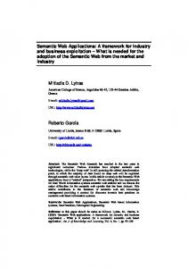
Figure 2 : An example scenario “Login” from the eSuite model. Figure 2 gives an example of a scenario from the eSuite model. The four components that take part in the scenario are shown as instances. They are the user (which corresponds to a human with a web browser, messages originating from the user are sent when the user clicks a button in the browser), the servlet (software running on the web server which receives requests from the browser), the business logic (BizLogic) at the heart of the eSuite
1
STATUS is an ESPRIT project (IST-2001-32298) financed by the European Commission in its Information Society Technologies Programs
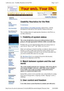
application, and the ERP, which is effectively treated as an external database. The sequence of messages in Figure 2 show what happens when a user successfully logs in to the system. A chain of messages cascades through the tiers of the architecture and information comes back, finally resulting in an HTML page being displayed to the user informing them that they are now logged in to the site. This is just one of a large number of possible scenarios that can occur. For each of the scenarios that we are interested in, we construct a basic MSC like this. We can then describe the sequence in which these scenarios can occur by using a high level message sequence chart (hMSC). Figure 3 shows part of the hMSC for the eSuite model. It shows how scenarios can occur in turn (the completion of one enabling another to be entered), or in iteration as is the case with FailedLogin (a user can repeatedly attempt to log in, get their password wrong and try again).
Figure 3 : Part of the hMSC for the sSuite model displayed in the LTSA tool. The specification consists of one hMSC and a number of bMSCs. In the tool, each bMSC has its own tab, as does the hMSC. Double-clicking on a scenario in the hMSC will drill down, opening a detailed view of the scenario as a bMSC. From this set of message sequence charts, we use the tool to generate a textual description of the system in the FSP process calculus[5]. This can then be compiled into a set of labelled transition systems, which we can again view graphically. Figure 5 shows a graphical representation of the LTSs corresponding to the different components of the system. The top diagram in the tool represents the user. It contains only the states and actions
that pertain to the user. The highlighted states show the current position in each component’s state machine at a point in the middle of a simulation. To determine which actions should be controlled by the user during the simulation, and which were internal system actions, an XML configuration file was written detailing user and system roles. A fragment of the configuration file is shown in Figure 4. It defines the actions that are available to the user, and the conditions under which verified (a system action) can be performed, in this case when the login name and password match the expected values. enterPwd search orderHeader orderDetails itemDetails back
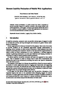
Figure 4: A fragment of the XML configuration file. An XSL stylesheet with templates corresponding to the various possible user actions was also written. Images were supplied by LogicDIS which reflect the graphical appearance of their application. These are easily incorporated into the interface using standard HTML, and our tool allows us to provide standard headers and footers for each genrated page. It is also possible to use cascading style sheets to apply a custom style to all generated pages. These are commonly used in the development of web applications to achieve a consistent look across all pages, and provide us with an easy way of reflecting the envisaged design of the finished application in the simulation. Figures 6, 7 and 8 show mock-up interface screens from the simulation as the user walks through logging in to the eSuite application and searching for an order. As can be seen from the pictures, we have managed to replicate the look of a web application interface in the simulation very closely by using standard web page features like text-boxes, buttons and hyperlinks. The inclusion of graphics and stylesheets from LogicDIS help to reflect the look of a finished application, and show how the visual aspect of the simulation is separated from the behavioural part. Using these images, produced by a specialist designer, is a simple matter of including a couple of lines of standard HTML in the XSL stylesheet.
Figure 5: LTSs corresponding to the different system components, displayed in LTSA. The user can interact with the simulation of the system in exactly the same way as they would with a real web based system, by clicking on links and buttons in the web browser. Transitions occur in the underlying LTS model, unseen by the user, and another web page is returned to them. In this way we can allow the user to experience interacting with the system, and find out whether the series of interactions they go through to perform tasks, or find things on a website, is easy to learn, efficient to use, consistent, predictable and so on, using traditional usability assessment techniques, but using the simulation rather than the finished system.
Figure 6: A simulation interface screen displayed in a web browser, showing the login screen.
If it is felt that the usability of the system could and should be improved, suitable changes can then be made to the design of the way that the user interacts with the system simply by making changes to the MSC specification and recompiling the model, after which the simulation can be run again. At this early stage in the development process it is still cost effective to make these changes, as development effort has not yet been spent on implementing a detailed design.
Figure 7: When the user has logged in they can perform a search.
6. Conclusion We have shown that by building a behaviour model for a system from a set of scenarios, and linking it to a suitable animation, a user can interact with a simulation of a system with a similar experience to using the real application. Simulations can be built which reflect interaction with a real system to the extent that they are suitable for performing usability assessments. Scenarios in the form of MSCs provide an easy method for describing individual system behaviours from which we can synthesise a formal model. This model is then used to constrain the behaviour exhibited in the simulation. We presented a new animation tool which allows an interface in the form of a set of web pages to be attached to a behaviour model in the form of a labelled transition system. By harnessing standard web protocols, the tool allows a user to interact with a simulation of a web application using a standard web browser interface. This allows us to provide a realistic simulation. By separating the visual aspects of the simulation from the behaviour model we allow each to be developed separately by specialists and then easily combined. We presented a case study in which we created a simulation of an existing e-commerce application, starting with a set of scenarios. With relatively little effort we were able to recreate the look and feel of the original application’s interface in our simulation. Using this technique affords us the possibility of performing usability tests early in the development process. Identifying usability weaknesses at this stage allows for significant changes to be made to the design of a piece of software without incurring great expense. Traditionally the results of usability tests have lead only to fairly cosmetic changes to the interface of systems, concerning the display and layout of data. Changes to the way that the user interacts with the system may require much greater change to a system, possibly at the architectural level. For instance, the ability to undo actions cannot be added as a last minute feature, it must be factored into the architecture at an early stage [10]. Early detection of usability problems and possible improvements using the simulation techniques described here can help us to engineer for usability from the start of the development process.
7. Future Work Figure 8: The results of a search operation are displayed.
A feature of web applications not explored here is the possibility that more than one user is using the system at the same time. In future work we hope to simulate the effect on the system of multiple concurrent users, to see whether the action of one user may affect another user’s
experience of the system, and whether this may be the cause of unexpected behaviour. By combining this simulation approach with some work on stochastic modelling, it would be possible to introduce effects such as non-deterministic time delays in certain parts of the system (for instance a delay during server processing before a page is returned to the client). Introducing these effects could lead to even more realistic simulations. If there are properties of systems which we can categorise as being undesirable from a usability perspective, it would be interesting to try to detect these using a model checking algorithm. Another extension of this work might be to use the simulation interface to elicit further scenarios and elaborate a partial model of the system as part of a usercentred design process.
8. Acknowledgements We gratefully acknowledge the support of the European Union under grant STATUS (IST-2001-32298), and the partners working on the STATUS project.
9. References [1] Preece, J., Y. Rogers, H. Sharp, D. Benyon, S. Holland, T. Carey. Human-Computer Interaction. Addison Wesley, 1994. [2] Constantine, L.L., L.A.D. Lockwood. Software for Use: A Practical Guide to the Models and Methods of Usage-Centered Design. Addison-Wesley, New York, NY, 1999. [3] Brooks, Jr., F.P., 1995: The Mythical Man-Month: Essays on Software Engineering, Twentieth Anniversary Edition, Reading, MA: Addison-Wesley [4] S. Uchitel, J. Kramer and J. Magee. “Negative Scenarios for Implied Scenario Elicitation”, Proceedings of 10th ACM SIGSOFT International Symposium on the Foundations of Software Engineering (FSE'02) [5] Magee J., and J. Kramer, Concurrency – State Models and Java Programs. John Wiley & Sons, March 1999 [6] S. Uchitel, R. Chatley, J. Kramer and J. Magee. “LTSAMSC: Tool Support for Behaviour Model Elaboration Using Implied Scenarios”, Proceedings of TACAS 2003 [7] J. Magee, N. Pryce, D. Giannakopoulou and J. Kramer, “Graphical Animation of Behavior Models” [8] N. Pryce and J. Magee, “SceneBeans: A Component-Based Animation Framework for Java” [9] J. Clark, “XSL Transformations (XSLT) Version 1.0”, http://www.w3.org/TR/xslt
[10] L. Bass, B. John, J. Kates. “Achieving Usability Through Software Architecture”, CMU/SEI Technical report 2001 [11] Nielsen J., Designing Web Usability, New Riders Publishing, Indianapolis, 2000 [12] A. Egyed and D. Wyle, “Statechart Simulator for Modelling Architectural Dynamics”, Proceedings of the 2nd International Working Conference on Software Architecture (WICSA), Amsterdam, 2001.