software testing tool, Google Test. The results ... The literature of testing performance of autonomous. robots mostly .... guide the test-generation algorithms, and tools that generate. supporting ... best trajectory, the population is continuously being modiï¬ed ...... open-source multi-robot simulator,â in IEEE/RSJ IROS, 2004.
Model-based Testing of Real-time Adaptive Motion Planning (RAMP)* Mahmoud Abdelgawad1 , Sterling McLeod2 , Anneliese Andrews1 , and Jing Xiao2
Abstract— It is a practically challenging problem to test the functionality of autonomous systems and assess their performance in environments with unknowns and unpredictability. Existing testing techniques are designed heavily based on testers experience and hardly take into account all scenarios. This paper applies a model-based testing technique to evaluate the functionality and performance of a Real-time Adaptive Motion Planning (RAMP) system. First, RAMP components and their interactions are tested. Next, the whole RAMP system is tested against mobile obstacles of unpredictable motion. The model-based testing technique models the behaviors of RAMP components and the mobile obstacles with a Communicating Extended Finite State Machine (CEFSM). The behavior models are then leveraged to generate Abstract Behavioral Test Cases (ABTCs). These ABTCs are subsequently transformed by test data into executable test cases. The generated executable test cases are further applied to a RAMP implementation based on the Robot Operating System (ROS) and executed with the software testing tool, Google Test. The results demonstrate an effective use-case of applying a systematic software testing technique to the evaluation of real-time robotic systems.
I. I NTRODUCTION The literature of testing performance of autonomous robots mostly covers computer-based simulation and test fields/arenas. Jacoff et al. [1] introduced a standard for designing and evaluating test arenas (Reference Test Arena for Autonomous Mobile Robots). The test arenas consist of collapsed structures that are designed from buildings in various stages of collapse. Such test arenas provide physical fidelity but they are costly and limit repeatability. Laval et al. [2] recognize that tests should be repeatable, reusable, and automated as much as possible. The authors conducted experiments on two robots with software based on the Robot Operating System (ROS) [3] in instrumented environments. to show that test repeatability is important to assess mobile robot performance. Pepper et al. [4] illustrated a computer-based simulation technique for evaluating Search and Rescue (SaR) robots using USARSim, a robot simulation tool. The computer-based simulation is flexible, repeatable, and accurate compared to physical test fields/arenas, but it lacks physical fidelity. Koenig and Howard [5] introduced a high fidelity outdoor dynamics simulator Gazebo. However, it limits physical fidelity due to models of soil, sand, grass, and other pliable surfaces *This work was supported, in part, by NSF IUCRC grant #IIP-1439693 to the University of Denver and #IIP-1266162 and #IIP-1439695 to University of North Carolina at Charlotte. 1 The authors are with Department of Computer Science, University of Denver, Denver, CO 80208, USA {abdelgaw,
andrews}@cs.du.edu 2 The authors are with Department of Computer Science, University of North Carolina at Charlotte, Charlotte, NC 28223, USA {smcleo12,
xiao}@uncc.edu
not being addressed that can impact robot motion. Theoretically, both techniques (test fields/arenas and computerbased simulation) cannot fully realize criteria-based testing [6] because test scenarios are designed based on testers’ experience. Moreover, these techniques are impractical for testing the interactions between system components. The Real-time Adaptive Motion Planning (RAMP) system [7,8] is to enable a robot to operate in an environment with moving obstacles of unforeseen motion through online simultaneous planning and execution of robot motion to achieve its goal while avoiding moving obstacles. RAMP consists of various components (i.e., nodes) that run concurrently. A component in software engineering is any module that encapsulates related functions and/or data. In the RAMP framework, there are components for coordinating control and planning cycles, generating trajectories, evaluating trajectories, modifying paths, sensing, and controlling the robot. The interactions among these components must occur in correct temporal order and duration regardless of uncertainty in order to have successful robot motion. Testing the interactions among these components poses challenges due to their time constraints, concurrency, and the large number of possible behaviors. Such challenges are representative of real-time, sensing-based algorithms for autonomous robots. It is also practically very challenging to test how the RAMP system performs in handling the interactions between the robot and those obstacles with unforeseen, arbitrary motion, due to their uncertainty and concurrency, as well as the large number of possible behaviors of the obstacles during the interactions. To address these challenges, this paper demonstrates the use of a systematic Model-based Test (MBT) technique [9, 10] to generate testcases that are effective to evaluate the correctness and performance of interactions among RAMP components as well as the interactions between RAMP and environmental obstacles. This MBT technique represents the testcases as graphs, allowing graph-coverage criteria to be used to generate complete coverage of test paths. This type of testing framework for autonomous robots is necessary in order to avoid relying only on ad hoc test scenarios. Such capability of systematic testing is essential to building robust systems for many autonomous robotic applications. The remainder of this paper is organized as follows. Section II presents a brief description of relevant concepts to MBT and a brief review of RAMP system. Section III presents the model-based testing technique. RAMP components integration testing is described in Section IV. RAMP system testing is introduced in Section V. Test execution, functional evaluation, and performance assessment of the
RAMP system and its components are presented in Section VI. Section VII draws conclusions. II. BACKGROUND The following briefly describes relevant concepts in model-based testing and reviews the RAMP system and its components. A. Model-based Integration Testing According to Dias-Neto et al. [11], Model-Based Testing (MBT) uses various models to automatically generate tests. MBT is practical for all software testing levels, including unit testing, component integration testing, and system testing [6]. MBT includes three key elements: models that describe software behaviors (i.e., test models), coverage criteria that guide the test-generation algorithms, and tools that generate supporting infrastructure for the tests. Lill et al. [12] use Coloured Petri Nets (CPNs) to build a test model for testing factory robots that carry a load from one place to another. Guan and Offutt [13] introduce a MBT technique for testing component integration in realtime embedded systems (RTES). They use Unified Modeling Language (UML) sequence diagram to illustrate exchanging messages between components. A Finite State Machine (FSM) is a technique used to model state transitions in a system. An FSM is defined by the set of all possible states and transitions in a system. Transitions are triggered by events, and a transition function brings the system from the current state to a new state. In an Extended Finite State Machine (EFSM) [14], transitions between states occur when a set of trigger conditions are satisfied. Further, EFSMs introduce output actions, which are instructions to be run as the system transitions out of a state. Adding communication channels between EFSMs results in a Communicating Extended Finite State Machine (CEFSM). Thus, a CEFSM can be used to model a system that consists of several processes modelled as EFSMs. An advantage of this is that a CEFSM can model orthogonal states of a system in a flat manner and does not need to compose the whole system in one state [15,16]. B. Coverage Criteria Coverage criteria are used to generate inputs for tests in software verification. The aim of coverage criteria is to generate test requirements that will find all possible faults in a system without explicitly testing all input values. Since MBT is used to generate test cases, the test cases are represented in the form of graphs. Thus, graph coverage criteria can be applied. Graph coverage criteria include Edge/Transition Coverage (EC), Edge-pair Coverage (EPC), Rendezvous Coverage Criteria (RCC), and Specified Path Coverage (SPC) [6,17]. Another type of coverage criteria uses input-space partitioning. Possible values of input parameters are partitioned into blocks. The test-data is then selected from these blocks based on input-space partitioning coverage criteria, such as Each Choice Coverage (ECC), Base Choice Coverage (BCC), and Pair-Wise Coverage
(PWC). These criteria are necessary for testing RAMP because RAMP has an input space that is too large to test all possible inputs. C. Real-time Adaptive Motion Planning (RAMP) Real-time Adaptive Motion Planning (RAMP) [7] is a state-of-the-art robot motion planning framework that enables simultaneous planning and execution of motion of a high degrees of freedom (DOF) robot, such as a mobile manipulator, in environments with unforeseen and arbitrarily moving obstacles. RAMP tightly integrates path planning and trajectory generation in order to provide real-time adaptiveness to dynamic and unpredictable environments. RAMP maintains a set of trajectories, called a population, in a robot’s Configuration-Time space (CT-space). An evaluation function is used to determine which trajectory in the population is the best. It measures the feasibility (in terms of collision-free segments) and fitness (based on certain optimization criteria) of a trajectory. Feasibility evaluation is based on predicting obstacle motion from sensing data. As the robot moves along the current best trajectory, the population is continuously being modified and evaluated in planning cycles until the next control cycle, when each trajectory’s starting state is updated so that the robot can switch to the new best trajectory. A description of the modification procedure is detailed in [7]. At each new sensing cycle, which captures the latest sensory information, each trajectory is re-evaluated to update its feasibility and fitness based on environment changes. The RAMP implementation [8] consists of several concurrent processes: the planner, trajectory generation, trajectory evaluation, path modification, and control. The planner process maintains the population of trajectories and communicates with the other processes to perform the planning, sensing, and control cycle procedures. Each type of cycle will involve interprocess communication. The data passed between processes are detailed in Section IV-A. III. M ODEL - BASED T EST G ENERATION T ECHNIQUE Our objective is to apply a systematic model-based testing technique [9,10] to generate test cases for component integration testing and system testing of a RAMP implementation. Note that the approach is applied separately to each level of testing, rather than using one model to generate test cases for both. This technique follows three phases: building a test model of behaviors, selecting proper coverage criteria to generate ABTCs, and generating test-data that transforms the ABTCs into executable test cases. A test model for behavior is built in two steps. First, a structural model is created that includes attributes, function, and relations of the system. Second, a behavioral test model is constructed to describe the system’s state transitions. The behavioral test models can then be leveraged to generate behavioral test cases. Once the behavioral test models have been created, any of the graph-based testing criteria from [6] and [18] can be used to generate ABTCs.
TABLE I: RAMP Components, Messages, and Topics Publisher Sensing Planner Trajectory Generator Planner Trajectory Evaluation Planner
Fig. 1: Behavioral Test Generation Process
Subscriber Planner
Message Obstacle Odometry Trajectory Request: Generator Trajectory Planner Response: Trajectory Trajectory Request: Evaluation Trajectory Evaluation Planner Response: Fitness Path Request: Path Modification Modification Planner New Path
Path Modification Planner Control Control Planner
Best Trajectory Latest Motion State
Topic/Service /obstacles /trajectory generation /trajectory generation /trajectory evaluation /trajectory evaluation /path modification /path modification /best trajectory /update
Fig. 2: High-level RAMP Components Behavioral Model
Lastly, test-data are generated by input-space partitioning to transform the generated ABTCs into executable test cases. The test generation process is illustrated in Fig. 1. IV. RAMP C OMPONENT I NTEGRATION T ESTING Component Integration Testing generates test paths and test data to pass between components and test the functionality and performance of various procedures in a system. A. RAMP Component Models The RAMP Components Structural Model (see Appendix A) describes the data structures used for communication among the components. The RAMP Components Behavioral Models describe the interactions among components. A behavioral model is constructed in two steps. First, each individual RAMP component is modelled as an EFSM. Then the EFSMs are linked together as one CEFSM to represent the interactions between RAMP components. Fig. 2 shows the high level behavioral model of RAMP components’ interactions. These components send and receive messages through channels (i.e., topics or services). Table I specifies the RAMP components, their messages, and the topics or services they use for communication. In this paper, we adopt the formalization of CEFSM from [15,16]. A CEFSM is defined as a tuple Q = (S, s0 , E, P, T, A, M, V, C), such that, S is a finite set of states, s0 is the initial state, E is a set of events, P is a set of predicates, T is a set of transition functions T: S×P ×E→S×A×M , A is a set of actions, M is a set of communicating messages,
Fig. 3: RAMP Component Behavioral Models (EFSMs)
V is a set of variables, and C is the set of input/output communication channels. A predicate is presented as P =
TABLE II: Predicates of RAMP EFSMs
TABLE III: Internal Test Path Sets
1) Planner Component Predicate P1 : p11 = (−/ − / − /modif y(population)) p12 = (−/ − / − /send(trajectory); update(population)) p13 = (−/ − / − /−) p14 = (−/[!T CP Socket]/ − /−) p15 = (ob data/[T CP Socket]/ − /trajRequest(obstacleList)) p16 : (response/[!isEmpty]/ − /trajRequest(obstacleList)) p17 : (−/ − / − /evalRequest(population)) p18 : (response/[!isEmpty]/ − /evalRequest(population)) p19 : (−/[isEmpty]/ − /−) 2) Trajectory Generator Component Predicate P2 : p21 = (−/[!T CP Socket]/ − /−) p22 = (T rajRequest/[T CP Socket]/ − /−) p23 = (−/[!ComputationDone]/ − /−) p24 = (−/[ComputationDone]/ − /response : trajectory) p25 = (−/ − / − /−) 3) Trajectory Evaluation Component Predicate P3 : p31 = (−/[!T CP Socket]/ − /−) p32 = (evalRequest/[T CP Socket]/ − /−) p33 = (−/[!ComputationDone]/ − /−) p34 = (−/[ComputationDone]/ − /response : f itness) p35 = (−/ − / − /−) 4) Control Component Predicate P4 : p41 = (−/[!T CP Socket]/ − /−) p42 = (receive : traj/[T CP Socket]/compute : velocities/−) p43 = (−/[imminentCollision]/pause/−) p44 = (−/[!imminentCollision]/move/−) p45 = (−/[!executeAll]/ − /−) p46 = (−/[executeAll]/ − /−) p47 : (−/[!IntervalDone]/ − /−) p48 : (−/[IntervalDone]/ − /send : latestM otionState) p49 : (−/ − /resetT imer()/−) 5) Path Modification Component Predicate P5 : p51 = (−/[!T CP Socket]/ − /−) p52 = (modif icationRequest/[T CP Socket]/ − /−) p53 = (−/[!ComputationDone]/ − /−) p54 = (−/[ComputationDone]/ − /response : mod P aths) p55 = (−/ − / − /−) 6) Sensing Component Predicate P6 : p61 = (−/[!T CP Socket]/ − /−) p62 = (odometry/[T CP Socket]/ − /−) p63 = (−/ − / − /send : obstcleList) p64 = (−/ − / − /−)
1. Planner EFSM, T P1 = {tp11 , tp12 } p13 p12 p11 → planning → control −− → planning −− tp11 : planning −− p16 p15 p14 → tp12 : listening −−→ listening −−→ generating −− p17 p18 p19 generating −−→ evaluating −−→ evaluating −−→ listening
(event, [conditions], actions, messages). Fig. 3 shows EFSMs representing behaviors of individual RAMP components. Predicates that control these EFSMs are shown in Table II. The EFSMs are associated with the set of predicates (illustrated in Table II), (P1 , P2 , P3 , P4 , P5 , P6 ), that control the transitions and show the events and output messages of each transition. These events and output messages are considered behaviors of RAMP components that must be covered. Note that for component integration testing, only component interactions are emphasized. Therefore, some internal transitions have empty predicates, such as p13 , p25 , p35 , p55 , and p64 . Based on the high-level behavioral model shown in Fig. 2, these EFSMs are linked together as a CEFSM which represents the RAMP component interaction test model.
2. Trajectory Generator EFSM, T P2 = {tp21 } p21 p22 p23 tp21 : listening −− → listening −− → generating −− → p24 p25 generating −−→ sending −−→ listening 3. Trajectory Evaluation EFSM, T P3 = {tp31 } p33 p32 p31 → → evaluating −− → listening −− tp31 : listening −− p35 p34 evaluating −−→ sending −−→ listening 4. Control EFSM, T P4 = {tp41 , tp42 } p42 p41 → executing → listening −− tp41 : listening −− p46 p45 p44 → listening → executing −− → moving −− listening −− p49 p48 p47 → timing → sending −− → timing −− tp42 : timing −−
p
43 −− →
5. Path Modification EFSM, T P5 = {tp51 } p51 p52 p53 tp51 : listening −− → listening −− → modif ying −− → p55 p54 modif ying −−→ sending −−→ listening 6. Sensing EFSM, T P6 = {tp61 } p61 → listening tp61 : listening −− p64 → listening sending −−
p
62 −− →
sending
p
63 −− →
B. Test Coverage Criteria Since each RAMP component is represented as an EFSM, the components behavioral test model (CBTM) for RAMP can be defined as a collection of concurrent processes, CBT M = {P roc1 , P roc2 , . . . , P roci } where 1 ≤ i ≤ M , and M is the number of components. Each process P roci is covered by a set of internal test paths T Pi = (tpi1 , tpi2 , ..., tpik ), describing possible internal execution (behaviors) of the process. Each process is represented as a node in a graph, and the possible interactions are represented as the graph’s edges. Edge Coverage Criterion (ECC) is used to generate internal test paths because the goal is to test the interactions between components. Table III illustrates the internal test paths for the EFSM of each RAMP component. Note that the planner and control EFSMs are covered by two internal test paths each, T P1 and T P4 , respectively. Each of the other EFSMs is covered by only one internal test path. These internal test paths describe the internal execution (possible behaviors) of the processes. Since RAMP components interact with each other concurrently, the test paths are considered concurrent as well. Therefore, we need to combine these internal test paths for testing component interaction. For component interaction, we use EPC (Edge-Pair Coverage) to cover the interaction for each pair of components. We also use SPC (Specified Path Coverage) to demonstrate component interaction scenarios. Table IV shows four component interaction test paths, (IT P1 , IT P2 , IT P3 , IT P4 ), that satisfy EPC, and two component interaction test paths, (IT P5 ) and (IT P6 ), that satisfy SPC. Note that other ECC techniques could be used. EPC and SPC were chosen because of their simplicity. As mentioned, each interaction test path combines many
TABLE IV: Examples of Interaction Test Paths Components interaction test paths satisfied by EPC: IT P1 : P lanner − → T rajectory Generator − → P lanner. IT P2 : P lanner − → T rajectory Evalaution − → P lanner. IT P3 : P lanner − → P ath M odif ication − → P lanner. IT P4 : P lanner − → Control − → P lanner. Components interaction test paths satisfied by SPC: IT P5 : Sensing − → P lanner − → T rajectory Generator − → P lanner − → T rajectory Evaluation − → P lanner − → Control.
TABLE V: Example of Test Path Combination (ABTC) Combination IT P1 (tp12 , tp21 , tp12 ) = ABT C1 : p15 p14 → generating → listening −− (tp12 [listening −− p18 p17 generating −−→ evaluating −−→ evaluating ||
p
p
16 −− → p19 −−→
p
22 21 → → listening −− listening] − → tp21 [tp21 : listening −− p23 p24 p25 generating −−→ generating −−→ sending −−→ listening]
||
p
p
p
16 15 14 → → generating −− → listening −− − → tp12 [listening −− p19 p18 p17 generating −−→ evaluating −−→ evaluating −−→ listening]).
IT P6 : Control − → P lanner − → P ath M odif ication − → P lanner − → Control.
internal test paths. For instance, IT P1 , shown in Table IV, covers the interaction between the planner component and the trajectory generation component. Thus, the internal test path combinations of this interaction is (tp11 → tp21 → tp11 ) and (tp12 → tp21 → tp12 ). However, the interaction between tp11 and tp21 , in the first combination, is infeasible because the planner component interacts with the trajectory generation component only through tp12 . Therefore, we use Rendezvous Coverage Criteria (RCC) [17] to combine the internal test paths that only have rendezvous nodes. The generated interaction test paths are ABTCs. To transform the ABTCs into executable test cases, we use ECC to generate test-data. C. Test Generation The test path combinations are represented as ordered references to internal test paths. These combinations result in a number of concurrent test paths (i.e., ABTCs). We applied the Rendezvous Serialization Algorithm (RSA) [17] to generate these ABTCs. Non-rendezvous test paths, such as (tp11 , tp21 , tp11 ), are not considered. Applying RSA results in 67 ABTCs, which include 19 test paths that cover EPC and 49 test paths that cover SPC. Table V shows a test path combination ABT C1 , which is associated with IT P1 . The double-bar “||” notation is used as in [19] to express the concurrency of interaction test paths. We applied Each Choice Criterion to generate test-data that exercises these ABTCs, which selects values randomly from each block of values of the input-domains for the parameters of RAMP components that are required to create RAMP messages. Those input-domains have 10 blocks of values: 3 blocks for motion, 1 block for path, 2 blocks for trajectory, 1 block for population, and 3 blocks for odometry. To make the 10 blocks of values satisfy the Each Choice criterion, a large number of test-data sets are generated due to a huge number of selections (e.g., selections of real numbers in {−π, π}). If N test-data sets are used to exercise the 67 ABTCs, the result is 67N executable test cases. Since there is no available automatic tool for scripting test cases, we manually scripted 60 test cases, which were evenly sampled over a large number of test cases to provide a good, although coarse, coverage.
The test cases were injected with time constraints, from 5ms to 100ms. The order of magnitude for each time constraint is based on real-world experiments of the RAMP framework. The time injections resulted in another 60 executable test cases for performance evaluation. As a result, a total 120 test cases were executed for evaluating the correctness and performance of RAMP component interaction. V. RAMP S YSTEM T ESTING System-level testing involves generating world states as inputs to a system and evaluating the system’s output. Here testing is focused on interactions between obstacles and the RAMP robot in close spatial and temporal proximity. Hence, a world state for RAMP is thus a set of obstacle position and velocities in a small neighborhood of the robot’s current state. The output is a trajectory that is expected to avoid obstacles and lead the robot to its goal. A. Interaction of RAMP With Obstacles The environment for RAMP contains dynamic obstacles that move with unforeseen motion. RAMP uses the sensed information of obstacle positions to predict the future motion of obstacles. While the robot is moving towards its goal, the RAMP system is continuously planning to adapt to obstacle motion based on the latest sensing information. The robot trajectories that RAMP maintains take into account the predicted obstacle motion up to a certain point in time. A trajectory is considered feasible if the immediate future portion up to the next control cycle is both collisionfree and satisfies any constraints, e.g. non-holonomic motion [4]. Otherwise, a trajectory is called infeasible. Note that RAMP does not require a feasible trajectory to be collisionfree all the way leading to the goal location because it takes into account the changing environment and obstacle behaviors, which can easily make a previously collision-free trajectory no longer collision-free a short time later. Sometimes the robot has to move along an infeasible trajectory when there is no feasible one, and if a collision is expected to occur within a short time threshold, then the robot is stopped for imminent collision. While the robot is stopped, RAMP continues to plan/improve trajectories through planning cycles until 1) it finds a better trajectory for the robot to switch to, or 2) the obstacle causing imminent collision moves and the robot can resume motion.
B. Dynamic Obstacles Models
C. Test Coverage Criteria
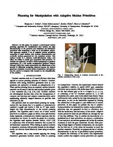
The RAMP Dynamic Obstacles Structural Model describes the data structures used for representing the interactions that possibly occur between mobile obstacles in planar motion and the RAMP robot. The RAMP Dynamic Obstacle Behavioral Models describe these interactions. The structural model is constructed using a UML class diagram shown in Fig. 4.
The obstacle behavioral test model can be defined as a dynamic obstacle process set (DOPS), which is a set of concurrent processes DOP S = {P1 , P2 , . . . , Pi } where 1 ≤ i ≤ M and M is the number of obstacles. Each process Pi is covered by an internal test path T Pi (tpi1 ): pi1 pi2 stopped −−→ moving −−→ stopped. Since the obstacles behave concurrently, the internal test paths are considered concurrent as well. For three obstacles, there are 9 types of concurrency among the three obstacle test paths, which form Abstract Behavioral Test Cases (ABTCs). To transform these ABTCs into executable test cases, we use Each Choice Coverage criterion to select test-data (i.e., test values) that exploit the ABTCs. D. Test Generation
Fig. 4: Dynamic Obstacles Structural Model The TestArea class describes a small operation area to place obstacles so that each obstacle will be close enough to the robot to have a significant impact on the robot’s behavior. The robot’s initial location will be at the lowerleft corner, and the goal location will be at the upperright corner of the test area. In such a small spatial and temporal neighborhood, obstacle motion can be reasonably modeled as having constant linear and angular velocity. Therefore, the DynamicObstacle class consists of current position, velocity values, and the ID of an obstacle. The parameters initial position, linear velocity, angular velocity, stop duration, and move duration are input-domains [6], which are exploited to generate test-data. In this paper, we consider three obstacles with unforeseen motion. The obstacles have two behaviors: move and stop. The behaviors transition the obstacles into one of two states: stopped and moving. These states are translated as test messages and sent to the RAMP system. TABLE VI: Predicates of Dynamic Obstacle EFSMs Dynamic Obstacle i’s Predicate: pi1 = (move()/ − /moving()/moving() : T rajectory) pi2 = (stop()/ − /stopping()/stopped() : P osition)
The RAMP system will receive this information, predict obstacle movement, and then attempt to find a trajectory for the robot to avoid obstacles. Thus, the functionality of RAMP can be evaluated by manipulating the RAMP system with sequences of messages containing obstacle EFSM states and their parameter values. Each obstacle EFSM is associated with a set of predicates, Pi , as illustrated in Table VI. These events are ordered as sequences of method invocations (i.e., function calls) to represent a test path that shows an obstacle’s motion pattern (e.g., {stop() → move(v, ω) → stop()}, where v is linear velocity and ω is angular velocity).
The input-domain of each obstacle for testing RAMP consists of initial position, stop duration, move duration, linear velocity, and angular velocity. The x and y values for initial positions begin at 0.5m so that they are not in a critical range of the robot. The initial position values are blocked (i.e., are divided into different blocks) based on the initial distance from the robot because obstacles that are closer to the robot will affect the population of robot trajectories more than obstacles further away. Parameter value ranges regarding obstacle motion are based on real obstacle robots. The maximum speed of the mobile robot is 0.25m/s. The range of linear velocity for dynamic obstacles is set to be (0, 0.5)m/s so that the obstacle speed can be separated into two equally sized blocks: one block of values that are less than the robot’s maximum speed, and another block of values that are greater than the robot’s maximum speed. The values for angular velocity are blocked in order to separate the direction of obstacle curves. Note that a full tuple representing a test case considers all obstacles and makes sure that each obstacle’s position will be unique for a test case. Based on the maximum speed of each obstacle and the test area size, the ranges for the two duration values, ds and dm , are set to [0, 10] seconds. TABLE VII: Input-Domains and Blocks of Values Parameter
Input-Domains
Blocks of Values
initial position
x = [0.5, 2]m y = [0.5, 2]m
[0.5, 1],(1, 1.5],(1.5, 2] [0.5, 1],(1, 1.5],(1.5, 2]
linear velocity
v = (0, 0.5) m s
[0, 0.25],(0.25, 0.5]
(− π2 , π2 )
[− π2 , 0],(0,
angular velocity
w=
stop duration
ds = [0, 10]s
[0, 10]
move duration
dm = [0, 10]s
[0, 10]
π ] 2
As shown in Table VII, the input-domains consist of 12 total blocks, which lead to a large number of test-data sets. VI. T EST E XECUTION AND E VALUATION The Google Test Library (i.e., gtest) [20] was used for test execution to evaluate component interaction. It provides AS-
SERT * and EXPECT * macros that help verify correctness and performance of multithread programs [21]. TABLE VIII: Executable Test Case Suites Criteria
EP C SP C
EP C SP C
IT Pi
# TCs
Expected Results
Achieved
IT P1 IT P2 IT P3 IT P4 IT P5 IT P6
Purpose: Functional evaluation 8 10 6 Size(trajectory) 6 500 8 0 < f itness 6 2 8 mod path 6= previous path 12 latestM otionState 6= N ull 9 control ← trajectory 15 latestMotionState is changed
Y Y Y Y Y Y
IT P1 IT P2 IT P3 IT P4 IT P5 IT P6
Purpose: Performance assessment 8 5ms 6 duration 8 5ms 6 duration 8 5ms 6 duration 12 5ms 6 duration 9 10ms 6 duration 15 10ms 6 duration
Y Y Y Y Y Y
6 6 6 6 6 6
50ms 50ms 50ms 50ms 100ms 100ms
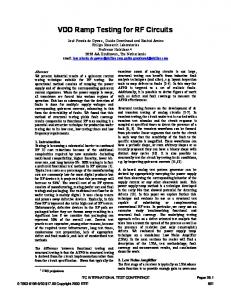
A. RAMP Component Integration Testing and Evaluation As shown in Table VIII, a total of 120 executable test cases were scripted and grouped based on their purpose. The results of test case execution are shown in Table VIII, which indicate that all expected correct results are achieved. Each interaction test path, IT P1 − IT P6 , can be viewed in detail in Table IV. The test cases were executed on a machine running Ubuntu 14.04 with ROS Indigo, using a 32-bit dual-core 1.60GHz Intel pentium IV with 1GB of memory. The time performance results of executing the six internal test paths are shown in Fig. 5a, which indicate that RAMP components run efficiently. Note that IT P5 and IT P6 are much longer test paths than the others and take longer time to run. B. RAMP System-level Testing and Evaluation For each test case, a small test area of 2m × 2m is generated for RAMP. Each test case runs for a maximum of 20 seconds and the results are collected afterwards. The initial position of the robot is the lower left-hand corner of the test arena and the goal position is the upper-right hand corner. As stated before, the size of the test area is small enough to focus on interactions between the robot and obstacles, but also large enough to allow the robot and obstacles space to maneuver. The RAMP system tested is the version described in [8]. At the start of each test case, the obstacle initial positions are chosen randomly from the input domain and made sure that they are at least a minimum distance of 0.2m apart from each other to avoid overlap. The initial orientation of each obstacle is set to be pointing to the robot. The obstacles remain stopped for one second so that RAMP can build a trajectory population based on the static obstacles as planning history. This is necessary because, unlike a purely reactive planner, RAMP is a global and goal-oriented planner that constantly improves and adapts the robot’s motion to changes in the environment as the robot moves from a start location to a goal location. The trajectory population is also seeded with a trajectory in the direction of the robot’s orientation. After that initial delay time has passed, the obstacles will begin to move concurrently according to the ABTC for
testing. The remaining parameter values are chosen randomly from the corresponding input domains for each test case. With a sufficient number of test cases built and tested as described above, the Each Choice Criterion is satisfied. Since an automated test scripting is not available, all ABTCs are scripted manually. 4 out of 9 ABTCs were used for testing and a total of 905 test cases were run.
(a) Performance of RAMP com-(b) RAMP system-level performance over 905 test cases ponents
(c) Histogram of time left on feasible trajectories
Fig. 5: RAMP System Performance Results After each test case, the following results are recorded: Reached goal, a boolean value indicating that the robot has reached its goal within the test period, Feasible trajectory, a boolean value to indicate if the robot is on a feasible trajectory (see Section II-C), Remaining time, the remaining time until the robot reaches the goal if the robot is on a feasible trajectory, Stuck in imminent collision, a boolean value to indicate that the robot stopped indefinitely. Fig. 5b shows that in 8% of the cases, the robot stops indefinitely, which is undesirable. In all other cases, which include 18% of cases when the robot pauses for imminent collision and then moves again, the robot either reaches its goal during the test period of 20 seconds, is on a feasible trajectory to reach its goal in due time, as shown in the histogram of remaining time to goal in Fig. 5c, or is on an infeasible trajectory, trying to get on a feasible one. The main reason that the robot gets stuck at imminent collision is due to an unexpected delay in RAMP to command the robot to stop for imminent collision. This can cause the robot to stop too late and too close to the obstacle so that no trajectory from the robot’s stopped position will be considered safe to move on. VII. C ONCLUSIONS This paper presents the application of an MBT generation technique to testing RAMP component integration performance and system-level performance. Both RAMP components and dynamic obstacles were modelled with interaction test models, and a model-based
Fig. 6: UML Class Diagram that Represents Structural Model for RAMP Components
test generation process was subsequently applied to generate tests for component-integration and system-level testing. The results show that the MBT technique is effective for testing the behavior of RAMP. While the results show that RAMP components interact correctly, it also shed light on how the system-level performance against unforseen obstacles can be improved. Although the paper focuses on RAMP as a use case, the introduced MBT technique is very promising for component interaction testing and system level testing of other real-time motion planning systems. VIII. A PPENDIX A. RAMP Components Structural Model The structural model is constructed using a UML class diagram, where classes are constructed to represent the interprocess messages of RAMP components. The diagram describing every class in the particular RAMP implementation used for testing [8] is shown in Fig. 6. R EFERENCES [1] A. Jacoff, E. Messina, B. Weiss, S. Tadokoro, and Y. Nakagawa, “Test arenas and performance metrics for urban search and rescue robots,” in IEEE Int. Conf. on Intell. Robots and Sys. (IROS), 2003. [2] J. Laval, L. Fabresse, and N. Bouraqadi, “A methodology for testing mobile autonomous robots,” in IEEE/RSJ IROS, Nov 2013. [3] M. Quigley, K. Conley, B. Gerkey, J. Faust, T. Foote, J. Leibs, R. Wheeler, and A. Y. Ng, “ROS: an open-source robot operating system,” in Work. on open source software (ICRA), 2009. [4] C. Pepper, S. Balakirsky, and C. Scrapper, “Robot simulation physics validation,” in Work. on Perf. Metrics for Intel. Sys. ACM, 2007. [5] N. Koenig and A. Howard, “Design and use paradigms for gazebo, an open-source multi-robot simulator,” in IEEE/RSJ IROS, 2004. [6] P. Ammann and J. Offutt, Introduction to Software Testing, 1st ed. 32 Avenue of the Americas, New York, NY 10013, USA: Cambridge University Press, 2008.
[7] J. Vannoy and J. Xiao, “Real-time adaptive motion planning (RAMP) of mobile manipulators in dynamic environments with unforeseen changes,” Robotics, IEEE Trans., 2008. [8] S. McLeod and J. Xiao, “Real-time adaptive non-holonomic motion planning in unforeseen dynamic environments,” in IEEE/RSJ IROS, 2016. [9] A. Andrews, M. Abdelgawad, and A. Gario, “Towards world modelbased test generation in autonomous systems,” in Int. Conf. on ModelDriven Eng. and Soft. Dev. SCITEPRESS Digital Library, 2015. [10] ——, “Active world model for testing autonomous systems using CEFSM,” in Work. on Model-Driven Eng., Ver. and Val., 2015. [11] A. Dias-Neto, R. Subramanyan, M. Vieira, and G. H. Travassos, “A survey on model-based testing approaches: A systematic review,” in ACM Int. Work. on Empirical Assessment of Soft. Eng. Lan. and Tech. [12] R. Lill and F. Saglietti, “Testing the cooperation of autonomous robotic agents,” in Int. Conf. on Soft. Eng. and Apps., Aug 2014. [13] J. Guan and J. Offutt, “A model-based testing technique for component-based real-time embedded systems,” in IEEE Int. Conf. on Soft. Test., Ver., and Val. Work. (ICSTW), 2015. [14] K. T. Cheng and A. Krishnakumar, “Automatic functional test generation using the extended finite state machine model,” in Int. Design Automation Conference. ACM, 1993. [15] D. Brand and P. Zafiropulo, “On communicating finite-state machines,” J. ACM, vol. 30, no. 2, pp. 323–342, Apr. 1983. [16] M. Gouda, E. Manning, and Y. Yu, “On the progress of communication between two finite state machines,” Information and Control, vol. 63, no. 3, pp. 200–216, 1984. [17] R. Yang and C.-G. Chung, “A path analysis approach to concurrent program testing,” in Int. Phoenix Conf. on Comps. and Comms., 1990. [18] R. Lill and F. Saglietti, “Model-based testing of autonomous systems based on coloured petri nets,” in ARCS Workshops (ARCS), 2012. [19] M. Sighireanu, C. Chaudet, H. Garavel, M. Herbert, R. Mateescu, and B. Vivien, “Lotos NT user manual,” 2000. [20] Google. (2013) Google C++ Testing Framework. [Online]. Available: https://code.google.com/p/googletest/ [21] A. Paikan, S. Traversaro, F. Nori, and L. Natale, Model. and Sim. for Auto. Sys.: Int Work., MESAS. Springer International Publishing, 2015, ch. A Generic Testing Framework for Test Driven Development of Robotic Systems.