implementation, it is not always feasible to generate implementation code. As a ..... Timer ref TempFailure = ANY aa WHERE (aa â agents) ⧠(aa â timers).
Model-based Testing Using Scenarios and Event-B Refinements Qaisar A. Malik, Johan Lilius, and Linas Laibinis ˚ Abo Akademi University, Department of Information Technologies Turku Centre for Computer Science (TUCS), Finland {Qaisar.Malik, Johan.Lilius, Linas.Laibinis}@abo.fi
Abstract. In this paper, we present a model-based testing approach based on user provided testing scenarios. In this approach, when software model is refined to add/modify features, the test cases are automatically refined to incorporate these changes. We use the Event-B formalism for software models, while user scenarios are represented as Communicating Sequential Process (CSP) expressions.
1
Introduction
Testing is an important activity in the software development life cycle. With advancements in the model-based approaches for software development, new ways have been explored to generate test-cases from existing models of the system. This is often referred to as model-based testing. A software model is usually a specification of the system which is developed from the given requirements early in the development cycle [5]. For dependable systems, software model should also include fault tolerance mechanism as part of their functionality. In this paper, we present a model-based testing approach based on user-provided testing scenarios. As our formal framework we use the Event-B method [4, 3] supporting stepwise system development by refinement. Generally, implementation code for a system-under-test (SUT) can be generated from a sufficiently detailed specification. But often, due to the remaining abstraction gap between a model and the implementation, it is not always feasible to generate implementation code. As a result, the implementation is not shown to be correct by construction but instead it is hand-coded by programmer(s). Identifying and writing testing scenarios for such an implementation is a very time consuming and error-prone process. In our approach, test scenarios are identified at an abstract specification level and are automatically refined (together with a specification) at each refinement step. These scenarios can also include tests of the incorporated fault tolerance mechanisms. In our approach, test scenarios are represented as Communicating Sequential Process (CSP) [6] expressions. In the final step, executable test cases are generated from these CSP expressions to be tested on SUT. This work is based on our earlier approach [10] for scenario-based testing from B models. The organisation of the paper is as follows. Section 2 discusses stepwise development using the Event-B formalism. Section 3 describes our approach for
model-based testing as well as addresses the topics on refinement and representation of test scenarios. In Section 4, we illustrate our approach by development of a fault-tolerant system. Section 5 contains some concluding remarks.
2
Developing Systems by Refinement using the Event-B Method
This section gives a brief introduction to the Event-B [4, 3] formalism. We also discuss the stepwise development methodology in Event-B focusing on the basic types of system refinement.We will use these basic refinement rules in our modelbased testing approach described in the next section. 2.1
Modeling in Event-B
The Event-B [4, 3] is a recent extension of the classical B method [2] formalism. Event-B is particularly well-suited for modeling event-based systems. The common examples of event-based systems are reactive systems, embedded systems, network protocols, web-applications and graphical user interfaces. In Event-B, the specifications are written in Abstract Machine Notation (AMN). An abstract machine encapsulates state (variables) of the machine and describes operations (events) on the state. A simple abstract machine has following general form MACHINE AM SETS TYPES VARIABLES v INVARIANT I INITIALISATION INIT EVENTS E1 = . . . ... EN = . . . END
A machine is uniquely defined by its name in the MACHINE clause. The VARIABLE clause defines state variables, which are then initialized in the INITIALISATION clause. The variables are strongly typed by constraining predicates of the machine invariant I given in the INVARIANT clause. The invariant defines essential system properties that should be preserved during system execution. The operations of event based systems are atomic and are defined in the EVENT clause. An event is defined in one of two possible ways E = WHEN g THEN S END E = ANY i WHERE C(i) THEN S END
where g is a predicate over the state variables v, and the body S is an Event-B statement specifying how the variables v are affected by execution of the event. The second form, with the ANY construct, represents a parameterized event where i is the parameter and C(i) contains condition(s) over i. The occurrence of the events represents the observable behavior of the system. The event guard (g or C(i)) defines the condition under which event is enabled.
2.2
Refinement of Event-Based Systems
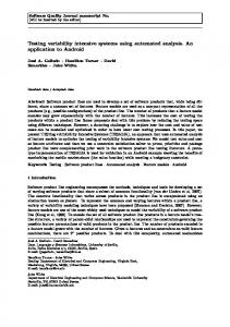
The basic idea underlying the formal stepwise development is to design system implementation gradually, by a number of correctness preserving steps, called refinements. The refinement process starts from creating an abstract, albeit implementable, specification and finishes with generating executable code. In general, refinement process can be seen as a way to reduce non-determinism of the abstract specification, to replace abstract mathematical data structures by data structures implementable on a computer, and, hence, gradually introduce implementation decisions. We are interested how refinement affects the external behavior of a system under construction. Such external behavior can be represented as a trace of observable events, which then can be used to produce test cases. From this point of view, we can distinguish two different types of refinement called atomicity refinement and superposition refinement. In Atomicity refinement, one event operation is replaced by several operations, describing the system reactions in different circumstances the event occurs. Intuitively, it corresponds to a branching in the control flow of the system. Let us consider an abstract machine AM A and a refinement machine AM AR given below. It can be observed that an abstract event E is split (replaced) by the refined events E1 and E2. Any execution of E1 and E2 will correspond to some execution of abstract event E1. It is also shown graphically in Fig.1(a). MACHINE AM A ... EVENTS E = WHEN g THEN S END END
REFINEMENT AM AR REFINES AM A ... EVENTS E1 ref E = WHEN g ∧ g1 THEN S1 END E2 ref E = WHEN g ∧ g2 THEN S2 END END
In Superposition refinement, new implementation details are introduced into the system in the the form of new events that were invisible in the previous specification. These new events can not affect the variables of the abstract specification and only define computations on newly introduced variables. For our purposes, it is convenient to further distinguish two basic kinds of superposition refinement, where – a non-looping event is introduced, – a looping but terminating event is introduced. Let us consider an abstract machine AM S and a refinement machine AM SR as shown below MACHINE AM S ... EVENTS E = WHEN g THEN S END END
REFINEMENT AM SR REFINES AM S ... EVENTS E = WHEN g THEN S END E1 = WHEN g1 THEN S1 END END
It can be observed that the refined specification contains both the old and the
new events, E and E1 respectively. To ensure termination of the new event(s), the VARIANT clause is added in a refinement machine. This VARIANT clause contains an expression over a well-founded type (e.g., natural numbers). The new events should decrease the value of the variant, thus guaranteeing that the new events will eventually return the control as the variant expression can not be decreased indefinitely. These two types of refinements are also shown graphically in Fig.1(b) and (c). Let us note that the presented set of refined types is by no means complete. However, it is sufficient for our approach based on user defined scenarios. E1 E
E2 (a) E
E
E1
(b) E1 E
E
(c)
Fig. 1. Basic refinement transformations
3 3.1
Our Approach for Model-Based Testing Scenario-based approach for testing
In the literature, we can find several definitions of the term scenario. Scenarios are generally used to represent system requirements, analysis, user and component interaction,test cases etc [9]. We use the term scenario to represent a test scenario for our system under test (SUT). A test scenario is one of possible valid execution paths that the system can follow. In other words, it is one of expected functionalities of the system. For example, in a hotel reservation system, booking a room is one functionality, while canceling a pre-booked room is another one. In this article, we use both terms functionality and scenario interchangeably. Each scenario usually includes more than one system-level procedure/event, which are executed in some particular sequence. In a non-trivial system, identifying such a sequence may not be an easy task. Our testing approach is based on stepwise system development, where an abstract model is first constructed and then further refined to include more details (e.g., functionalities) of the system. On the abstract level, an initial scenario is provided by the user. Afterwards, for each refinement step, scenarios are refined automatically. In Fig.2, an abstract model Mi is refined by Mi+1 (denoted by Mi ⊑ Mi+1 ). Scenario Si is an abstract scenario, formally satisfiable (|=) by specification model Mi , provided by
the user. In the next refinement step, scenario Si+1 is constructed automatically from Mi , Mi+1 and Si in such a way that Si+1 formally satisfies model Mi+1 .
M
i
S
i+1
S
i T
M
i+1
T
M
S
i+n
System implementation
i+n
Test implementation Test application
SUT
Test cases
Fig. 2. Overview of our Model-based testing approach
Each scenario can be represented as a Communicating Sequential Process (CSP) [6] expression. Since we develop our system in a controlled way, i.e. using basic refinement transformations described in Section 2.2, we can associate these Event-B refinements with syntactic transformations of the corresponding CSP expressions. Therefore, knowing the way model Mi was refined by Mi+1 , we can automatically refine scenario Si into Si+1 . To check whether a scenario Si is a valid scenario of its model Mi , i.e., model Mi satisfies (|=) scenario Si , we use Pro-B model checker [8]. Pro-B supports execution (animation) of Event-B specifications, guided by CSP expressions. The satisfiability check is performed at each refinement level as shown in the Fig.2. The refinement of scenario Si is the CSP trace-refinement denoted by ⊑T . After the final refinement, the system is implemented from the model Mi+n . This implementation is called system under test (SUT). The scenario Si+n , expressed as a CSP expression, is unfolded into the executable test cases that are then applied to SUT. In the next sections we will demonstrate how scenarios are represented and refined as CSP expressions. 3.2
Scenario Refinement and Representation
As we have described before, the scenarios are represented as CSP expressions. We refine our models in a controlled way targeting at individual events. We assume that the events are only executed when their guards are enabled. For simplicity, we omit the guard information from CSP expressions. Here we will discuss how individual refinement steps effect the scenarios. Let us assume we are given an abstract specification M0 with three events, namely, A, B and C, and a scenario S0 representing the execution order of these events: first the event A, then the event B, and finally the event C. As a regular expression, we can write this sequence as:
A.B.C and its corresponding CSP expression is given by S0 = A → B → C → SKIP In the next refinement step, the model M0 is refined by M1 . This refinement step may involve any of three types of the supported refinements discussed in Section 2.2. We will discuss them one by one. Atomicity Refinement. Let us suppose an event B is refined using atomicity refinement. As a result, it is split into two events namely B1 and B2 . It means that the older event B will be replaced by two new events B1 and B2 modelling a branching in the control flow. This can be shown as the regular expression A.(B1 + B2 ).C As a CSP expression we can represent it as S1 = A → ((B1 → C → SKIP) ⊓ (B2 → C → SKIP)) where ⊓ is an internal choice operator in CSP. Superposition refinement. Let us suppose we use superposition refinement to refine an event C. As a result, a new non-looping event D is introduced in the system. The new scenario can be expressed as a regular expression: A.B.D.C and as a CSP expression: S1 = A → B → D → C → SKIP Finally, let us suppose we again use superposition refinement to refine event C. However, this time a new looping event D is introduced into the system. The new scenario can be represented as a regular expression A.B.D∗ .C and its corresponding CSP expression is given as S1 = A → B → D → C → SKIP where D is defined as D = D ⊓ SKIP In the next section, we outline how scenarios are unfolded into test cases. 3.3
From Scenarios to Test-cases
Unfolding of scenarios into test cases is a process that is very similar to system simulation. During this process, an Event-B model is initialised and executed, which being guided by the provided scenarios. For our approach, we use Pro-B model checker,which has the functionality to animate B specifications guided by the provided CSP expression. After the execution of each event, present in the scenario, information about the changed system state is stored. In other words, the execution trace is represented by a sequence of pairs < e, s >, where e is an event and s is a post-state (the state after execution of event e). From now on we will refer to a single pair < e, s > as an ESPair. For a finite number of events e1 , e2 .....en , present both in the model M and the System Under Test (SUT), a test case t of length n consists of an initial state INIT and a sequence of ESPairs
t = IN IT, {< e1 , s1 >, < e2 , s2 >, ....... < en , sn >} Similarly, a scenario is formally defined as finite set of related test cases, i.e., scenario S = {t1 , t2 , .., tn } As mentioned earlier, ESPair relates an event with its post-state. This information is stored during test-case generation. For SUT these stored post-states become expected outputs of the system and act as a verdict for the testing. After execution of each event, the expected output is compared with the output of the SUT. This comparison is done with the help of probing functions. The probing functions are such functions of SUT that at a given point of their invocation, return state of the SUT. For a test-case to pass the test, each output should match the expected output of the respective event. Otherwise, we conclude that a test case has failed. In the same way, test cases from any refinement step can be used to test implementation as long as both the implementation and the respective test cases share the same events and signatures.
4
Testing Development of a Fault-Tolerant System
In this section, we show how our testing methodology can be used in the development of a fault-tolerant system . We consider an example of a mobile agent system [7], where an agent performs three basic tasks when connected to the server. These basic tasks are named as Engage, NormalActivity and Disengage. To incorporate the fault-tolerant behavior, the system is repeatedly refined using the basic refinement types described in Section 3.2. The introduction of faulttolerance increases the complexity of the system. Our testing methodology can be applied to test the new scenarios that result from this complexity. The initial Event-B machine named Cama specify the three basic events, mentioned above. MACHINE Cama SETS Agents VARIABLES agents INVARIANT agents ⊆ Agents INITIALISATION agents:= ∅ EVENTS Engage = ANY aa WHERE aa ∈ Agents ∧ aa 6∈ agents THEN agents := agents ∪ {aa} END; NormalActivity = ANY aa WHERE aa ∈ Agents ∧ aa ∈ agents THEN skip END ; Disengage = ANY aa WHERE aa ∈ Agents ∧ aa ∈ agents THEN agents := agents - {aa} END END
In the specification Cama, let us note that the event NormalActivity may happen zero or more times. The sequence of events, as determined by the specification, is shown in Fig.3(a). In the next refinement machine Cama1, the event Disengage is refined into
two new events in order to differentiate between leaving normally or because of a failure. This refinement step is atomicity refinement as discussed in Section 3.2. The other events of the specification remain the same. The execution graph for this refinement is shown in Fig.3(b). REFINEMENT Cama1 REFINES Cama ... EVENTS ... NormalLeaving ref Disengage = ANY aa WHERE aa ∈ Agents ∧ aa ∈ agents THEN agents := agents - {aa} END Failure ref Disengage = ANY aa WHERE aa ∈ Agents ∧ aa ∈ agents THEN agents := agents - {aa} END END
NormalActivity
NormalActivity INIT
NormalLeaving Engage
INIT
Final states Failure
Disengage
Engage
(a) Execution graph of Cama
(b) Execution graph of Cama1
NormalActivity INIT
NormalActivity INIT
NormalLeaving
NormalLeaving Engage
Engage
Final states
Final states Failure
Failure TempFailure
Disconnect
TempFailure
(c) Execution graph of Cama2
(d) Execution graph of Cama3
NormalActivity NormalLeaving
INIT Engage
AgentFailure
Timer
Final states
Timer Expiration Connect Disconnect
(e) Execution graph of Cama4 Fig. 3. All possible Event execution scenarios across refinements
In the next refinement machine Cama2, we introduce temporary loss of connection for our agents. This new event is called TempFailure. This refinement step introduces a looping event (see superposition refinement in Section 3.2). To guarantee termination of the new event, we introduce a new variable disconn limit, which is used as a variant.
REFINEMENT Cama2 REFINES Cama1 ... VARIABLES agents, disconn limit INVARIANT disconn limit ∈ NAT VARIANT disconn limit EVENTS ... NormalActivity = ANY aa WHERE aa ∈ agents THEN disconn limit := Disconn limit END; TempFailure = ANY aa WHERE (aa ∈ agents) THEN disconn limit := disconn limit - 1 END; END
The execution flow for Cama2 is given in Fig.3(c). In next refinement machine Cama3, a new event Disconnect is introduced. It is the event that precedes (causes) TempFailure. This refinement is a superposition refinement introducing a non-looping event. A new variable timers is used to ensure order of execution. REFINEMENT Cama3 REFINES Cama2 ... EVENTS ... Disconnect = ANY aa WHERE aa ∈ agents THEN timers := timers ∪ {aa} END TempFailure = ANY aa WHERE (aa ∈ agents) ∧ (aa ∈ timers) THEN disconn limit := disconn limit - 1 || timers := timers - {aa} END; END
The execution flow for Cama3 is shown in Fig.3(d). In the final refinement step, we elaborate on error recovery and time expiration by splitting the events TempFailure and Failure by atomicity refinement. REFINEMENT Cama4 REFINES Cama3 ... EVENTS ... TimerExpiration ref Failure = ANY aa WHERE (aa ∈ agents) ∧ (aa ∈ ex agents) THEN agents := agents - {aa} || ex agents := ex agents - {aa} END; AgentFailure ref Failure = ANY aa WHERE (aa ∈ agents) ∧ (aa 6∈ timers) ∧ (aa 6∈ ex agents) THEN agents := agents - {aa} END; Connect ref TempFailure = ANY aa WHERE (aa ∈ agents) ∧ (aa ∈ timers) THEN disconn limit := disconn limit - 1 || timers := timers - {aa} END; Timer ref TempFailure = ANY aa WHERE (aa ∈ agents) ∧ (aa ∈ timers) THEN disconn limit := disconn limit - 1 || ex agents := ex agents ∪ {aa} ||
timers := timers - {aa} END END
The execution graph for Cama4 is shown in Fig.3(e). This graph shows all the possible events with their respective states but the order of execution is controlled by their guards. In addition, the Fig.4 shows all the possible scenarios based on the information derived from events’ guards and bodies. The dashed NormalActivity
INIT
NormalActivity
INIT
NormalLeaving Engage
Engage AgentFailure
Connect
Disconnect
Connect Disconnect
(a) Event execution possibility 1
(b) Event execution possibility 2
NormalActivity
INIT Engage TimerExpiration
Timer Disconnect
(c) Event execution possibility 3 Fig. 4. All possible Event execution scenarios
arrows represent possible loops of the event(s) during the execution. In order to generate concrete test cases from such models, the number of executions of an event in the loop can be restricted to some finite bound. The value for this bound depends on user’s coverage criteria. The CSP representations of the Cama and Cama4 machines are shown in the following. Cama = Engage_Guard & Engage -> Node2;; Node1 = NormalActivity_Guard & NormalActivity -> Node1;; Node1 = Disengage_Guard & Disengage -> SKIP ;; ⊑ .... ⊑ Cama4 Node1 Node1 Node1 Node1 Node1
= = = = = =
Engage_Guard & Engage -> Node1;; NormalActivity_Guard & NormalActivity -> Node1 ;; Disconnect_Guard & Disconnect -> Node2 ;; Failure_Guard & Failure -> SKIP ;; NormalLeaving_Guard & NormalLeaving -> SKIP ;; TimerExpiration_Guard & TimerExpiration -> SKIP ;;
Node2 = TempFailure_Guard & TempFailure -> Node1 ;; Node2 = Timer_Guard & Timer -> Node1 ;; These CSP expressions can be unfolded into test cases as described in Section 3.3.
5
Conclusions
In this paper, we presented a model-based testing approach based on automatic refinement of test scenarios. This work is being done as a possible extension (plug-in)for the RODIN open-source platform [1]. The EU project RODIN adopts systemic approach for development of complex systems in which faulttolerance mechanisms are incorporated together with main system functionality. The scenario-based testing approach, presented in this paper, has been tried in several RODIN case-studies where fault-tolerance is the major concern. Our approach can also be used in formal software development process in general.
Acknowledgments This work is supported by IST FP6 RODIN Project.
References 1. Rigorous Open Development Environment for Complex Systems. IST FP6 STREP project, online at http://rodin.cs.ncl.ac.uk/. 2. J.-R. Abrial. The B-Book. Cambridge University Press, 1996. 3. J.-R. Abrial. Event Driven Sequential Program Construction. 2000. Available at http://www.matisse.qinetiq.com. 4. J.-R. Abrial and L.Mussat. Introducing Dynamic Constraints in B. Second International B Conference, LNCS 1393, Springer-Verlag, April 1998. 5. Dalal S.R. et al. Model Based Testing in Practice . Proc. of the ICSE’99,Los Angeles,pp 285-294, 1999. 6. C. A. R. Hoare. Communicating sequential processes. Prentice-Hall, Inc., 1985. 7. Linas Laibinis, Elena Troubitsyna, Alexei Iliasov, and Alexander Romanovsky. Rigorous development of fault-tolerant agent systems. In RODIN Book, pages 241–260, 2006. 8. M. Leuschel and M. Butler. Prob: A model checker for b. Proc. of FME 2003, Springer-Verlag LNCS 2805, pages 855-874., 2003. 9. Leila Naslavsky, Thomas A. Alspaugh, Debra J. Richardson, and Hadar Ziv. Using Scenarios to support traceability. Proc of 3rd int. workshop on Traceability in emerging forms of software engineering, 2005. 10. Manoranjan Satpathy, Qaisar A. Malik, and Johan Lilius. Synthesis of scenario based test cases from b models. In FATES/RV, pages 133–147, 2006.