Model Driven Development of User Interface Prototypes: An Integrated Approach Harald Störrle Technical University of Denmark Richard Petersens Plads, 2800 Lyngby, Denmark
[email protected] ABSTRACT Many approaches to interface development apply only to isolated aspects of the development of user interfaces (UIs), e.g., exploration during the early phases, design of visual appearance, or implementation in some technology. In this paper we explore an integrated approach to incorporate the whole UI development life cycle, connect all stakeholders involved, and support a wide range of levels of granularity and abstraction. This is achieved by using Window/EventDiagrams (WEDs), a UI specification notation based on UML 2 state machines. It affords closer collaboration between different user groups like graphic designers and software developers by integrating traditional pen-and-paper based methods with contemporary MDA-based CASE tools. We have implemented our approach in the Advanced Interaction Design Environemnt (AIDE), an application to support WEDs.
Categories and Subject Descriptors D.2.1 [Software Engineering]: Requirements/Specifications; D.2.2 [Software Engineering]: Design Tools and Technolgies; H.5.2 [Information interfaces and Presentation]: User Interfaces (D.2.2, H.1.2, I.3.6)
Keywords UML, WED, State Machines, GUI design
1.
INTRODUCTION
There are many isolated approaches and tools to tackle individual problems in interface design, but no integrated solution for addressing the whole process of interface design. This leads to process discontinuities implying quality issues and rework. In order to improve the overall process of creating user interfaces, the greatest challenge in interface design we face today is about integration of existing approaches along several dimensions: (1) integration of practices from early to late design process phases to ensure a continuous
Permission to make digital or hard copies of all or part of this work for personal or classroom use is granted without fee provided that copies are not made or distributed for profit or commercial advantage and that copies bear this notice and the full citation on the first page. To copy otherwise, to republish, to post on servers or to redistribute to lists, requires prior specific permission and/or a fee. ECSA 2010, August 23-26, 2010, Copenhagen, Denmark. Copyright 2010 ACM 978-1-4503-0179-4/10/08 ...$10.00.
workflow, (2) integration of appearance and behavior specification to ensure a comprehensive design, and (3) “vertical” integration of abstract and detailed views of an interface to ensure both clarity and detailedness of a UI design.
(1) Continuous Workflow. It is a well known fact that graphic designers appreciate sketching tools: their low viscosity makes them ideal for exploring the design space (cf. [2, 20, 27]). However, the exploration has to turn into engineering eventually, and at that point, developers take over from designers, and visionary sketches are being replaced by formal models and code. Often, the overall development process is greatly affected by this discontinuity of people, cultures, and methods. Thus, we need an approach that can bridge this gap, and support a continuous workflow integrating the first sketchy ideas, the subsequent elaborations, and so on right to the application engineering as such.
(2) Comprehensive Design. While it is relatively easy to specify the appearance of an interface by a drawing, specifying its behavior is much more difficult (cf. [19]). In fact, the only way to completely describe arbitrary complex interface behaviors is by programming them. Obviously, integrating drawings and code in a harmonious way is difficult, further disrupting the interface design workflow. Most people are either good at graphic design or at programming, but rarely at both. Storyboards only offer a partial solution, since they are very much restricted as to the degree of behavior they may express (basically only linear sequences, see [17, p. 105]). So, in order to create comprehensive interface designs, we need a way to integrate both aspects of an interface, appearance and behavior.
(3) Scalable Abstraction. Even small UIs may offer a large number of affordances, all of which act together to create the overall user experience. Capturing them in a prototype is expensive, time consuming, and inhibiting change. Capturing them in a more abstract specification will lead to a bloated and/or fragmented design that is difficult to reintegrate, maintain, and communicate. Establishing and maintaining consistency is an arduous and complex task [15]. So, we need a way of managing the complexity of large interface designs in such a way, that neither the clarity of the initial vision, nor the details of the interactions get lost.
APPROACH
3.
WINDOW/EVENT-DIAGRAMS
In this section we describe the Window/Event-Diagrams (WEDs) as a visual language. Syntactically, a WED looks like a complex storyboard using iconic representations many of the common GUI widgets and events. Semantically, there is no difference between UML 2 state machines and WEDs; a WED is a UML 2 state machine. Pragmatically, thus, WEDs may be treated either like storyboards, or like state machines, or like both at the
2
Triggers
This paper presents an approach addressing the three issues sketched above with a model based approach, that allows comprehensive interface design by a continuous workflow with scalable abstractions based on a modeling tool. The key observation motivating our work is this: only few interfaces offer very complex and innovative behavior, that can only ever be captured in a prototype. In contrast, most of the interfaces that are being built in industry are fairly conventional, if only for satisfying what users have come to expect. So, our goal is to support developing such middleof-the-road applications. The approach presented here consists of a notation for UI design (Window/Event-Diagram, WEDs), methods for using the notation, and a tool to support them, including the generation of executable UI prototypes from UI models. WEDs blend conventional storyboards with traditional state-machine based interface design methods, and complement them with extensible libraries of standard behaviors, and JavaScript program code, if unavoidable. WEDs are a mere notational variant of UML 2 state machines, while maintainging all of their semantics, allowing us to access the wealth of methods and concepts of the model-driven software development community. The WED notation ensures that an interface design may deal with appearance, behavior, or both of them, thus satisfying the requirement of comprehensiveness. By integrating storyboards and UML, it provides a common artifact that both designers and software engineers readily understand. So, the approach helps to ensure workflow continuity. Finally, the hierarchical nature of UML state machines and tools and concepts for model modularity can be exploited when building a tool to work with WEDs. The remainder of this paper is organized as follows. In the next section, we introduce the WED notation, the associated methods, and the AIDE tool, respectively. Then, we discuss the how well the approach presented here deals with the three aspects of the integration challenge, and where the limits of our approach are, currently. This paper concludes with a discussion of its contribution. The research reported here has actually been started more than ten years ago (see [23, 24]) but has not been received very well back then. It was clear that any further progress would need a massive implementation effort. Back in 2000, the technology and the available libraries were not up to this task, and also, the author worked (mostly) in industry rather than academia from 2001 to 2008, so there were no students available to do the implementation the hard way, and so it was only in 2008 that this work had been resumed. With several major vendors going in this direction right now (e.g. StateFlow in Adobe’s ExpressionBlend), it seems to have come out just at the right time.
hover
left click
double left click
right click
F5
hit Shift+F5
Effects
2.
switch focus
scroll device down
drag-and-drop with mouse
spawn new dialog
terminate spawned dialogs
open modal dialog
output sound
change cursor
scroll down
Status Bar unsaved data
show message in other location
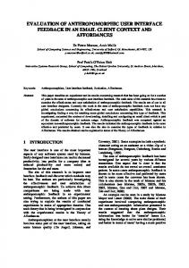
Figure 1: Some of the most common user and system actions (i.e., triggers and effects in UML terminology) used in conventional UI design. same time. So, designers may use WEDs for sketching their UI designs and elaborating their behavior, while developers may elaborate and refine WEDs down to the code level. Additionally, all techniques and tools used in model based software development apply, including comparing, matching, and version control of models, splitting and merging models, consistency checking of models, and so on. Fig. 1 gives an overview over some of the most frequent elements of behavior of WIMP-UIs1 . Of course, the concrete syntax is completely parametric: it may be changed or extended at will. Now consider the WED in Fig. 2. It shows a small portion of an interface design from a teaching example, the Library Management System (LMS). This toy case study is about searching for media in a library, lending them, prolonging, them, and and so on. Fig. 2 shows an interface design for the process of issuing a new reader card. The numbers in red dots are not part of the notation but have been added to improve the presentation here. First, a dialog for entering some data appears. It contains a text field, two groups of radio buttons with two choices each, and two buttons to proceed and abort. The user inputs a reader’s name, selects a few options, and eventually presses “Proceed”. If the data validation is successful, the user must acknowledge the process or abort it. If the process is aborted or the validation was not successful, the user may either revise the inputs or terminate the whole process. Using the window “Issue New Reader Card” right mouse button on the will open a pop-up menu with four options. Now look at the numbers in red dots. States UI widgets liketext boxes or buttons are repre . Groups of widgets and comsented as simple states plete dialogs are modeled as composite states. As a default, only one widget or dialog can be active at any time, which . In order in UML maps to sequential composite states to achieve different behavior, concurrent composite may be 1
Window-Icon-Mouse-Pointer
WED LMS: Issue New Reader Card
Confirm: Issue Card
Issue New Reader Card
Reader 1a First Card
1b
1c
You are about to issue a new reader card for . [input ok]
Proceed
Abort
5a
/ process request
Proceed
[bad input]
Replacement Card Pick up at library Mail to home address
6c
ESC
3b
H*
Auto complete Clear Current Fees Help
Abort
Error: Card Can Not Be Issued 6a 3a
No new reader card will be issued because of .
6b
5b
Proceed
Retry
/ lock window
beep!
Figure 2: A simple WED specifying the user interface for issuing a new reader card. The numbered red dots identify elements of the notation described in the text.
used. Not all states need to be visible in a design. For instance, grouping radio buttons together can be achieved by an invisible compound state. The same applies for layout elements such as vertical boxes. Triggers Positioning a pointer over a WED element is interpreted as putting the focus on that element. Technically, the corresponding state configuration tree is activated. Any user events issued subsequently will be interpreted by that tree, bottom up. For instance, positioning the mouse pointer over the “Abort” button and pushing the left mouse button (a) issues the event S¸ single left clickTˇ in the state “Issue NewReaderCard.Abort” and triggers the transition emanating that state. Likewise, moving the pointer over “Issue New (b) will reset Reader Card” and pressing the Escape key the UI affords the corresponding state. Any (user) actions may be used as triggers. that enforces Guards Transitions may carry a guard the respective condition to be true before the transition is taken. Guards may refer to environment variables that may be used to represent a hidden UI state such as a mode. Effects Then, the effect of the transition (modeling a UI action) is executed and its target state is entered. Effects by plain text (a), code snippets, invo may be described cation of library functions, or maybe visualized by an icon (b). Probably the most common effects are opening a (a), closing one (b), or opening a modal new window (c). dialog Entering States When entering a composite state C (or state machine) for the first time, the substate to be entered is determined by the initial state . Reentering C will reset its state configuration. Reentering a composite state C 0 with a history state , restores the latest state configuration C 0 was in when it was exited. Exit Points (and and Entry Points) help achieving a modular design (this is regular UML 2.2 syntax). Exiting a state (or state machine) automatically exits all sub states, i.e., corresponding windows are closed
by reaching a final node. Secondary Notation Annotations and comment boxes may be used freely; they are represented as UML PseudoStates . As we have said, there is no semantic difference between UML 2 state machines and WEDs. So, every WED construct may be mapped to a UML state machine construct. These mappings are typically very straightforward. Mapping the WED of Fig. 2 into a plain UML state machine yields Fig. 3. SM
LMS: Issue New Reader Card
Confirm: Issue New Card [credentials ok] /spawnWindow()
Issue New Reader Card First Card key(down)
Proceed
key(up)
Replacement Card
Reader Abort
Pick up at library key(down)
key(up)
H*
Mail to home address
Confirm
Abort mouse(l) / switchWindow()
mouse(l) [credentials not ok] /spawnWindow() mouse(l) / spawnWindow()
Error: Card Can Not Be Issued Retry
mouse(l) / closeWindow() mouse(r) / openModalWindow() mouse(l) / closeModalWindow()
key(esc)
mouse(l) / issueRC()
Ok
mouse(l) /beep()
Context Menu Auto complete Clear Current Status Help
Figure 3: This UML state machine is yielded by stripping all appearance cues off the WED seen in Fig. 2 and elaborating effects to procedure calls. Annotations non-behavioral elements like labels may be integrated into the UML meta model as PseudoStates. Variables of the containing UML element may be accessed by GUI elements, such as a variable for the reader’s name in this examples.
4.
WED TECHNIQUES
In this section methodical steps and activities for working with the WED notation are described, grouped by the logical phases of the UI development life cycle. The letters in circles refer to Fig. 4. Creation A , B Early UI designs are mainly concerned with requirements analysis and draw from diverse sources
such as participative workshops with prospective users, analysis of previous or competing products’ UIs, task analysis, and so on. First rough sketches of a storyboard are created, usually with many annotations, to be turned into proper WEDs. AIDE supports this process by importing scans or photos of the dialogs to be annotated manually for behavior, i.e. transitions and events. A group dynamic exercise for participative creation of storyboards with end users has been described in [24]. Elaboration C , D As the next step, the first designs must be elaborated to achieve higher fidelity in appearance and behavior (see C and D ), to expand the scope of the design (e.g., by adding new dialogs), and increase the degree of detail (e.g., by adding new dialogs). Since WEDs may come at any degree of fidelity, both for appearance and behavior, designers are free to elaborate their designs to exactly the degree they feel necessary. Unlike storyboards, this elaboration is not restricted to appearance. Integration E Realistic UI designs are much too large to be dealt with in a single diagram or a monolithic model. There may be independent sub interfaces to be put together, or there may be overlapping parts from several alternative versions that need to be integrated, or there may even be separate models for different aspects to be weaved together. These integration steps would be very challenging without the work done on differencing and merging of models in the last years (cf. the workshops [12, 5]), and the model merge mechanism defined in UML. Validation F At some point, the design must be validated. On the one hand, validation can rely on checking formal consistency conditions or compliance with UI standards. On the other hand, many aspects have to be assessed by user evaluation which requires the user interfaces under test to be executed or simulated. WED supports both of these approaches: there are several tools or checking the consistency of UML state machines based on their formal semantics. Also, AIDE generates XUL code for UI designs which can be executed e.g. in Firefox. Additionally, WEDs may be inspected, as any other types of models. Evolution One of the major advantages of model-based rather than code-based software development is, that it is easier to evolve a system based on an abstract view. For instance, applying consistent changes to key-shortcuts all through an application is an arduous and error-prone task when it is done manually in code. In a UI model such as a WED, individual models may be created for different types of input device (mouse, keyboard, and touchscreen, say). UML’s merge operations between packages is sufficient to incorporate changes to individual models. The fact that WEDs are UML models allows us to carry over many techniques from model driven software development to the domain of UI design. For instance, modularity and version control of models is extremely useful for handling large designs with many levels of abstraction. By helping to maintain overview, they also contribute to preserving manageability and evolvability. UML also offers other mechanisms we have not yet explored, like parameterization of state machines.
5.
THE AIDE TOOL
The Advanced Interaction Design Environment (AIDE) is a highly modular platform independent direct interaction
tool set for creating WEDs, refining and elaborating them in a methodical fashion, supporting distributed concurrent group work, and generating working prototypes from WEDs. AIDE has been under development since 2006, with 15 students at Innsbruck University, Munich University, and the Technical University of Denmark contributing a total of approximately 7,000 work hours to it. Step B in Fig. 4 is actually a screenshot of the AIDE tool. AIDE is created using pure Java, using Piccolo2D, jEdit, JGoodies Looks, the Tango Iconset, VLDocking, and JAXB for persistency. AIDE follows a strict separation of logic and presentation, in order to ensure reusability. So, internally, AIDE separates two views of a WED: the logical representation (maintained by the AIDE core) and the graphical representation (maintained by Piccolo2D). Extensibility of AIDE is ensured by a cartridge mechanism that encapsulates the visual appearance of elements and functions associated with them. Cartridges may be dynamically loaded or unloaded. Apart from the basic cartridges of UML state machines and annotations, there are currently cartridges for the XML User Interface Language (XUL), and for importing hand-drawn storyboards. XUL is used e.g., for defining the UIs of Mozilla projects such as Firefox and Thunderbird. AIDE provides XUL export and integrated simulation. Finally, AIDE also offers unbounded Undo/Redo, user definable roll-back points, tear-off-menus to support very large screens, a locator map, sophisticated zoom and scrolling functions, and multiple views on elements. The first implementation for supporting WEDs delivered a proof-of-concept concerning WEDs and served to explore the (Software) design space. The code base of this initial prototype was completely discarded. The second implementation served to explore some of the Java libraries mentioned above, and established a software architecture fit for a prolonged development. The third iteration improved the code base, and enhanced the functionality so that actual case studies can now be run. The fourth iteration, which has started in February 2010, focuses on enhancing the usability and providing more elaborated cartridges in order to allow AIDE being used in the classroom with larger sets of users. The fifth iteration, which will start in late 2010 will focus on supporting teamwork and group processes.
6.
EVALUATION
While AIDE has now proceeded well beyond the stage of an academic prototype, it is still far from the quality and productivity that would allow us to use it in vivo. So, we can not yet provide results from field studies that would allow to judge our whole approach as compared to the state of the practice. However, we have used WEDs as a method for exploring and creating user interfaces, both in the classroom and in industry (cf. [24]) with positive feedback. In one experiment several groups of students were randomly assigned two tasks of creating the same interface designs using pen and paper, PowerPoint, and the blackboard, respectively. After the exercise, the participants were asked to comment on their respective tools, and the methods. It turned out that those participants that had been using pen and paper came up with the most comprehensive interface model, had by far the most fun doing it, and felt the least restricted by their tool. However, all participants judged
A Sketch & Explore
create initial design as a pen-and-paper storyboard explore design space by e.g. group dynamic exercise elicit interface requirements by e.g. task analysis or reverse engineering
B Digitize & Import
digitize paper dialog sketches by scanner or camera batch import digitized dialogs automatically annotate transitions with triggers,
guards, and effects manually
WED LMS: Issue New Reader Card
C
Confirm: Issue Card
Issue New Reader Card
You are about to issue a new reader card for .
Reader
Proceed
First Card
[input ok]
Abort
Proceed
Elaborate Appearance / process request
[bad input]
Replacement Card Pick up at library Mail to home address
H*
ESC
Auto complete Clear Current Fees Help
/ lock window
Abort
transform sketch into appealing graphics incorporate appearance guidelines layout of WED
Error: Card Can Not Be Issued
D
No new reader card will be issued because of .
Elaborate Behavior
Retry
Proceed beep!
add layers of transitions for event types add guards and effects (e.g. JavaScript) add menues and annotations
E Integrate Parts & Alternatives
combine several WEDs into one using
model merge techniques
F Generate & Validate
generate XUL code for prototype usability test on prototype formal consistency checking expert walkthrough of UI design
Figure 4: Stages in the UI development life cycle using WEDs and AIDE: Starting from a traditional penand-paper wallpaper prototype, subsequent steps of elaboration yield a prototype with executable XUL code. the results created with PowerPoint as being much more appealing and convincing visually. The main advantage (in the eyes of the participants) of using PowerPoint, however, was the ability to demonstrate the result as a slide show, which the other groups couldn’t. The main drawbacks of using PowerPoint were the effort necessary, the lack of flexibility, and the awkwardness of doing teamwork with a tool. With the Storyboaring import facility, AIDE can combine the strengths of early sketching with pen and paper on the one hand, and the added value from an interactive prototype, on the other. In another experience in an industrial project, the WED notation and methods were readily picked up by designers as well as developers. So, graphic designers would keep creating individual screens by their preferred GUI builders, but then print their designs, integrate them into WEDs, and put it all on large wallpapers for presentations.
Clearly, AIDE cannot match the versatility and usability of pen and paper as far as modeling visual appearance is concerned, at least in the current version of AIDE. However, experience also shows that WEDs are a great tool for creating overview and visualizing UI behaviors, and generating working and user-testable prototypes from interface designs gives AIDE a considerable edge over GUI-builders.
7.
RELATED WORK
The usage of flat state machines for the design of UIs goes back to the era of text-only terminals. There, visual appearance played no role, but the integration of UI design into the overall software engineering process, did. See [25, 9, 6, 26, 16, 4, 18, 10, 11]. With the advent of the commercial internet in the late 1990’s, a second group of approaches pursued a dual path: now the main goal was to supporting creativity, flow of de-
sign work, and evaluating the user experience. As a consequence, the visual appearance attracted most of the attention, reducing behavior to the sequential flow of storyboards— quite sufficient for the web pages of the time. Examples are SILK [13], Electronic Cocktail Napkin [7], DENIM [21], SketchWizard [3], DEMAIS [1] and others. Todays authoring tools like Dreamweaver, GoLive, and Expression Blend allow designers to explore the design space at reasonable initial cost, but at the price of lock-in to their respective proprietary technology and platform. Also, such prototypes can be manipulated only at the surface or at the code level. For instance, Expression Blend is locked to Silverlight/WPF and MS Windows/XAML code. Interestingly, Expression Blend has recently been enriched by SketchFlow, which pursues a similar approach as WEDs. The same is true for GUI Builders (e.g., Matisse, Glade), UI prototyping tools (e.g., ForeUI, Virtual Windows [14]) and drawing tools (e.g., Visio, PowerPoint): they all focus on appearance and have little or nothing to offer for interface behavior, apart from raw code. Our approach, on the other hand, combines both appearance and behavior, over a wide range of fidelity, and covers overview models as well as detailed views. A first version of WEDs has been published as a side issue in the author’s Phd-thesis, see [23] in 2001. A process of using WEDs in a group dynamic setting has been published shortly afterwards, see [24]. Developing three prototype tools for WEDs since 2008, the notation and its semantics have been reshaped gradually, so that now there is a substantial difference to the original approach, and a whole new level of detail and confidence in this approach.
8.
CONCLUSION
8.1
Contributions
In Section 1, we have argued that interface design is faced with three integration requirements: allowing/ensuring a continuous development workflow, encompassing all aspects of an interface in a comprehensive design (most notably, appearance and behavior), and providing an approach covering a wide range of levels of granularity, fidelity, and abstraction. We now examine how our approach works towards these requirements.
(1) Continuous Workflow. WEDs support workflow continuity by tying together storyboards and state machines: syntactically, WEDs are storyboards, so graphic and screen designers can easily abstract from the behaviors and focus on the UI appearance. Semantically WEDs are UML state machines, so software developers can easily abstract from the appearance and refer to the underlying model in their work. Since state machines are executable, interactive prototypes may easily be generated for users (and designers) to explore an interface. As it is today, AIDE/WEDs support the stepwise refinement of UI designs, from paper storyboards, importing them via scans/photos, annotating and elaborating them in AIDE to “proper” UML state machines, adding JavaScript for behavioral aspects, and exporting the design as executable XUL code. So, the complete whole workflow from first sketches to executable prototypes is covered. Automatic consistency checking and tool-supported refinement could exploit the wealth of theoretical work done on state machine semantics. The approach
is limited in that only fairly standard UIs can be described using WEDs: innovative ways of interacting are not covered. The approach can be extended of course, and we are currently working on touch screen based interactions, but this has not been realized yet.
(2) Comprehensive Design. Obviously, WEDs allow the user to specify both the appearance and the behavior of a UI, so it is comprehensive in that sense. While it may incorporate behavioral specifications to a much greater degree than storyboards, only predefined behaviors may be used, and not all events and behaviors are easily represented visually. Also, pushing the behavioral fidelity of a model clutters the UI model with detail and so overview is lost. Using a lot of screen real estate helps a little, but still, dealing effectively with abstraction is paramount.
(3) Scalable Abstraction. The AIDE provides many of the usual means to handle abstraction, such as sophisticated zoom control with locator map and reverse scrolling, large screen capabilities like freely arrangeable tear-off menus and extensive context-sensitive pop-up menus. However, tools could also exploit the hierarchical structure of state machines (and WEDs), by providing collapse/expand/refine operations of composite states, model modularization by the UML merge operator or model versioning techniques.
8.2
Shortcomings
First of all, the widget set currently provided with AIDE is insufficient, and the overall usability needs improvement. Also, the state machine semantics has not yet been exploited for automated consistency checks. Finally, we are experimenting with additional means to handle abstraction, e.g., layers and groups of elements, and property sharing through live-copies.
9.
DISCUSSION
This research is motivated by practical UI development experience, and an independent contextual inquiry (cf. [19]). It follows a design science approach [8]. In the first iteration, WEDs and associated techniques have been designed and evaluated in the classroom and in a few small industrial development projects. In the second iteration, we have created a tool prototype to explore implementation options, abandoning the prototype subsequently. In the third iteration, the AIDE tool has been created, and is now being streamlined for industrial usage. In parallel, extensions to cover non-WIMP interfaces based on touchscreens are being investigated. Window/Event-Diagrams (WEDs) are UML 2 state machines enriched by visual stereotypes for the usual elements of conventional WIMP-UIs. Therefore, WEDs look like Storyboards to graphic designers, and like UML state machines to developers, tapping into the intuition and background knowledge of both designers and developers at the same time. This ought to facilitate the communication and exchange of artifacts between these two groups. Most existing tools are good for prototyping UI appearance but offer little help in terms of interface behavior: Either the designers have to resort to plain coding, or they have
to contend with sequences and hyperlinks between individual screens. Our approach, on the other hand, combines both appearance and behavior, over a wide range of fidelity. It is somewhat restricted in that it offers only libraries of predefined behaviors. So, applications with a lot of innovation in user interaction are not easily modeled using the approach presented here; however, many conventional applications or rich internet applications are covered. Our approach is not technology specific, and focuses on the flow of control across several screens rather than individual screens. Storyboarding is great during the early, creative exploration of the design space, but the second step of transforming it into a working prototype that may be evaluated is not so easy. For the more engineering-minded approaches like Wassermann, Denert, and others, it is just the other way round. The WED notation, together with the techniques based on it and the AIDE tool supporting them, supports both of these steps, providing seamless refinement from top to bottom. Accurate models of UIs may be of considerable size since already rather small UIs may afford quite rich interaction. So, the overview and abstraction expected from UI models is at risk. Using WEDs, UI developers have three ways of establishing abstractions. Firstly, there is a rich theory of state machine refinement based on the hierarchic structure inherent to UML state machines. This may be applied to WEDs without alterations, i. e., there is already a theory of WED refinement. Secondly, the UML supports a model merge mechanism (cf. [22, pp. 115]) that can be used to weave together separate models of different aspects. So, different parts of an UI may be specified in isolation but may be joined automatically for simulation, validation, or code generation. Thirdly, a tool supporting WEDs may exploit the hierarchical nature of WEDs in providing the usual tool mechanisms for zooming, splitting up models into layers, aspects, or groups of elements, or selectively displaying only parts or aspects of a model (e. g., suppressing some or all transitions). So, a UI designer may create individual views to support communication and understanding.
10.
ONGOING AND FUTURE WORK
This research is an ongoing project involving several undergraduate and graduate students. The currently ongoing work include: • two Bachelor theses on architectural improvements (to be finished in June 2010); • a MSc thesis on usability improvements validated by a SUMI analysis, also providing a gesture input cartridge (to be finished in July 2010); • a MSc thesis on introducing features for collaborative work and UI ideation, in particular, long transactions, version control with concurrent and alternative versions (to start in July 2010). The usability improvements will allow to use AIDE with real users in the classroom, which will contribute to the experimental verification. This will allow us to conduct a full scale end user evaluation after that. Open problems are the improvement of the rendering and code export (possibly extending code export to include XAML as well as XUL), automatic layout based on teh yFiles library, and dealing with very large WEDs by using several abstraction mechanisms.
Acknowledgements I would like to thank all my students in Innsbruck, Munich, and Lyngby who contributed to the development of the AIDE tool, and who participated in the evaluation experiments. I would also like to thank the anonymous referees for their friendly comments.
11.
REFERENCES
[1] Brian P. Bailey, Joseph A. Konstan, and John V. Carlis. DEMAIS: designing multimedia applications with interactive storyboards. In Proc. 9th ACM Intl. Conf. Multimedia (MULTIMEDIA’01), pages 241–250, New York, NY, USA, 2001. ACM. [2] Bill Buxton. Sketching User Experiences: Getting the Design Right and the Right Design. Morgan Kaufmann, 2007. [3] Richard C. Davis, T. Scott Saponas, Michael Shilman, and James A. Landay. SketchWizard: Wizard of Oz prototyping of pen-based user interfaces. In Proc. 20th Ann. ACM Symp. User Interface Software and Technology (UIST’07), pages 119–128. ACM, 2007. [4] Ernst Denert. Software-Engineering. Springer Verlag, 1. korrigierter Nachdruck edition, 1992. [5] J¨ urgen Ebert, Udo Kelter, and Tarja Syst¨ a, editors. Proc. 2008 Intl. Ws. Comparison and Versioning of Software Models. ACM, 2008. [6] Bruce P. Fraser and David A. Lamb. An Annotated Bibliography on User Interface Design. SIGCHI Bulletin, 21(1):17–28, July 1989. [7] Mark D. Gross and Ellen Yi Luen Do. Demonstrating the electronic cocktail napkin: a paper-like interface for early design. In CHI ’96: Conference companion on Human factors in computing systems, pages 5–6, New York, NY, USA, 1996. ACM. [8] A. Hevner, S. March, J. Park, and S. Ram. Design Science in Information Systems Research. MIS Quarterly, 28(1):75–105, 2004. [9] Robert J.K. Jacob. A Specification Language for Direc Manipulation User Interfaces. ACM Trans. on Graphics, 5(4):283–317, 1986. [10] Robert J.K. Jacob. A Visual Language for Non-WIMP Uer Interfaces. In Proc. IEEE Symp. on Visual Languages, pages 231–238. IEEE, IEEE Press, 1996. [11] Robert J.K. Jacob, Leonidas Deligiannidis, and Stephen Morrison. A Software Model and Specification Language for Non-WIMP User Interfaces. ACM Trans. on Computer-Human Interaction, 6(1):1–46, March 1999. [12] Udo Kelter, editor. Proc. Ws. Versionierung und Vergleich von UML Modellen (VVUU’07). Gesellschaft f¨ ur Informatik, May 2007. appeared in Softwaretechnik-Trends 2(27)2007. [13] James A. Landay and Brad A. Myers. Sketching Interfaces: Toward More Human Interface Design. IEEE Computer, 34(3), March 2001. [14] Soren Lauesen. User Interface Design: A Software Engineering Perspective. Addison-Wesley, 2004. [15] Francisco J. Lucas, Fernando Molina, and Ambrosio Toval. A systematic review of UML model consistency management. Inf. Softw. Technol., 51(12):1631–1645, December 2009.
[16] James A. Martin, Kathleen Kavanagh Chapman, and Joe Leben. System Application Architecture: Common User Access. Prentice Hall, 1991. [17] Scott McCloud. Understanding Comics: The Invisible Art. HarperPerennial, 1993. [18] Brad A. Myers. Report on the CHI’91 Workshop on Languages for Developing User Interfaces. SIGCHI Bulletin, 25(2):20–23, April 1993. [19] Brad A. Myers, Sun Young Park, Yoko Nakano, Greg Mueller, and Andrew J. Ko. How Designers Design and Program Interactive Behaviors. In Paolo Bottoni, Mary Beth Rosson, and Mark Minas, editors, Proc. IEEE Symp. Visual Languages and humand Centric Computing (VL/HCC’08), pages 177–184. IEEE Press, 2008. [20] Mark W. Newman and James A. Landay. Sitemaps, Storyboards, and Specifications: a Sketch of Web Site Design Practice. In Proc. 3rd Conf. Designing Interactive Systems: Processes, Practices, Methods, and Techniques (DIS’00), pages 263–274. ACM, 2000. [21] M.W. Newman and J.A. Landay. Sitemaps, Storyboards, and Specifications: A Sketch of Web Site Design Practice. In Designing Interactive Systems (DIS’00), pages 263–274, 2000. [22] OMG. OMG Unified Modeling Language (OMG UML), Superstructure, V2.2 beta (ptc/08-05-04). Technical report, Object Management Group, May 2008. [23] Harald St¨ orrle. Models of Software Architecture. Design and Analysis with UML and Petri-nets. PhD thesis, LMU M¨ unchen, Institut f¨ ur Informatik, December 2000. ISBN 3-8311-1330-0. [24] Harald St¨ orrle. Group Exercises for the Design and Validation of Graphical User Interfaces. In Martin Glinz and G¨ unther M¨ uller-Luschnat, editors, Proc. Modellierung 2002, number P-12 in Lecture Notes in Informatics, pages 135–146. Gesellschaft f¨ ur Informatik, 2002. [25] Anthony I. Wasserman. Extending State Transition Diagrams for the Specification of Human-Computer Interaction. IEEE Transactions on Software Engineering, 11(8):699–713, August 1985. [26] Pierre D. Wellner. Statemaster: A UIMS based on Statecharts for Prototyping and Target Implementation. In Ken Bice and Clayton Lewis, editors, Proc. Intl. Conf. Computer-Human Interaction (CHI’89), pages 177–182. ACM Press, 1989. [27] Y.Y. Wong. Rough and Ready Prototypes: Lessons from Graphic Design. In SIG Computer Human Interaction (SIGCHI’92), page 685, 1992.