Model-Driven Engineering of User Interfaces: Promises, Successes, Failures, and Challenges Jean Vanderdonckt Belgian Laboratory of Computer-Human Interaction (BCHI), Louvain School of Management (IAG), Université catholique de Louvain, Place des Doyens, 1 – B-1348 Louvain-la-Neuve (Belgium) Phone: +32 10/478525 – Fax: +32 10/478324 – Skype: jeanvdd1712
[email protected], http://www.isys.ucl.ac.be/bchi/members/jva http://www.usixml.org, http://www.similar.cc, http://www.openinterface.org ABSTRACT Model-driven engineering (MDE) of user interfaces consists in describing a user interface and aspects involved in it (e.g., task, domain, context of use) in models from which a final interface is produced. With one big win in mind: when the user’s requirements or the context of use change, the models change accordingly and so does the supporting user interface. Models and a method for developing user interfaces based on MDE are presented in this tutorial supporting forward engineering (a new interface is produced), reverse engineering (an existing interface is improved), and lateral engineering (an existing interface is adapted to a new context of use). Software supporting this method will be used based on UsiXML (User Interface eXtensible Markup Language), a XML-compliant user interface description language.
Categories and Subject Descriptors
derived. Today, no consensus has been reached and no method has really emerged from these initiatives, namely by lack of standardization, but also because the aims and goals may largely vary from one interactive application to another. In this paper, we would like to review the main principles that underpin model-driven engineering of user interfaces in order to make the promises of this methodology more explicit. Then, we would like to examine more closely the three dimensions of such a methodology (i.e., the models, the method, and the tools) in order to discuss some successes and failures of this kind of methodology. Finally, we would like to conclude by identifying a series of challenges that should be solved for the future for unlocking the breaks that remain unsolved. Since 1997, the Object Management Group (OMG – www.omg.org) [28] has launched an initiative called Model-Driven Engineering (MDE) to support the development of complex, large, interactive software systems providing a standardized architecture with which:
D.2.2 [Software Engineering]: Design Tools and Techniques – Computer-aided software engineering (CASE), Evolutionary prototyping, Structured Programming, User Interfaces. H.5.2 [Information Interfaces and Presentation (e.g., HCI)]: User interfaces – Graphical user interfaces, Interaction styles, Input devices and strategies, Prototyping, Voice I/O.
–
General Terms
In MDA, a systematic method is recommended to drive the development life cycle to guarantee some form of quality of the resulting software system. Four principles underlie the OMG’s [28] view of MDA [3,17,20,25]:
Design, Experimentation, Human Factors, Standardization, Languages.
Keywords Domain model, model-driven architecture, model-driven engineering, model-to-model transformation, model-to-code transformation, software quality, task model, user interface description language, user interface model.
1. INTRODUCTION In the past, many attempts to establish a comprehensive modeldriven approach for developing the User Interface (UI) of an interactive application have been launched: from information related task (what are the actions carried out by the user), domain (what are the objects manipulated in this task), user (who is the user), platform (what is the computing platform), environment (in which environment is the user working), the presentation, the dialog, the help, the tutorial of one or many UIs should be Permission to make digital or hard copies of all or part of this work for personal or classroom use is granted without fee provided that copies are not made or distributed for profit or commercial advantage and that copies bear this notice and the full citation on the first page. To copy otherwise, or republish, to post on servers or to redistribute to lists, requires prior specific permission and/or a fee. ROCHI’08, September 18–19, 2008, Iasi, Romania. Copyright © 2008 Jean Vanderdonckt.
– – –
Systems can easily evolve to address constantly evolving user requirements. Old, current and new technologies can be harmonized. Business logic can be maintained constant or evolving independently of the technological changes. Legacy systems can be unified with new systems.
1. Models are expressed in a well-formed unified notation and form the cornerstone to understanding software systems for enterprise scale information systems. The semantics of the models are based on meta-models. 2. The building of software systems can be organized around a set of models by applying a series of transformations between models, organized into an architectural framework of layers and transformations: model-to-model transformations support any change between models while modelto-code transformation are typically associated with code production, automated or not. 3. A formal underpinning for describing models in a set of meta-models facilitates meaningful integration and transformation among models, and is the basis for automation through software. 4. Acceptance and adoption of this model-driven approach requires industry standards to provide openness to consumers, and foster competition among vendors In this approach, models are applied in all steps of development up to a target platform, providing source code, deployment and configuration files,… MDE has been applied to many kinds of business problems and integrated with a wide array of other common computing technologies, including the UI area.
Not all model-driven UI development environments or development methods can pretend to be compliant with these principles. If we apply OMG’s principles to the UI development life cycle, it means that models should be obtained during steps of development until providing source code, deployment and configuration files. MDA has been applied to many kinds of business problems and integrated with a wide array of other common computing technologies. The following definition was approved unanimously by 17 participants of the ORMSC plenary session meeting in Montreal on 23-26 August 2004. The stated purpose of these two paragraphs was to provide principles to be followed in the revision of the MDA guide. MDA is an OMG initiative that proposes to define a set of non-proprietary standards that will specify interoperable technologies with which to realize model-driven development with automated transformations. Not all of these technologies will directly concern the transformation involved in MDA. MDA does not necessarily rely on the UML, but, as a specialized kind of MDD (Model Driven Development), MDA necessarily involves the use of model(s) in development, which entails that at least one modeling language must be used. Any modeling language used in MDA must be described in terms of the MOF language to enable the metadata to be understood in a standard manner, which is a precondition for any activity to perform automated transformation. This definition emphasizes that models are not enough in order to have a fully-MDA compliant UI development environment. Some environments may includes models, but do not rely on a transformational approach as there in no transformation engine based on explicit transformations rules that can be edited by the designer. Or because there is no genuine modelling language behind. It is not just because there is a XML language that a genuine modelling language may exist. This demonstrates that in order to have a full MDA development methodology (and not just a tool), three dimensions should be covered [2]: 1. A genuine UI model or set of related models that are strongly defined based on a trilogy (semantics, syntax, stylistics) as any language should be defined [35]. Offering a XML language does not necessarily include this trilogy. Therefore, a UI model should be supported by a User Interface
Description Language (UIDL) or modelling language that cover this trilogy. 2. A development method that is explicitly based on the previously introduced models and that provides explicit methodological guidance and support to designers and to all people who are involved in the Software Development Life Cycle (SDLC). 3. A tool (or a suite of software tools) that support the enactment of the development method. It is not because a tool is available that a development method has been rigorously defined. Of course, a tool may induce some method, but this process remains poorly defined in a way that is implicit to the tool. A tool should be explicitly developed in order to support a development method, and not just what we have in mind. These three dimensions of a genuine development methodology (or approach) will be addressed in the next sections. First, a general outline and framework will be given, then a particular section will be devoted to each dimension: models, method, and supporting tool.
2. TOWARDS A MDE-COMPLIANT APPROACH FOR USER INTERFACE DEVELOPMENT Our main goal is to examine the experience gained by existing model-driven approaches for developing UIs and to introduce the audience to the development of UIs based on MDE based on this experience. The particular objective is to teach how to practically setup, deploy, and apply a MDE-compliant approach. The one that is outlined here is based on UsiXML (User Interface eXtensible Markup Language – http://www.usixml. org) as a UIDL, but the observations are independent of this language and could be equally applied to other UIDLs such as UIML [15], XIML (www.ximl.org). In [35], we explain that one single UIDL does not fit all and that it is impossible to find out in one UIDL all the qualities required to successfully run a MDE-compliant approach. This UI description language is uniformly used throughout the different steps of a MDE-compliant development life cycle to store the models involved in the various processes.
UsiXML Method engineering TransformiXML IdealXML
FlashiXML, QtkXML GrafiXML, InterpiXML Rendering
UsiXML models: task, domain
Graph transformations
UsiXML model: UsiXML model: Graph Concrete user Abstract user transformations interface interface
Generative programming
Final user interface
VisualiXML Derivation rules
KnowiXML Computing-Independent Model (CIM)
Platform-Independent Model (PIM)
GrafiXML, VisiXML SketchiXML, FormiXML ReversiXML PlastiXML, ComposiXML Platform-Specific Model (PSM)
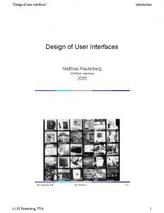
Figure 1. The MDE-compliant approach for UI development based on UsiXML.
Code
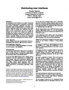
Figure 1 outlines the MDE-compliant approach for developing UIs decomposed into four major steps that result from the Cameleon Reference Framework [4,40]: 1. Task and domain modelling (corresponding to the Computting-Independent Model –CIM– in MDE): where a model is provided for the end user’s task, the domain of activity and, if needed, the context of use (user, platform, and environment). This step is supported by IdealXML [34]. Fig. 2a graphically depicts a task model expressed according to CTT notation [31]. This task model has been extended with new task types, attributes, and relationships. 2. Abstract User Interface (corresponding to the PlatformIndependent Model –PIM– in MDE): this level describes potential user interfaces independently of any interaction modality and any implementation technology. It defines abstract containers and individual components, two forms of Abstract Interaction Objects by grouping subtasks according to various criteria, a navigation scheme between the container and selects abstract individual component for each concept so that they are independent of any modality. An AUI abstracts a CUI into a UI definition that is independent of any modality of interaction (e.g., graphical interaction, vocal interaction, speech synthesis and recognition, video-based interaction, virtual, augmented or mixed reality). An AUI can also be considered as a canonical expression of the rendering of the domain concepts and tasks in a way that is independent from any modality of interaction. An AUI is considered as an abstraction of a CUI with respect to interaction modality. At this level, the UI mainly consists of input/output definitions, along with actions that need to be performed on this information. This step is also supported by IdealXML [34]. Fig. 2b graphically reproduces a AUI. 3. Concrete User Interface (corresponding to the PlatformSpecific Model –PSM– in MDE): this level describes a potential user interface after a particular interaction modality has been selected (e.g., graphical, vocal, multimodal). This step is supported by several tools helping designers and developers to edit, build, or sketch a user interface. For instance, SketchiXML [6,7] (figure 3), GrafiXML [24], FormiXML, ComposiXML [18], PlastiXML [5] and VisiXML for graphical user interfaces. It concretizes an abstract UI for a given context of use into Concrete Interaction Objects (CIOs) so as to define widgets layout and interface navigation. It abstracts a final UI into a UI definition that is independent of any computing platform. Although a CUI makes explicit the final Look & Feel of a final UI, it is still a mock-up that runs only within a particular environment. A CUI can also be considered as a reification of an AUI at the upper level and an abstraction of the final UI with respect to the platform. Fig. 2c reproduces a CUI for a graphical target environment. Each tool pursues a particular goal. Some of them will be exemplified into more details later on in this paper. 4. Final User Interface (corresponding to the code level in MDE): this level is reached when the code of a user interface is produced from the previous levels. This code could be either interpreted or compiled. We hereby define a rendering engine as a software component (or set of components) that are able to interpret a UsiXML file expressed at the CUI level and to run it or a code compiler that (semiautomatically generate code from a UsiXML file expressed at the CUI level. Another level could be imagined as well, but does not present any particular interest. Fig. 2d determines a final UI corresponding to the CUI given in Fig. 2c.
Task & domain
AUI level
CUI level
FUI level
Figure 2. The four levels: (a) task and domain, (b) abstract UI, (c) concrete UI, and (d) final UI.
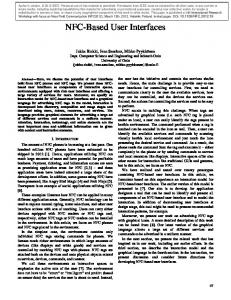
Figure 3. SketchiXML, a tool for sketching a user interface.
3. MODELS Before examining closely what are the challenges regarding the ‘models’ dimension, let us detail more the models of concern in UsiXML. UsiXML is a collection of models for specifying a UI, some of them being used to support a particular level, some other being used to support a transition from one level to another:
Task model: is a model describing the interactive task as viewed by the end user interacting with the system. Domain model: is a description of the classes of objects manipulated by a user while interacting with a system. Mapping model: is a model containing a series of related mappings between models or elements of models. Transformation model: Graph Transformation (GT) techniques based on AGG [9] were chosen to formalize explicit transformations between any pair of models, except from the FUI level. Context model: is a model describing the three aspects of a context of use in which a end user is carrying out an interactive task with a specific computing platform in a given surrounding environment. Consequently, a context model consists of a user model, a platform model, and an environment model. Each of these three facets is itself a model. auiModel: is the model describing the UI at the abstract level as previously defined. cuiModel: is the model describing the UI at the concrete level as previously defined. Process model: is a model organizing tasks in time and space in order to form high-level business processes. Workflow model: is a model structuring business processes into a workflow information system. Resource model: is a model specifying resources that can be consumed by tasks specified in task models.
In UsiXML, the uiModel is the topmost super class containing common features shared by all component models of a UI that may contain any combination of the aforementioned models. This raises the following intertwined challenges that are related to models only. It does not depend from any method relying on these models. But a difficulty already raised at this level may be exacerbated at the next level. Property Completeness Stylistic completeness Consistency Correction Expressiveness Concision Separability Correlability Integrability Meyer’s specification sin [23] Noise Silence Contradiction Surspecification Ambiguity Redundancy Incoherence
C1. Need to ensure quality properties of a model Each used model should in principle benefit from a certain amount of quality properties. Table 1 summarizes some of these properties and Meyer’s seven sins of specification reformulated in order to address modeling quality. For instance, a model should be at least complete, consistent, and correct. This is a heavy assumption that is rarely met. A model is rarely complete because it suffers from an intrinsic incompleteness. But once it is written, it could be consistent and correct. Model checking techniques can automate this process. C2. Need to cover semantics, syntax, and stylistics Continuing with the language definition one can say that syntax deals solely with the form and structure of symbols in a language without any consideration given to their meaning. The abstract syntax is defined as the hidden structure of a language, its mathematical background. FlowiXML [14] uses directed graph as abstract syntax. A concrete syntax is an external appearance; the visual syntax consists of boxes and arrows, a somewhat classic representation for a graphical structure. This visual syntax will be mainly used to in this work as an expression means for the transformation rules that are going to be developed in a future. The textual syntax is described using an XML-based language. The objective of stylistics is to provide a representation of a set of defined objects in order to facilitate their understanding and manipulation in tools. The representation can be of different types (e.g., graphical, textual). If one of the three aspects of the trilogy (semantics, syntax, stylistics) is not rigorously defined, one may fail to ensure the quality properties defined in Table 1. For instance, a UIDL suffering from no semantics may suffer from incorrection, lack of expressiveness, and lack of separability. A UIDL suffering from no stylistics may suffer from stylistic incompleteness and, therefore, from lack of expressiveness.
Definition Ability of a model to abstract all real world aspects of interest via appropriate concepts and relations Ability of a model to represent all real world aspects of interest via appropriate stylistics of the concepts and relations Ability of a model to produce an abstraction in a way that reproduces the behaviour of the real world aspect of interest in the same way throughout the model and that preserves this behaviour throughout any manipulation of the model. Ability of a model to produce an abstraction in a way that correctly reproduces the behaviour of the real world aspect of interest Ability of a model to express via an abstraction any real world aspect of interest Ability of a model to produce concise, compact abstractions to abstract real world aspects of interest Ability of models to univocally classify any abstraction of a real world aspect of interest into one single model (based on the principle of Separation of Concerns from Dijkstra [8]) Ability of models to univocally and unambiguously establish relationships between models to represent a real world aspect of interest Ability of models to concentrate and integrate abstractions of real world aspects of interest into a single model or a small list of them. Definition Characteristic of a model that abstract aspects that do not correspond to anything in the real world aspects Characteristic of a model that does not abstract a real world aspect Characteristic of a model that provides two or more different abstractions of the same real world aspect, but in different ways that raise a contradiction between them Characteristic of a model that overly abstracts a real world aspect into unneeded abstractions Characteristic of a model that provides two or more abstractions of the same real world aspect without knowing which one corresponds truly to the real world aspect Characteristic of a model that provides two times the same abstraction (or more) of the same real world aspect Characteristic of a model that provides an abstraction that does not reflect the true behaviour of a real world aspect Table 1. Quality properties of a model and the Meyer’s seven specification sins.
C3. Difficulty of identifying the minimal amount of models In order to ensure a particular development path, it is not compulsory to define all models for a particular interactive system. Rather, there is a strong need to identify first which models are needed, and to which level of modeling, and then to proceeding with them until the final UI. Depending on the project type and resources, fewer or more models could be used. On the one hand, only a CUI is required to get a final UI, whether it is interpreted or compiled. This is for a minimum budget. On the other hand, one may really go through all the four levels as outlined in Fig. 1 whether budgets permits. In this case, it is expected that the resulting quality will be better and that the specifications resulting from this process will generate wins. Between these two extremes positions, it is always difficult to identify which models are needed, which models to start from, which models to obtain progressively. Method engineering [37] is trying to address this challenge particularly. C4. Risk of Model Proliferation The more complicated the final UI is, the more models are needed and the more relationships between these models should be established to ensure correlability, while maintaining separability. This may result into a model proliferation that may reduce the attractivity and the feasibility of the complete methodology. For instance, a task model may be needed in some circumstances. But even when it is needed, it is perhaps not enough [29].
4. METHOD MDE-compliant development of UI have also recognized methodological advantages: 1. Advantages in terms of methodology: It is a widely accepted software engineering principle to start a software development cycle with a specification stage. The MDE supports a user-centred and UI-centred development life cycle: it lets designers work with tasks, users and domain concepts instead of thinking in engineering terms. 2. Advantages in terms of reusability: In a multi-target context [4], MDE tools can provide automatic portability across the different targets [26]. The availability of a complete description of the interface in a declarative form allows the reuse of some interface components [26]. 3. Advantages in terms of consistency: This approach ensures some form of consistency between the early phases of the development cycle (i.e., requirements analysis, specification) and the final product [25]. In a multi-target context [4], it also guarantees a minimal consistency between the UI generated for different targets. This is not always possible when using traditional techniques where the development of each version of the UI is likely to be performed separately. Therefore, we are facing some more challenges that are pertaining to the method dimension. C5. Support annotation-based UI design Not all information related to the UI objects can be captured in any existing UI builder that fits all the purposes. This is also applicable to UsiXML: although a conceptual representation is maintained, e.g. for both a CUI and a AUI, possibly along with a context model, it cannot capture all design aspects through the underlying model. Therefore, there is a need to provide some support for annotation-based design. An annotation is defined as any information captured at UI design-time that needs to be further exploited in the remainder of the UI development life cycle. It could be a guideline for a model-to-code generator, a
model-to-model transformation engine, or simply for human purposes. Several types of annotations are defined: Presentation (any guideline related to presenting information such as a metric, a convention), Specification (any guideline related to the connection with the data base, such as the data type), Verification (any syntactical or semantic constraint to be verified, such as a mask, a profile, or a regular Perl expression), Discussion (any design consideration that requires further attention and refinement) and Tools (any guideline that will be exploited later on by other software for automatic processing). All these annotation types have options such as task, domain for Specification, description for Presentation, etc. For instance, SketchiXML is a multi-fidelity [7] software for sketching a UI which can export a UI into a UsiXML file. This file can then be in turn imported in GrafiXML [24] and refined. Or in the other way around. When multiple designers collaborate in the design case, an annotation can be refined with a sub-type such as “decision”, “proposition” or “argumentation” to capture at designtime multiple or alternative UI design considerations and facilitate the decision. An annotation can be augmented by text, image (e.g. a drawing), sound or voice (e.g., a vocal comment). Annotations are saved in the UsiXML description. C6. Support (de)composition Composition or decomposition of the UI elements may occur in any situation when previously defined or existing elements should be reused for another project or interactive system. In particular, the problem of multi-device UIs [26] has received a lot of attention that concluded on a plethora of approaches and algorithms [10]. For instance, a GrafiXML plug-in, called ComposiXML [18], has been developed in order to compose and decompose existing GUIs. In UI builders, UI recomposition is traditionally performed by copying and pasting UI controls of interest from one UI to another one, thus requiring many manual adjustments such as alignment, resizing, reshuffling. These operations, although simple, are often perceived as tedious [27]. To overcome these shortcomings, the Operator allows the designer to select one or two GrafiXML projects, that is one or two UsiXML files, and make some composition or decomposition operations on these UI, which are as follows (Fig. 4):
Unary Operators: these operators are used to operate on a single UI at a time. They are used to filter, remove widgets or change a kind of widget by another. Binary Operators: these operators are used to compose a single UI from different UIs. You can choose to remove duplicated items or select only those items. For instance, we can merge three windows into a single one in a single logical operation.
Figure 4. Unary and binary operators offered by ComposiXML. C7. Support multi-path development of UIs Even if a method is properly structured according to the wellidentified MDE levels, it does not mean that it will fit the development procedures established since a long time in a particular organization. These procedures are hard to change not only because of the habitudes but also because of the cost in-
Most of these problems could be addressed, at least partially: 1. High threshold: most models can be built graphically in a design environment, which prevents users from learning the specification language. Even if the designers have to learn the specification language, the automation of a portion of the development should reduce the development effort. 2. Low ceiling: we believe that this criticism holds only for a
Capabilities
UI
typ
Ceiling
Integrated Development Environments
Third generation
MDE has been the target of some major criticisms regarding their supporting tools [27,38]. The main shortcomings commonly cited are: 1. High threshold (C10): the designers need to learn a new language in order to express the UI specifications. 2. Low ceiling (C11): each model-based systems has strict limitations on the kind of UIs they can produce and the generated UIs are generally not as good as those that could be created with conventional techniques. 3. Wide walls (C12): model-driven systems do not support a wide range of possible explorations. 4. Unpredictability (C13): it is difficult to understand and control how the specifications are connected with the final UI. Therefore, the results may be unpredictable. 5. Lack of propagation of modifications (C14): changes made to one model or to the final UI are generally not propagated to the other levels of specification. 6. System dependent and private models (C15): a lot of models are strongly tied to their associated model-based system and can not be exported. Furthermore, some model specifications are neither publicly available, nor obtainable via a license
Second generation
5. SUPPORTING TOOLS
First generation
C9. Support method engineering As a corollary of the multi-path development challenge appears also a need to help method engineers to develop themselves the method they want, with the tools they want operating on the model they want. Therefore, these preferences could be captured a tool that fosters method engineering, instead of merely model engineering. Once a method has been properly defined, it can be applied in a straightforward way by the members of a development team. This method can also be refined, extended, modified to give another method definition. Each method definition gives raise to method enactment [36,37].
100%
C8. Support multi-fidelity Because building a model is a complex and long process that does not come up with a complete, rigorously defined, model after the first step, it is perhaps desirable to allow designers to build models progressively, with varying levels of details. When such a model should be validated with the corresponding stakeholders, there is also a need to present a model in a way that is understandable to these stakeholders, and not in a way that prevent them to make any valuable comment on the model. For all these reasons, a same model could be approached with multiple levels of fidelity, ranging from none to low-fidelity to high-fidelity, with the capacity to smoothly move from one level of fidelity to another. This notion has been successfully applied to UI sketching [7 and to interface specifications [22]. This notion could be generalized to any kind of model.
specific kind of model-based generation tool, which generates the UI starting from very high level models (Task Model and/or Domain Model). 3. Wide walls: our approach considers a design space that benefits from a generative intrinsic quality. This enables designers to add design options or new values for the existing ones thus offering the possibility to extend the range of exploration. 4. Unpredictability: our approach relies on an explicit set of rules, fully documented and accessible. It offers the designer full control on the selection of those rules. The results of the application of a rule may be previewed. 5. Lack of propagation of modifications: although the problem of the impact of a modification made on a given model over the other models remains a tricky one, we will attempt to determine the side effects on the other models entailed by the application of a given rule. 6. System dependent and private models: we will make use of a UI description language publicly and freely available. It is expected that the capabilities and the quality of automatically generated UIs and interactive applications will be expanding step by step and that in the future, perhaps a point will be reached where the capabilities of an interface builder as included in an Integrated Development Environment (IDE) and a MDE-compliant environment will become comparable. Many tools turn out to be more focused on requirements management than on providing support in extracting requirements from user needs and translating them into good UI design. After all, despite - or perhaps precisely because of - the vast functionality of many tools, the outcome often is unsatisfactory in terms of UI design, usability and aesthetics. This is described as the high threshold - low ceiling phenomenon of UI tools [27]. In order to easily produce some results with reasonable efforts, an IDE should have a low threshold: the threshold with which one can obtain a reasonably good UI should be as low as possible [21]. On the other hand, an IDE should have a high ceiling: the maximum overall performance of the IDE should be as high as possible. To these two dimensions, one usually adds a third one: wide walls (Fig. 5). An IDE should have walls that are as wide as possible, thus meaning that the range of possible UIs that can be obtained via the IDE should cover as much different UIs as possible.
50%
duced by this change. For instance, a particular organization may prefer to have a top-down forward engineering approach, while another may prefer a bottom-up reverse engineering approach. When several different UIs should be produced for multiple targets, diagonal engineering [40] may be also pursued. This all stems for a framework that supports multiple development paths possible with the same models and language.
Threshold
es
Resources (time, experience,…)
Walls
Figure 5. Threshold vs ceiling vs walls for expressing the capabilities of IDEs
6. GLOBAL CHALLENGES In order to see MDE becoming more successful in the near future, we believe that the following global challenges need to be addressed explicitly and carefully, in addition to those cited. C16. Need for a common User Interface Description Language (UIDL): in order to share files between tools and make them interoperable. But also in order to foster incrementality of efforts. Over years, we have seen too many efforts separated, thus replicating some efforts that have been previously achieved, before adding a new value. We have seen this situation too many times in order not to recommend that we all use at least a same base of a UIDL. This does not mean again that a single UIDL will fit all, as proved in [35]. But at least there will be some incremental efforts based on a shared definition of a UIDL. For this purpose, the UIML (User Interface Markup Language – www.uiml.org) [15] is adopting an approach where only the minimal amount of abstractions are defined and manipulated. This solution has the advantage of being lightweight all the time, but has the disadvantage that its expressivity is reduced. C17. Need for improved effort incrementality Having a common UIDL is already one fundamental step towards improving incremental research/development efforts. But it is a necessary, but insufficient, condition. Supporting tools should be developed in such a way that the basic model operations and algorithms should be made easily accessible and reusable. This is rarely the case, even with modern software like Teallach [13], Teresa [26], MultimodaliXML [34], and Windows transitions [39].
C19. Need for powerful transformation and rendering engines The attractivity of a MDE is directly proportional to the power of its rendering engines: the more abstractions a rendering engine can produce, the more attractive it is. This is again explained by the low-threshold – high ceiling principle. Some commercially available tools, such as Oliva Nova® [25] exhibit enough rendering capabilities to become credible, but this is rarely the case of rendering engines produced by the research community. Saying that the tool T automatically generates code C from a model does not necessarily imply that the full power of the resulting C language is used. Too often, only a minimal subset is used that diminishes this attractivity. Moreover, having powerful rendering engines is not enough. One may become happy with the results generated by such a rendering engine, but there will be always another person willing to change these results. Several reasons explain this need: the desire to keep control over an application, the need to be compliant with a particular style guide, the need to cope with user preferences that were not considered in the MDE approach. Therefore, there will be always a need to tweak the results of a MDE here and there, particularly at the very end. This process is often referred to as the beautification [32]. Various solutions exist to address the tweaking problem and its beautification, such as manual tweaking, template-based modifications [25], and transformation profiles [1]. The survey of transformation engines delivered in [33] clearly shows that most of these transformation engines support little or no beautification.
Figure 6. A “Minority report”-like interface based on glove. C18. Need for advanced modeling for dynamic aspects. Among all models, the dialog model is probably the one that received the least attention over the past two decades [19]. Therefore, there is an important effort to consent in order to come up with abstractions of behavioural aspects that may span over the four levels of abstraction [41]. This need is even more important as more dynamic aspects occur in recent applications (e.g., Rich Internet Applications, Web 2.0) that are not yet covered by an appropriate model. They are therefore left out. Similarly, behavioural aspects are little or no subject to modeling in very complex applications, such as in virtual or augmented reality, apart perhaps the presentation aspects. Only recently, some of these advanced systems have been subject to a MDE approach because of their complexity. This may include, but not limited to: glove-based UIs [11] (fig. 6), 3D UIs [12] (Fig. 7), UI of workflow information systems [14] (fig. 8), haptic UI [16], UI specifications [21], multimodal UIs [30,34].
Figure 7. (a) a Final UI produced in VRML; (b) manual editing of this final UI in a 3D editor (Alice).
7. CONCLUSION In this paper, we identified and discussed twenty challenges that we sincerely believe fundamental for MDE of UIs to become successful. Some of them are really at hand while some other may require considerable efforts.
Figure 8. FlowiXML, a graphical editor for workflow UIs.
Figure 9. Utilizing INSPECTOR for collaborative meetings at a megapixel powerwall. © Univ. of Konstanz [21,22] C20. Need to ensure model traceability Each time a MDE approach is enacted, there will be a need to ensure the traceability between the models used in this approach. This is partially explained by the C14 challenge (need for propagation), but this is also highly desired in order to keep an accurate history of the SDLC that has been applied for a particular case. At any time questions like the following may be raised: to what part of the task model does this UI fragment correspond to? If I change this UI fragment, what should I change in the models that I have written in order to obtain this UI fragment? What is the cost of this modification propagation? How can I reuse UI fragments that have been derived from a task and a domain model, but in another project? Whatever the inputs of a MDE will be, this need will stay forever. For instance, if I start my MDE with a task and domain models, I will always have the problem of maintaining the correlability between the models and the ones resulting from them until the final UI. If I am using other models, like business processes (Fig. 9), the need will be exactly the same: a need for alignment between UI model and business processes [36]. Forever, there will be a better connection between models wished: so that UIs can be recuperated and transferred easily. Task Model
In order to become really efficient and effective, Model-Driven Engineering of User Interfaces has to face several challenges. Some of them have been identified and discussed in this paper. But probably the most difficult one is that the need for raising the level of abstraction will face more and more complicated aspects to abstract. The abstractions of the future will take time to be discovered, will be more complex to describe, and even more complex to generate. The more advanced the UI will be, the more complicated the abstractions will become and the more powerful the rendering engines should become. This is why MDE of UIs is more efficient in specific domains where abstractions are mastered and where repetitive systems should be produced. MDE of UIs could be sometimes compared with respect to traditional Software Development Life Cycles in the same way homeopathy is compared with respect to general medicine. So far, there has been little or no proof that homeopathy really cure a disease, but it has been successfully used for very determined symptoms that sometime general medicine experience some trouble to cure with. MDE of UIs is like that. In the near future, we will be trying to articulate research/development efforts around the software architecture that is depicted in fig. 10. In this figure, we are relying on principles of modelware, where a model repository remains at the core of the entire software architecture. At the periphery gravitates a series of tools supporting the various steps of a method defined in a method engineering. In this area, it is expected that a method engineer will be able to properly define a MDE-compliant methodology based on the project constraints and context. Once defined, the method can be enacted though method engineering tools that distribute the steps over time and space. In this way, it is expected that the various members of the development team will be able to clearly see where the project status is, what is the current progress, and what are their next task in the method that has been previously defined. This method engineering process largely reinforces the cohesion between the members, even if they are working remotely (as in outsourcing). Each step can be therefore achieved in a manual way, in an automated way, with mixed-initiative or by a borker that manages the constraints between the designer, the system, and their interaction. Meta-model editor
Metamodels
User Interface Model properties
UIDL XML Schema Definition
Schematizer
Multi-view Model editor
Browser
Syntax errors
Repair tool
Validator
Model checker Model initiator
Guideline evaluator Model manager
Model transformation engine Model binder
Design assistance tools
Localizer/globalizer
UIDL to - - rendering engines
Knowledge bases
WAP definition HTML definition
Case-Based Reasoning engine Data base generator UIDL cases repository UIDL model patterns
Design, evaluation Guidelines bases
Model repository of UIDLmodels
Intelligent agents
VoiceXML definition SHTML definition
Data bases
... C++, Java code
Figure 9. Example of a traceability established between a task model resulting from business processes and UI.
Figure 10. An overview of the UsiXML future software architecture for model and method engineering.
8. ACKNOWLEDGMENTS Most of the research and the development of UsiXML and the contents of this paper has been initiated by the European project CAMELEON (Context Aware Modelling for Enabling and Leveraging Effective interactiON, FP5-IST4-2000-30104) and continued under the auspices of SIMILAR (FP6-IST1-2003507609, http://www.similar.cc), the OpenInterface Foundation (FP6-IST4, www.openinterface.org) and the UsiXML Consortium (www.usixml.org).
9. REFERENCES [1] Aquino, N., Vanderdonckt, J., Valverde, F., Pastor, O. Using Profiles to Support Model Transformations in ModelDriven User Interfaces Development. In Proc. of 7th Int. Conf. on Computer-Aided Design of User Interfaces CADUI’2008 (Albacete, 11-13 June 2008). Springer, Berlin (2008) [2] Bodart, F., Pigneur, Y. Conception assistée des systèmes d’information : modèles, méthode, outils. Dunod, Paris (1989) [3] Brown, A. An introduction to Model Driven Architecture Part I: MDA and today’s systems. The Rational Edge (12 January 2004). Accessible at http://www-106.ibm.com/ developeworks/rational/library/3100105.html [4] Calvary, G., Coutaz, J., Thevenin, D., Limbourg, Q., Bouillon, L., Vanderdonckt, J. A Unifying Reference Framework for Multi-Target User Interfaces. Interacting with Computer 15,3 (2003) 289–308 [5] Collignon, B., Vanderdonckt, J., Calvary, G. An Intelligent Editor for Multi-Presentation User Interfaces. In Proc. of 23rd Annual ACM Symposium on Applied Computing SAC’2008 (Fortaleza, 16-20 March 2008). ACM Press, New York (2008) 1634–1641. [6] Coyette, A., Vanderdonckt, J. A Sketching Tool for Designing Anyuser, Anyplatform, Anywhere User Interfaces. In Proc. of 10th IFIP TC 13 Int. Conf. on Human-Computer Interaction INTERACT’2005 (Rome, 12-16 September 2005). LNCS, Vol. 3585. Springer, Berlin (2005) 550– 564. [7] Coyette, A., Kieffer, S., Vanderdonckt, J. Multi-Fidelity Prototyping of User Interfaces. In Proc. of 11th IFIP TC 13 Int. Conf. on Human-Computer Interaction INTERACT’2007 (Rio de Janeiro, September 10-14, 2007). LNCS, Vol. 4662. Springer, Berlin (2007) 149–162. [8] Dijkstra, E.W. The discipline of programming, Prentice
Hall, Engelwood Cliffs (1976) [9] Ermel, C., Rudolf, M., Taentzer, G. The AGG-Approach: Language and Tool Environment. In: H. Ehrig, G. Engels, H.-J. Kreowski, G. Rozenberg (eds.), Handbook on Graph Grammars and Computing by Graph Transformation. Vol. 2. World Scientific (1999) 551–603. [10] Florins, M., Montero, F., Vanderdonckt, J., Michotte, B. Splitting Rules for Graceful Degradation of User Interfaces. In Proc. of 10th ACM Int. Conf. on Intelligent User Interfaces IUI’2006 (Sydney, 29 January-1 February 2006). ACM Press, New York (2006) 264–266. [11] Garcia, J., Molina, J.P., Martinez, D., Garcia, A.S., Gonzalez, P., Vanderdonckt, J. Prototyping and Evaluating Glove-Based Multimodal Interfaces. Journal of Multimodal User Interfaces, Vol. 2, No. 1, 2008. [12] Gonzalez, J.M., Vanderdonckt, J., Arteaga, J.M. A Method for Developing 3D User Interfaces of Information Systems. In Proc. of 6th Int. Conf. on Computer-Aided Design of User Interfaces CADUI’2006 (Bucharest, 6-8 June 2006). Springer, Berlin (2006) 85–100.
[13] Griffiths T., Barclay, P.J., Paton, N.W., McKirdy, J., Kennedy, J.B., Gray, P.D., Cooper, R., Goble, C.A., da Silva, P.P. Teallach: A Model-based user interface development environment for object databases. Interacting with Computers 14, 1 (2001) 31–68. [14] Guerrero García, J., Lemaigre, Ch., Vanderdonckt, J., González Calleros, J.M. Model-Driven Engineering of Workflow User Interfaces. In Proc. of 7th Int. Conf. on Computer-Aided Design of User Interfaces CADUI’2008 (Albacete, 11-13 June 2008). Springer, Berlin (2008). [15] Helms, J., Schaefer, R., Luyten, K., Vermeulen, J., Abrams, M., Coyette, A., Vanderdonckt, J. Human-Centered Engineering with the User Interface Markup Language. In Seffah, A., Vanderdonckt, J., Desmarais, M. (eds.), “Human-Centered Software Engineering”, Chapter 7. HCI Series, Springer, London (2008) 141–173. [16] Kaklanis, N., Gonzalez, J.M., Vanderdonckt, J., Tzovaras, D. A Haptic Rendering Engine of Web Pages for Blind Users. Proc. of 9th Int. Conf. on Advanced Visual Interfaces AVI'2008 (Naples, May 28-30, 2008). ACM Press, New York (2008) 437–440. [17] Kleppe, A.,Warmer, J., Bast, W. MDA Explained: The Model Driven Architecture: Practice and Promise. Addison-Wesley, New York (2003). [18] Lepreux, S., Vanderdonckt, J., Michotte, B. Visual Design of User Interfaces by (De)composition. In Proc. of 13th Int. Workshop on Design, Specification, and Verification of Interactive Systems DSV-IS’2006 (Dublin, 26-28 July 2006). LNCS, Vol. 4323. Springer, Berlin (2006) 157– 170. [19] Luyten, K., Clerckx, T., Coninx, K., Vanderdonckt, J. Derivation of a Dialog Model from a Task Model by Activity Chain Extraction. Proc. of 10th Int. Conf. on Design, Specification, and Verification of Interactive Systems DSV-IS’2003 (Madeira, 4-6 June 2003). LNCS, Vol. 2844. Springer, Berlin (2003) 203–217. [20] Mellor, S.J., Scott, K., Uhl, A., Weise, D. MDA Distilled: Principles of Model-Driven Architecture. Addison-Wesley, New York (2004). [21] Memmel, T., Reiterer, H. Inspector: Interactive UI Specification Tool. In Proc. of 6th Int. Conf. on Computer-Aided Design of User Interfaces CADUI’2008 (Albacete, 11-13 June 2008). Springer, Berlin, 2008. [22] Memmel, T., Vanderdonckt, J., Reiterer, H. Multi-Fidelity User Interface Specifications. In Proc. of 15th Int. Workshop on Design, Specification, and Verification of Interactive Systems DSV-IS’2008 (Kingston, July 16-18, 2008). Lecture Notes in Computer Sciences, Vol. 5136. Springer, Berlin (2008) 43–57. [23] Meyer, B. On formalism in specifications. IEEE Software, January 1985. [24] Michotte, B., Vanderdonckt, J. GrafiXML, A Multi-Target User Interface Builder based on UsiXML. In Proc. of 4th Int. Conf. on Autonomic and Autonomous Systems ICAS’2008 (Gosier, 16-21 March 2008), IEEE Computer Society Press, Los Alamitos, 2008, pp. 15-22. [25] Molina, J.C., Pastor, O. MDA in Practice: A Software Production Environment Based on Conceptual Modelling, Springer-Verlag, Berlin, June 2007. [26] Mori, G., Paternò, F., Santoro, C. Design and Development of Multidevice User Interfaces through Multiple Logical Descriptions. IEEE Transactions on Software Engineering 30, 8 (August 2004) 507–520. [27] Myers, B.A., Hudson, S.E., Pausch, R.F. Past, present and future of user interface software tools. ACM Trans. On Computer-Human Interaction 7, 1 (2000) 3-28.
[28] OMG: Model Driven Architecture (MDA). Document number ormsc/2001-07-01. (2001). [29] Palanque, P., Bastide, R., Winckler, M. Automatic Generation of Interactive Systems: Why A Task Model is not Enough. Proc. of 10th Int. Conf. on Human-Computer Interaction HCI Int.’2003 (Heraklion, June 22-27, 2003). Lawrence Erlbaum Associates, Mahwah (2003) 198–202. [30] Palanque, Ph., Schyn, A. A Model-Based Approach for Engineering Multimodal Interactive. Proc. of 9th IFIP TC 13 Int. Conf. on Human-Computer Interaction Interact’2003 (Zurich, 1-5 September 2003). IOS Press, Amsterdam (2003) 543-550. [31] Paternò, F. (1999). Model Based Design and Evaluation of Interactive Applications. Springer Verlag, Berlin. [32] Pederiva, I., Vanderdonckt, J., España, S., Panach, I., Pastor, O. The Beautification Process in Model-Driven Engineering of User Interfaces. In Proc. of 11th IFIP TC 13 Int. Conf. on Human-Computer Interaction INTERACT’2007 (Rio de Janeiro, September 10-14, 2007). LNCS, Vol. 4662. Springer, Berlin (2007) 409-422. [33] Pérez-Medina, J.L., Dupuy-Chessa, Front, A. A Survey of Model Driven Engineering Tools for User Interface Design. Proc. of 6th Int. Workshop on TAsk Models and DIAgrams TAMODIA'2007 (Toulouse, November 2007). LNCS, Vol. 4849. [34] Stanciulescu, A., Limbourg, Q., Vanderdonckt, J., Michotte, B., Montero, F. A Transformational Approach for Multimodal Web User Interfaces based on UsiXML. In Proc. of 7th ACM Int. Conf. on Multimodal Interfaces ICMI’2005 (Trento, 4-6 October 2005). ACM Press, New York (2005) 259–266. [35] Sottet, J.-S., Calvary, G., Coutaz, J., Favre, J.-M., Vanderdonckt, J., Stanciulescu, A., Lepreux, S. A Language Perspective on the Development of Plastic Multimodal User Interfaces. Journal of Multimodal User Interfaces, Vol. 1, No. 2 (2007) 1–12. [36] Sousa, K., Mendonça, H., Vanderdonckt, J., Rogier, E., Vandermeulen, J. User Interface Derivation from Business Processes: A Model-Driven Approach for Organizational Engineering. In Proc. of 23rd Annual ACM Symposium on Applied Computing SAC’2008 (Fortaleza, 16-20 March 2008). ACM Press, New York (2008) 553–560. [37] Sousa, K., Mendonça, H., Vanderdonckt, J. Towards Method Engineering of Model-Driven User Interface Development. In Proc. of 6th Int. Workshop on TAsk MOdels and DIAgrams TAMODIA’2007 (Toulouse, 7-9 November 2007). LNCS, Vol. 4849. Springer, Berlin (2007) 112– 125. [38] Szekely, P. Retrospective and challenges for model-based interface development. Proc. of Workshop on Design, Specification and Verification of Interactive Systems DSV-IS'96 (Namur, June 1996). Springer, Vienna (1996) [39] Vanderdonckt, J., Limbourg, Q., Florins, M. Deriving the Navigational Structure of a User Interface. Proc. of 9th IFIP TC 13 Int. Conf. on Human-Computer Interaction Interact’2003 (Zurich, 1-5 September 2003). IOS Press, Amsterdam (2003) 455–462. [40] Vanderdonckt, J. A MDA-Compliant Environment for Developing User Interfaces of Information Systems. In Proc. of 17th Conf. on Advanced Inf. Systems Engineering CAiSE'05 (Porto, 13-17 June 2005). LNCS, Vol. 3520. Springer, Berlin (2005) 16–31. [41] Winckler, M., Trindade, F., Stanciulescu, A., Vanderdonckt, J. Cascading Dialog Modeling with UsiXML. In Proc. of 15th Int. Workshop on Design, Specification, and
Verification of Interactive Systems DSV-IS’2008 (Kingston, July 16-18, 2008). Lecture Notes in Computer Sciences, Vol. 5136. Springer, Berlin (2008) 121–135.