Model-Driven Reverse Engineering of Legacy Graphical User Interfaces Óscar Sánchez Ramón
[email protected]
Jesús Sánchez Cuadrado
[email protected]
Jesús García Molina
[email protected]
University of Murcia Murcia, Spain
University of Murcia Murcia, Spain
University of Murcia Murcia, Spain
ABSTRACT Businesses are more and more modernizing the legacy systems they developed with Rapid Application Development (RAD), so that they can benefit from the new platforms and technologies. In these systems, the Graphical User Interface (GUI) layout is implicitly given by the position of the GUI elements (i.e. coordinates). However, taking advantage of current features of GUI technologies often requires an explicit, high-level layout model. We propose a Model-Driven Engineering process to perform reverse engineering of RADbuilt GUIs, which is focused on discovering the implicit layout, and produces a GUI model where the layout is explicit. Based on the information we obtain, other reengineering activities can be performed, for example, to adapt the GUI for mobile device screens.
Categories and Subject Descriptors D.2.7 [Software Engineering]: Distribution, Maintenance, and Enhancement—Reverse engineering and reengineering; H.5.2 [Information Interfaces and Presentation]: User Interfaces—Graphical User Interfaces
General Terms Algorithms
Keywords Graphical User Interfaces, Layout, Modernization, Model Driven Engineering, Reverse Engineering, Reengineering.
1.
INTRODUCTION
A great many information systems dating from the 90’s were built using Rapid Application Development environments (RAD’s), such as Oracle Forms or Delphi. They shorten development times by facilitating GUI design and coupling data access to GUI components. These systems are difficult to evolve, and fewer and fewer RAD environment
Permission to make digital or hard copies of all or part of this work for personal or classroom use is granted without fee provided that copies are not made or distributed for profit or commercial advantage and that copies bear this notice and the full citation on the first page. To copy otherwise, to republish, to post on servers or to redistribute to lists, requires prior specific permission and/or a fee. ASE’10, September 20–24, 2010, Antwerp, Belgium. Copyright 2010 ACM 978-1-4503-0116-9/10/09 ...$10.00.
vendors are supporting them, which motivates that a large number of businesses are migrating their legacy systems to other platforms that better meet their needs. The migration of a legacy application to a new technology must deal with several aspects, such as data access, bussiness logic and GUI. Some works have dealt with the migration of RAD-based legacy systems [7][1], but user interface migration has been typically regarded as a straightforward topic, where the only concern is establishing mappings between source and target widgets. However, dealing with current technologies and devices requires a thorough analysis of the user interface, so it can be suitably reengineered. On the other hand, Model Driven Engineering (MDE) have arisen as a new software development paradigm in which models, which are abstract representations of systems, drive the whole development process. In this setting, metamodels describe the structure of models, and model transformations are used to convert models between different levels of abstraction by establishing mappings between metamodels, which enables automation. MDE techniques are not only applicable to the creation of new software systems, but can also be used to evolve existing systems, by automating evolution activities, such as reverse engineering. In this paper we explore the concerns involved in the discovery of layout relationships among user interface elements. We focus on GUIs built with RAD environments, where the layout is implicitly represented by means of the explicit position of widgets. We propose an MDE approach to perform reengineering, which uses models to represent the information gathered, and model transformations to implement the algorithms in charge of deriving a representation of the GUI to a higher-level of abstraction. Algorithms to analyze the GUI have been implemented, since reverse engineering the layout of the user interface (i.e. getting an explicit model of the spatial relationships among widgets) is central for accomplishing subsequent reengineering activities. By using MDE techniques we have also been able to automate the process and make the approach reusable for different legacy source platforms and target platforms. The paper is organized as follows. Next section describes the challenges posed by the reverse engineering of RAD-built GUIs. Section 3 presents our reverse engineering approach. Section 4 presents the related work, and Section 5 concludes.
2.
LAYOUT REVERSE ENGINEERING CHALLENGES
In this section we present the main challenges that must be tackled. First of all, we will comment on some features
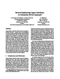
RecordWindow NameLabel NameBox R1
1. Region identification. A view can be seen as a composition of parts or regions (maybe implicit) that give a structure to the widgets that are in the view. Reverse engineering the structure of a view by identifying regions is needed for layout redesign. In the example we can make out three regions in the window. Region R2 contains the widgets that are surrounded by the frame PaymentFrame, and regions R1 and R3 contain the widgets above and below the PaymentFrame respectively (notice that both R1 and R3 are implicit).
SurnameLabel SurnameBox MailButton
AddressLabel AddressBox PaymentFrame
R2
CardLabel
CardCombo
R3
AddButton
DelButton
DiscountLabel ExitButton
Figure 1: View for entering personal information. Widgets are placed with explicit coordinates. RecordWindow: Canvas
a)
CardLabel: Label CardCombo: ComboBox DiscountLabel: Label DiscountCheck: CheckBox PaymentFrame: Frame ...
2. Explicit containment. As explained before, in some cases elements are not actually contained in a container, but they are overlapped. In the example, PaymentFrame surrounds CardLabel, CardCombo, DiscountLabel and DiscountCheck, but these widgets are only visually contained in the frame, that is, in the model their parent element is not PaymentFrame, but RecordWindow (see Figure 2). Both, region identification and explicit containment enable matching the layout ’physical’ and visual structure, what greatly simplifies the reverse engineering algorithms.
RecordWindow: Canvas
b)
PaymentFrame: Frame CardLabel: Label CardCombo: ComboBox DiscountLabel: Label DiscountCheck: CheckBox ...
Figure 2: (a) Fragment of the original GUI tree. (b) The expected GUI tree.
3. Widget structure recognition. While region identification aims at recognizing parts that structure the view, widget structure recognition is focused on how spatially-close widgets are arranged. For example, the widgets inside the PaymentFrame form a line. Widgets are not often perfectly aligned, so heuristics are needed. Following with the example, NameLabel, NameBox, SurnameLabel and SurnameBox could form a line, but it is not clear whether MailButton forms a part of this line.
shared by the GUIs which were built with a RAD environment, as they are the basis to understand them. • GUI builder. GUIs are built using a GUI builder (or designer), by dragging and dropping widgets from a palette. The definition of the interfaces is serialized in files which often use a non-standard format. • Implicit layout. The position of GUI elements (e.g. widgets) is stated by means of coordinates that are relative to the main window or another container. The size of a widget is also given explicitly by the designer. This means that, for example, when a window is resized the widgets are not resized or rearranged.
4. Coordinate abstraction. A coordinate-based positioning system is not desirable, since coordinates are technology-dependant and are not well displayed across technologies. Moreover, they are not flexible enough to perform beautification-wise actions, such as dynamic resizing. A relative positioning-system that represents relationships between elements would be preferable. For example, it is needed to know that NameLabel is above AddressLabel and on the left of NameBox.
• Standard widgets. RAD environments share a common set of standard widgets, such as text boxes, buttons, combo boxes, tables, and so forth. There are container widgets intended to group and/or highlight semantically-related widgets, frequently by means of a border or other kinds of graphical attributes. • Overlapping. Widgets are often loosely contained into a container widget, that is, instead of having explicit containment relationships, they are often overlapped. Containers could also be overlapped on other containers. This means that a container may not contain any widget, although there may be some widgets that would be expected to be contained. For example, in Figure 1, the CardLabel element is not actually contained in the PaymentFrame element, as we can see in the GUI tree in Figure 2. Instead, it is overlapped over the region occupied by PaymentFrame. Discovering view layout is central in our approach to perform reengineering. Our aim is to capture the visual arrangement of elements in such a way that both replicating the layout and redesigning it for a different technology would be easy. Transforming an implicit, coordinate-based layout into an explicit, high-level layout poses the following challenges. The example view in Figure 1 and its partial GUI tree shown in Figure 2 are used to support the explanation.
5. Hole detection. With the term hole we refer to an area of a remarkable size that does not contain widgets but is surrounded by them. In the example view, a hole between DelButton and ExitButton can be found. Capturing layout holes is needed to be able to reproduce a similar layout in a different technology. In the following section we will deal with these problems by means of an MDE approach.
3.
REENGINEERING ARCHITECTURE
A model-based architecture to support the reengineering of a GUI built with a RAD has been devised. It is shown in Figure 3. The process is split in four stages: injection, reverse engineering, restructuring and forward engineering.
3.1
Injection
The first stage in a model-driven reengineering process consists of injecting models from source artefacts, that is, bridging the source technology formalism used to describe the system’s artefacts and the modelware technical space.
Injection
Legacy artefact
Source technology model
Reverse Engineering
Region model
Target code
Tile model
RAD model
Target technology model
CUI model
Forward Engineering
Other UIDL
3.2.1 Restructuring
Figure 3: Model-based architecture to perform reengineering of GUIs built with a RAD. Rounded boxes are models and arrows are transformations. In our architecture, a model-based representation of the legacy GUI is obtained in the form of a Source Technology Model. Such models conform to a metamodel that depends on the specific RAD technology. There are different tools to inject models from source artefacts. The choice will be given by the nature of the artefacts. In our case, we have currently experimented with two source technologies: Oracle Forms and Borland Delphi. In the first case, the GUI description can be obtained in XML format, and injection was performed by means of the EMF [5] tools which generate models (and the corresponding metamodel) from XML conforming to a XML schema. In the second case, GUI source code is written in a simple Delphi-like language, and we used Gra2MoL [3] to inject models based on source code that conforms to a grammar.
3.2
used to gather some information implicitly expressed in the RAD model. The result of the first stage is a Region model, and the result of the second stage is a Tile model. Both models annotate a RAD model with additional layout information that is useful to derive a CUI model in a final stage. Next, we will outline these three stages.
Reverse engineering
The reverse engineering process starts by transforming a Source Technology Model into a RAD model. This is a kind of normalization model for GUIs built with a RAD, in order to make the rest of the process independent of the source technology. The result of the reverse engineering is a Concrete User Interface (CUI) model (following the terminology of the Reference Framework given in [8]), which is a technologyindependent representation of a GUI. Layout is expressed in a CUI model in terms of explicit high-level structures. CUI models can be restructured, and forward engineering can also be applied. A model-to-model transformation chain analyzes a RAD model, gathering information and transforming it into a CUI model. It is worth noting that both RAD and CUI models allow the reverse engineering algorithms to be independent of any technology or platform. The metamodels that define RAD and CUI models (as well as other metamodels and reverse engineering algorithms that will be mentioned later) can be found at http://www.modelum.es/guizmo. Implementation-wise, the reverse engineering algorithms have been implemented in RubyTL [4], which is a rule-based model-to-model transformation language. It provides powerful query facilities, as well as a modularity mechanism, called phasing, that have facilitated the implementation and modularization of the solution. Because of the wide semantic gap that exists between RAD application concepts (included in the RAD metamodel) and our CUI metamodel, we have included two stages prior to the transformation from RAD to CUI models, which are
Detecting regions and containers
This stage is intended to tackle challenges 1 and 2 commented in Section 2. Given a RAD model, a Region model is automatically derived by means of a model-to-model transformation. A Region Model is a model that annotates a RAD model to make explicit the visual containment relationships between widgets. In a Region Model, every GUI element is represented by a region, that is a rectangular area of the GUI which is defined by means of coordinates. Moreover, aditional regions are created to group spatially-related widgets. Region models have three main features: i) every GUI element is associated with a region defined by two pairs of coordinates, ii) container and non-container widgets must not exist at the same level (i.e. a region annotating a container cannot be a sibling of a region annotating a non-container), and iii) overlapped regions are not allowed.
3.2.2
Uncovering relative positions
This second stage is aimed at making the layout independent of the coordinated-based system. It deals with challenges 3, 4 and 5 mentioned in Section 2. The input of this stage is a Region model, and a Tile model is automatically generated. Tile models are mainly focused on representing how widgets and containers are arranged, in terms of relative positions among them. In this model, regions are refined and element position is no longer represented by coordinates. We define a tile as a part of a view with spatial relationships with other neighbour parts (i.e. up, down, left, right). For example, a certain tile could have another tile above it and a different tile below. This positioning system is useful to identify high level layout patterns afterwards, as it will be shown in the next section. Tile models also refine Region models by identifying sub-structures inside regions, for example groups of widgets that form a line.
3.2.3
High level layout
A Tile model solves the layout problems mentioned in Section 2. However, this relative positioning system does not offer a high-level perspective of the layout. For example, in the case of the set of tiles corresponding to the regions R1, R2, R3 in Figure 1 (notice that tiles refine regions), where R1 is above R2 and R3 is below R2, we would not know that they form a pile of tiles unless we analyze the relationships between them. Representing explicitly the structure of the view parts (in terms of stacks, grids, and so forth) is one of the main goals of the CUI Model. CUI models are generated from RAD models by using the annotations included in the Tile models to recognize such layout structures.
3.3
Restructuring and forward engineering
The CUI model is the result of the reverse engineering process. From it, restructuring and forward engineering are possible. Restructuring allows the GUI to be adapted and redesigned (possibly in an automatic way), while forward
engineering allows new software artefacts such as web pages or User Interface Language Descriptions (UIDL) to be automatically generated. We briefly comment on three cases where it enables reengineering activities to be performed: • Layout-preserving migration. Sometimes users are averse to change, hence the original GUI layout must be kept in the new application. Another possible use is to generate a mock application which tracks user input in order to generate test cases [10]. • Reengineering for GUI adaption. Migrating to a new GUI technology requires taking advantage of the target technology features (e.g. usability standards, high-level layout models of modern GUI toolkits, etc.), and in some cases the kind of GUIs that are supported is restricted by the visualization display. • Quality improvement. Perfective maintenance tasks can be required to improve the system quality, such as non-visible widget removal, GUI resizing and beautification [9].
4.
RELATED WORK
There are several works that deal with GUI reverse engineering. An approach to migrate Windows applications to Visual Basic .NET from runtime traces can be found in [6]. No high-level layout information is gathered, so restructuring is not possible. In [11], authors perform static analysis of the source code to identify widgets and recover the GUI tree. In [9], it is shown how to extend hard-coded GUIs to support perfective maintenance tasks. This proposal does not use MDE and is not aimed at migrating applications, but to perform perfective maintenance. Some other works propose reverse engineering of web pages. VAQUISTA [12] is a tool which performs reverse engineering of web pages onto models described with a User Interface Description Language (UIDL). In [2] an approach for extracting web content structure based on visual representation is proposed. It is worth noting that GUI reengineering approaches for web pages work on a DOM tree, which are tree-based representations of the HTML code, where the GUI structure is explicitly expressed by means of HTML tags. In contrast, in a GUI built with a RAD the layout is implicit in the widget coordinates, which requires analyzing the whole GUI. Some UIDL such as USIXML [8] have been proposed, which model platform-independent user interfaces. Tools and generators have also been developed for these languages. Our architecture is able to generate code for these languages, in order to reuse their generators.
5.
CONCLUSIONS AND FUTURE WORK
In this paper we have presented an MDE approach to deal with automatic reverse engineering of GUIs build with a RAD environment. We have analyzed the problem, and we have proposed a model-based architecture to support the reengineering process. The implementation is available at http://www.modelum.es/guizmo. There are three main benefits derived from the use of this architecture. Firstly, automation is highly promoted since the generation of CUI models from RAD models is always automatically performed by means of model-to-model transformations, which is the most complex part of the process.
Secondly, reusability and extensibility are also promoted. To support a new RAD technology, only the corresponding injector plus the transformation to derive RAD models are required. All reverse engineering and restructuring algorithms (i.e. model transformations) and code generators within the architecture are then automatically available. Thirdly, it is maintenable because changes in the reverse engineering algorithms are independent of the source and target technologies (i.e. the RAD and CUI metamodels act as facades). As future work, we will include in our architecture some other aspects related to GUI migration, such as event handling and navigation flows. Moreover, we will deal with configuring the modernization process. We are also interested in exploring to what extent our architecture can be adapted to deal with the migration of web-based GUIs. Finally, new source and target platforms, and new restructuring algorithms will be considered.
Acknowledgments This work is partially supported by Consejer´ıa de Universidades, Empresa e Investigaci´ on (grant 129/2009) and Fundaci´ on S´eneca (project 08797/P1/08).
6.
REFERENCES
[1] L. F. Andrade, J. Gouveia, M. Antunes, M. El-Ramly, and G. Koutsoukos. Forms2net - Migrating Oracle Forms to .NET. In GTTSE, pages 261–277, 2006. [2] D. Cai, S. Yu, J.-R. Wen, and W.-Y. Ma. Vips: a Vision-Based Page Segmentation Algorithm. Technical report, Microsoft Research, 2003. [3] J. L. C´ anovas Izquierdo and J. G. Molina. A Domain Specific Language for Extracting Models in Software Modernization. In ECMDA-FA ’09, pages 82–97, 2009. [4] J. S. Cuadrado and J. G. Molina. Modularization of Model Transformations Through a Phasing Mechanism. Software and System Modeling, 8(3):325–345, 2009. [5] Eclipse. Eclipse Modeling Framework Project (EMF). http://www.eclipse.org/modeling/emf/. [6] J. Gerdes, Jr. User Interface Migration of Microsoft Windows Applications. Journal of Software Maintenance and Evolution, 21(3):171–187, 2009. [7] J. V. Harrison and W. M. Lim. Automated Reverse Engineering of Legacy 4GL Information System Applications Using the ITOC Workbench. In CAiSE’98, pages 8–12, 1998. [8] Q. Limbourg and J. Vanderdonckt. Usixml: A User Interface Description Language Supporting Multiple Levels of Independence. In ICWE Workshops, pages 325–338, 2004. [9] C. Lutteroth. Automated Reverse Engineering of Hard-Coded GUI Layouts. In AUIC 2008, volume 76 of CRPIT, pages 65–73, 2008. [10] A. Memon, I. Banerjee, and A. Nagarajan. GUI Ripping: Reverse Engineering of Graphical User Interfaces for Testing. In WCRE ’03, page 260, 2003. [11] S. Staiger. Static Analysis of Programs with Graphical User Interface. In CSMR ’07, pages 252–264, 2007. [12] J. Vanderdonckt, L. Bouillon, and N. Souchon. Flexible Reverse Engineering of Web Pages with Vaquista. In WCRE ’01, page 241, 2001.