focus
model-driven development
Model-Driven Integration Using Existing Models Peter Denno, Michelle Potts Steves, Don Libes, and Edward J. Barkmeyer, US National Institute of Standards and Technology
s we engineers develop systems, we build models. These models might include business policy guidelines, database schemata, organization charts, class diagrams, and so on. The models span diverse viewpoints and levels of formality. We seldom revisit these models as the enterprise evolves. Often, the modelers themselves have disappeared, and any knowledge that wasn’t captured in the specialized models is inaccessible, forgotten, or written off. Engineers
A
use models even more rarely for later integration efforts, when the systems have been repeatedly patched or have become brittle and the models themselves are often inaccessible, if even applicable. However, can models be more than tools discarded along the way? Might they provide the enterprise with enduring value? Engineers can use these models to automate some systems integration steps that occur as systems evolve. If models can enable automated integration methods, the overall integration costs
While developing software systems, and during the enterprise’s subsequent evolution, developers define models. These models can help automate some systems integration tasks. The joint action model describes a new business transaction that motivates systems integration. US Government Work Not Protected by US Copyright
will decrease and modeling efforts’ enduring value will return because models will become key to a wider segment of the system’s life cycle. Our approach to model-driven integration uses a system’s existing models to characterize how the system’s resources might be used to fulfill requirements for new interactions. Linksacross-views capture the design intent behind legacy systems. They are combined with requirements for new interactions to produce a joint action model. Developers can use the JAM in downstream, automated integration.
Views of business activity In modeling the interactions and communications that let subsystems work together, at least two distinct levels of abstraction are important: conceptual (or business) views and engineering views.
Published by the IEEE Computer Society
IEEE SOFTWARE
59
Integration lets separate components act jointly (cooperatively) toward some goal by enabling message exchange between them.
A conceptual view describes a business’s concepts, rules, and relationships. A conceptual model of cooperative action sees the interacting agents as playing specific roles in the business process, such as buyer and seller or machine controller and source of cutting instructions. The model characterizes the interaction as flows of information and service requests. At a high level, this model might not even assume that the agents are automated. At this level, the model is organized around ■
■
■
Business actions: functions and behaviors that implement each agent’s roles or relate to those functions Business entities: objects discussed in the communications that the cooperative action uses or modifies Transactions: notifications, requests for information, requests for functions or services, and responses
An engineering view of cooperative actions sees the interacting agents as software components communicating through one or more mechanisms, such as file transfer, database access, operation invocation, or queued messaging. For each unit of communication, a mechanism exists, and each agent plays a specific role with respect to that mechanism—for example, file writer or distributed object server. Additionally, for each communication unit, a “message” exists—that is, a set of information that the communication unit transfers. In engineering models, messages have a representation that involves message type, operations, information units, and so on. These should convey the corresponding concepts found in conceptual models. Engineering models may provide a further level of detail that defines the detailed protocols for the communications and the binary representations for each data item. However, since 1990, these details have usually been specified by some standard, and the engineering models simply refer to the appropriate standard for that level of detail.1
Two views of the integration task The system capabilities that are the product of integration are not built into existing components. Rather, the existing components are built with features that support certain capabilities by providing for certain kinds of inter60
IEEE SOFTWARE
h t t p : / / c o m p u t e r. o r g / s o f t w a r e
actions. These features are loosely termed system interfaces. An API, an exchange file, a CORBA interface, and a Web service port are all examples of interfaces in this general sense. Integration lets separate components act jointly (cooperatively) toward some goal by enabling message exchange between them. Being “separate” is what makes components components. Messages bridge the separated components. In a conceptual view, a message advances the business process and informs the cooperating agents. In an engineering view, a message advances the transaction; the mechanism through which we convey the message is a principal concern. System developers conceive solutions to integration tasks in business or conceptual terms and implement them in engineering terms. The solution conception, relying on conceptual models, defines requirements for the engineering implementation. Our method uses conceptual models to describe integration requirements and engineering models to identify elements of potential implementations. Although conceptual views and engineering views serve different roles, we don’t use them in isolation. Consider how engineers do things now, manually. When systems engineers try to satisfy a new requirement for interaction, they examine how they can use existing (engineering) means to achieve their (business) ends. For example, a system supporting sales might be able to provide an item’s cost. To support a certain new customer, however, the system might have to provide the cost value in a form different from the current one.
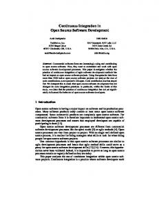
Linking views As the previous paragraph suggests, we use model elements from conceptual and engineering views together. The knowledge that relates those views, however, often exists only in the systems engineer’s mind. Our method defines intermodel relationships called links-acrossviews to relate elements from various models. Links-across-views capture the coherence among conceptual and engineering views. Our method requires us to produce these linked models for each component business entity in the new interaction. Figure 1 shows one such business entity (called Partner A). This entity can request an item’s price through a method getQuote described in a UML Class Diagram. Links-across-views are defined linking
■
■
The request for a quote in a conceptual model with the item’s representation that is a parameter to getQuote (Link 1) The response with the method’s return type (Link 2)
The links establish the relationship between the business activity of requesting a quote and an engineering means of implementing that activity. Links-across-views provide a view that lets the systems engineer focus on those system interfaces that are relevant to the systems’ roles in the joint actions to be implemented. In selecting which links to define, the engineer might be able to ignore much of the existing systems’ modeling because it is irrelevant to the intended joint action. That is, the intended joint action focuses the engineer’s attention on the subset of the interface capabilities that will be useful to integration. This is a further benefit of having system models—the engineer can determine exactly which elements of the existing system he or she needs. In our initial exploratory work, we identified five kinds of links-across-views that help provide coherence among models: ■
■ ■ ■
■
Object-equivalence: link declares that model elements represent equivalent objects or object types. Relation-equivalence: link declares that model elements represent equivalent relations. Activity-equivalence: link declares that model elements represent the same activity. Object-state-during-activity: link declares that the object or object type the model element represents remains in a particular state during a business activity. Activity-partitions-object-type: link declares that the business activity classifies instances of an object type into one or more of its subtypes.
In the example in Figure 1, the links-acrossviews are both object-equivalences.
Describing requirements: The joint action model Systems comprise components, which are themselves systems. In our example, linksacross-views reference only the models of a system of buyers and sellers that are already integrated; they can buy and sell with each other. If new partners—possibly from outside the sys-
Buyer (me)
Seller (you)
Conceptual model Request quote
Respond with quote
item
$
Link 1
Figure 1. Partner A’s view of the system, in which he is a buyer. Sellers use getQuote () to receive quotes. The value returned is a dollarAmt.
Link 2
dollarAmt getQuote(...) Engineering model
tem—become involved in trading, we might need to perform an integration task. The new partner might have business processes and mechanisms for trade, but these could differ from the existing approach. The existing system and the new partners’ trading system become components in a new, expanded system. As the previous section described, our approach’s first step calls for linking engineering models to conceptual models for each participant in the new interaction. The next step produces a conceptual model of the new interaction, describing in conceptual terms the transaction steps and objects referenced. This new model, the joint action model, is a requirements model for the new interaction; it describes what must occur in the business transaction. It does not model either component, nor does it have their scope. Its scope is limited to the required interaction. The JAM uses links-across-views to relate the participants’ views to shared concepts. Links-acrossviews from the JAM to the linked models relate roles in the transaction to resources in the participants’ linked models. The systems engineer manually builds the JAM and the links-across-views to produce an engineering model of the interaction (see Figure 2). We can automate this final step of our approach; the models and composition of links-across-views are used to produce an engineering model that uses the interfaces identified in the engineering models to achieve the goal the JAM describes. September/October 2003
IEEE SOFTWARE
61
Engineering model (automated) Joint action model B
RFQ
S Link
Link
B Conceptual model S Link
B Conceptual model S
Link
Link
Link
B Engineering model S
B Engineering model S
Partner A
Partner B
Figure 2. A joint action model relates the interaction to each participant’s engineering details.
The JAM model specifies exactly which messages the system will use to accomplish the transaction. In the buyers-and-sellers example, the systems engineer might specify, for instance, that Partner A’s getQuote method will be used without modification. Partner B’s existing response to a request for a quote might need modification to service requests in this way. Differences that require information mapping rely on links-across-views between Partner B’s request for quote methods and its product database. Differences in the engineering mechanism (for example, CORBA versus Web services) follow a pattern that is independent of such problem details.
Views, metamodels, and systems engineers When creating the JAM, the systems engineer references elements in the existing systems’ linked models. One significant mistake an engineer can make is to misunderstand what a view communicates. So, when the systems engineer references an element in a linked model, he or she must know what others might infer from that reference. To deal with this problem in our approach, we appeal to the view’s viewpoint. A viewpoint is a discipline for structuring a view (as though the view were an instance of the viewpoint). The discipline defines what details and concerns to capture and to omit. It winnows the view’s audience to those with a particular set of concerns and helps them focus on those concerns. The UML Class Diagram, for example, provides a viewpoint. 62
IEEE SOFTWARE
h t t p : / / c o m p u t e r. o r g / s o f t w a r e
Our approach defines a viewpoint’s intended meaning in the modeling language’s metamodel. To describe notions that generalize across languages, these metamodels reference a model one metalevel higher, similar in purpose to the Meta-Object Facility Model.2 The JAM must provide a view that helps manage the relationship between requirements and discipline-specific system views; this is a principal role for systems engineers.3 Although the JAM’s explicit specification is particular to our approach, aspects of its creation are familiar to engineers. When systems engineers attempt to integrate existing or new systems, they identify elements of the conceptual model that are relevant to the integration activity’s motivating business needs. They might or might not formalize this model, but they must have it in mind. They cast the existing systems into roles in that model. If the engineers can access the existing system’s models, they can more easily determine whether the system was intended to fulfill such a role. Even if the system was not intended expressly for that role, the models describe the system’s functions and communications capabilities and might let the engineers determine that the system is accidentally suited to the role. We compare our method to traditional integration methods in the “Comparisons” sidebar. The advantage of examining models over searching software documentation is connectivity. Graphical models always involve explicit, visible links between concepts that are connected in the same view. Additionally, they contain and emphasize the keywords (object names, events, actions, roles, and associations) that will serve as links to the related concepts in other views. The visible links let us quickly see what’s connected to a concept that is central to a particular integration task and quickly identify the keywords that find the connections in other views. In many cases, the modeling tool itself can deliver a view comprising only the connections to a selected central concept and can thread the links to the same concepts in other views. Additionally, graphical models can be mapped to repositories and queried. Text cannot. This is probably models’ single greatest benefit when we’re developing a new system from a suite of components—they minimize the time and expertise required to match existing components to target roles.
Comparisons We see model-driven integration as a downstream extension of the OMG Model Driven Architecture concept,1 using all levels of MDA models developed during system design. The JAM driving the integration is a computation-independent model (this is MDA terminology for a mechanism-independent model). Our JAM is devoid of engineering decisions partly because implementing the interaction might require using more than one communication mechanism (MDA platform class) and intervening protocol conversion. In MDA, the platform-independent model (PIM) is an engineering model that selects the mechanism and defines the interface’s functional elements. The platform-specific model (PSM) defines a particular protocol’s corresponding implementation elements. This separation of concerns has limited value in modeldriven integration. In defining the engineering model for integration, the critical information is the links-across-views between the JAM concepts and the PSM elements that implement them. In Figure 2 in the main text, when the PIMs in the Partner A and Partner B engineering models are different, we use them to define the local conceptual-model-to-PSM links, but they play no direct role in the integrating engineering model. But in the special case where the PIMs are identical and only the PSMs are different, the integrating JAM is reflected in the common PIM, and the PSM-Ato-common-PIM and common-PIM-to-PSM-B links effectively de-
C
ontinuing system evolution and repeated large-scale and expensive integration are commonplace with virtually all moderately complex software. Traditional integration makes little or no use of the models, which were created at great expense and which provide valuable information about a system. These models can and should be maintained and reused for maintenance and integration. Creating and using joint action models and linked component models, which meld other specialized models, is the key to making the best use of prior investments in model construction. This will significantly ease integration projects by allowing automation of tasks that are presently performed manually.
References 1. E. J. Barkmeyer et al., Concepts for Automating Systems Integration, NIST Internal Report 6928, US Nat’l Inst. of Standards and Technology, Jan. 2003. 2. Meta-Object Facility Specification, version 1.4, Object Management Group, Apr. 2003, www.omg.org/cgi-bin/ doc?formal/2002-04-03. 3. M. Jackson, Software Requirements & Specifications, Addison-Wesley, 1995.
fine the engineering model for the integration—the conversions between the PSM elements that must be implemented. Our approach is similar to how systems are integrated using Enterprise Application Integration tooling.2,3 Such tooling helps engineers develop the interaction’s conceptual model, usually by tailoring a conceptual model that the EAI vendor provides. The tooling then walks the engineer through the process of developing the links-across-views directly to the communicating systems’ engineering models. EAI is a kind of model-driven integration. The difference is that most EAI tooling does not exploit existing models other than those the EAI vendor provides; it does create and archive the component models and interaction models developed under its guidance. We advocate developing and maintaining such models during construction and acquisition of the individual systems, so that engineers can employ the same approach to integration with models that already exist.
References 1. J. Miller and J. Mukerji, eds., MDA Guide, ver. 1.01, Object Management Group, June 2003, www.omg.org/docs/omg/03-06-01.pdf. 2. B. Gold-Bernstein and D. Marca, Designing Enterprise Client/Server Systems, Prentice Hall, 1998. 3. UML Profile and Interchange Models for Enterprise Application Integration (EAI) Specification, Object Management Group, 2002, www.omg.org/ docs/ptc/02-02-02, 2002.
About the Authors Peter Denno is a computer scientist at the US National Institute of Standards and Tech-
nology. His research interests include information modeling and systems engineering. He received his BS in mathematics from the University of Connecticut. Contact him at the Nat’l Inst. of Standards and Technology, 100 Bureau Dr., Gaithersburg, MD 20899;
[email protected].
Michelle Potts Steves is an information systems analyst at the National Institute of Standards and Technology. Her research interests include computer-supported cooperative work, software usability evaluation, and information modeling. She received her BS in mathematics and computer science from Western Maryland College. Contact her at the the Nat’l Inst. of Standards and Technology, 100 Bureau Dr., Gaithersburg, MD 20899;
[email protected].
Don Libes is a computer scientist at the National Institute of Standards and Technology.
His research interests include interaction integration automation and national broadband policy issues. He received his MS in computer science from the University of Rochester. Contact him at the Nat’l Inst. of Standards and Technology, 100 Bureau Dr., Gaithersburg, MD 20899;
[email protected].
Edward J. Barkmeyer represents NIST on national and international standards bod-
ies in the areas of interface specification, information modeling, and data interchange for manufacturing software. He is currently leading a project in automating software integration processes using systems engineering and artificial intelligence methods. He received his MS in applied mathematics from the University of Maryland. Contact him at the Nat’l Inst. of Standards and Technology, 100 Bureau Dr., Gaithersburg, MD 20899;
[email protected].
For more information on this or any other computing topic, please visit our Digital Library at http://computer.org/publications/dlib.
September/October 2003
IEEE SOFTWARE
63