The software development community pursues the development of software ... been reported that leader companies release next to a hundred new products a.
Model driven testing in Product Family Context Juan C. Dueñas, Julio Mellado, Rodrigo Cerón, José L. Arciniegas, José L. Ruiz, Rafael Capilla Department of Engineering of Telematic Systems, Universidad Politécnica de Madrid, ETSI Telecomunicación, Ciudad Universitaria, s/n, E-28040 Madrid, Spain 1
{jcduenas,ceron,jlarci,jlruiz}@dit.upm.es http://www.dit.upm.es/
Abstract The software development community pursues the development of software systems with a higher degree of reuse, reduction of costs, and shorter time to market. One of the successful mechanisms followed to achieve these goals is based on sharing the development efforts, producing sets of similar products. This approach is known as Product Family Engineering (PFE). Although the concept is a fertile ground for the application of the Model Driven Engineering, up to date testing activities have been little addressed. This paper contains a proposal of metamodel for testing, based on the UML profile for testing, but capable of being used in a Product Family Engineering context, where the identification and modelling of both the parts that are shared by all the products in the family, and those that are specific to any product is a must. The work is based on some of our experiences in the application of this approach in several industrial fields.
1.
Introduction
In software intensive systems, especially in those domains closer to consumer electronics (these domains are expected to continue a path of growing in the next years), the size of the product portfolio that a company must deliver to the market is increasingly larger. The case, for example, of mobile phones is significant enough: it has been reported that leader companies release next to a hundred new products a year. It is sensible to think that there are no major changes in functionality to all those products; rather, functionality advances in small "deltas", as improvements to the functions, introduction of new ones (in incremental steps), and bug repairs. Besides, although mobile phones software and services are not considered critical systems, the quality of the products is important to keep the market share and therefore in the development many efforts are focused on testing the new products. From the technical side the situation reveals to be critical because the changes introduced into a new product with respect to the previous one need to be tested in relation to all the previous functions. As an example, if a new feature is added to the agenda of the mobile phone, it should be tested while calls are coming, or at the same time the user is trying to create a message. This is to explain the difficulties and that the number of new tests do not grow linearly with changes, but closer to an exponential line. To put it in a nutshell: changes in functionalities of these systems are delivered in an incremental way, there are many related but different systems, testing is the main activity in the development process dealing with the quality of products. We will see more and more attention paid to testing in the short term. More testers are required, and improvements to the techniques used so far to testing are needed in order to meet the time to market of new products. The proposal of this paper is that the application of the basic principles of model driven engineering or model driven architecture, this is, using models, separing the specification from realisation models, describing the transformations, can be used in the context of testing of these software intensive systems. That the approach is useful in other domains where system families or product lines are set, provided a clear metamodel and methodologycal support is available. The rest of our contribution is organised as follows: the second section is devoted to present the principles of system families engineering, with special focus in the difference between family and product
91
engineering. The third section includes information specific to testing and the usage of MDA models in this development phase. Fourth section reports our experiences in the application of this approach. Conclusions and information about our further work is included.
Figure 1 CAFÉ Process Reference Model. The basic work behind the results presented here has performed in the CAFÉ and FAMILIES projects [1]. The CAFÉ reference framework (CRF) gives a guide to classify the activities and models related with PF development. In summary, CRF can be divided in two main parts CAFÉ Process Reference Model (CAFÉ – PRM, shown in Figure 1) and CAFÉ Assets Reference Model (CAFÉ - ARM). The objective of this model is to represent the major activities and methods operating on the core assets, to allow the mapping of the contribution/tools against a common reference. Our research work is aimed to solve problems in the transition from Domain Testing to Application Testing, although the transitions in other phases of development are also considered in our research work. The product family can be described by several types of models [2] for requirements, architecture, design, and test. The requirement models deal with the functional but also non-functional features for the products in the family. The architectural models describe high-level design definitions of the products in the family; the design models show the different components that the architectural models describe; and finally, test models contain the tests that the PF must satisfy; they are usually based on the PF requirements. Our goal in this document is to present our ongoing efforts towards the representation and efficient management of product family testing by means of the model driven approach, which includes: • The clarification of the methodological approach for the introduction of model-driven testing in the product family context. • The identification of a testing metamodel able to be used in practice in the product family context, and close to the OMG-UML testing profile. • The selection of modelling mechanisms capable to represent the shared and the variable parts in the tests in usable and efficient way. • The identification of derivation mechanisms that cover the transformation of product family tests into product specific tests.
2.
Validation aware development process for product families Domain Use cases Scenarios
Requirements Analysis Design
Derived Test cases Derived Test cases Derived Test cases Derived Test cases
System test and derived subsystems System Test Integration Test Unit Test
Implementation
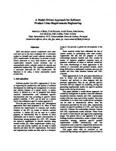
Figure 2: The V model for product family engineering.
92
The figure represents the well-known V development model: it is a classical model that maps validation and verification activities (testing) onto the waterfall model. Applied to product family engineering, however, there are two tracks for testing. The first one (represented in the medium branch of the doble-V model) contains the parts of the testing models that are shared by all the products in the family, this is, the reference testing models. As can be imagined, these models are abstract, and are, in general, mainly addressed to the testing of the platform in case there is a component platform supporting the family, also mainly addressed to integration testing (that performed putting several parts of the final system together, not just testing an isolated component). Also skeletons for testing of functions shared by all the products in the family are contained here. That is about test definition; only a small part of them can be actually performed or executed, since they require a large infrastructure in terms of stubs to be properly executed. The right branch of the model depicted in figure 2 corresponds to the second testing track, that takes the test cases that are shared by all the products in the family, adapts them if necessary to be applied on a particular product, adds new tests (those that are specific to each product), and is able to execute all these tests on actual products. Thus, this branch contains actual detailed tests, their execution and their results. The fact we found in our experiments is that this situation corresponds nicely to the basic principles of the Model Driven Engineering and Model Driven Architecture methods: the family referenced tests (or testing models) are platform independent, even more, product independent, while the actual tests to be performed on specific products are platform and product specific. In the same way that MDA tries to clarify the mapping between the PIM and the PSM, the application of testing models in the product family engineering approach requires a method to describe the models, and a way to perform the correspondence between them. Trans ition S t ate
S tate Trans ition Di agram s
nam e
Input S tate Outp ut S tate Require m ent E vent
A trans ition is related with one r equirem ent or m ore
s pec ified b y Tes t Cas e Requirem ents
tes ted b y 1..*
Tes t Clas s Nam e
Requirem ents Coverage c ontains Input E x pec ted Res ult E vent
Tes t Data im plem ents
Input E x pec ted Output E vent
s pec ified b y Generic
Cus tom er S pec ific
Tes t S cenarios (S CE N) Des c ription Initial S tatus E vent E x pec ted S tatus Requirem ents Coverage
A n s c enario is related with one requirem ent or m ore
Figure 3: Meta-model for testing. Most of the benefits promised by MDA would in this situation be applied to testing, with the difference that while the concept of architectural models is already an industrial issue accepted in many companies and performed with the help of tools, testing is still in an immature stage, most of it is made by hand, and no widespread agreement on notations have been reached yet. The application of MDE can help in the organisation of testing activities, and in the introduction of models in this phase of development. The metamodel for testing we present shortly is a conceptual framework able to cope with variability in testing [3], so, although it follows the general principles stated by the UML profile for testing [4], modifies and extends the profile in several aspects. In particular, our metamodel includes some elements already available in the profile, such as Test Case, Test Class (that is called Test Suite), and the concept of Test Data. The mapping of the Test Class to State Transition Diagrams is however, unique in our approach, as well as the relation to the Requirements model. The Fig. 3 shows the main entities of the test approach and their relationships. The requirements are the basis of the test; in particular, requirements (both generic in the system family and specific to a subset of systems in the family) drive the design of test classes. A test class is a group of test cases related with a certain system entity. These test cases are derived from a model of the behaviour of this entity based on State Transition Diagrams and Test Scenarios. For example, the test Class Track Circuit includes all the test cases related with this element in a reference architecture for train control. Test cases include
93
requirements traceability information. This information makes possible to evaluate the requirements coverage (how many requirements are tested). Fig. 4 shows the workflow of activities in the validation, from the test design to the test execution. The process starts with the requirements specification. Domain experts build testable models with the information of the requirements, the state transition diagrams and the test scenarios.
PF Selection PF Requirements [initial]
Product Requirements [initial] Test Case Repository
Product Requirement Derivation
Product Requirements [initial] Desicions [initial]
Test Case Selection
PF State Chart Selection
Product SpecificTest Case [initial]
Desicions [initial]
Event and State Tables
Product State Chart Derivation
Execution
Event and State Tables [initial] Test Case Results
Figure 4: Activities in derivation of product specific tests. State transition diagrams describe the behaviour of the system elements. At this level, a transition is defined by an input state, an output state, an event that triggers the transition and a set of system requirements that are associated with the transition. This makes possible to measure the requirements coverage. It is also possible to know which test cases are covering generic requirements and which ones customer specific requirements. The test scenarios are used for representation of complex requirements involving several entities of the system. There are system requirements that are not specific of a single test class.
3.
Variability management
In order to know how to face variability, first we need to understand it. A definition may help: “Variability is what can be different among members of a collection (of problems, solutions or products)” [5]. Variability aspects can be managed at different stages: requirements descriptions, test scripts, architectural models, design documentation, source code, compiled code, linked code and running code. The variation point concept can be used in order to express variability explicitly. A variation point identifies one or more locations at which variability will occur. Each variation point will be related to a decision [6]. Once the decision is made, a set of variant elements will remain and others will be left apart; as a result, the variation point will have changed its state. This principle, which has extensively applied in the architectural process [7], is now proposed to be applied to testing models. Tightly linked to the concept of variability, the decisions are part of the product family; therefore they are related to the models in the PF. In order to obtain specific products, decisions have to be taken to deal with variability: either in the requirement, or architectural or testing phases. The later the variability issues are solved the more flexible the product family is. Conflicts are a consequence of the variability in the product family; they have to be fixed in order to obtain coherent products. Different alternatives may lead to different conflicts, but there should be at least one solution for each conflict. Variability is explicitly represented in the testing models through variation points. For us, each variation point is composed of one or more variants and it is formally defined by an algebraic expression. The expression denotes the relationships among elements, using as syntax operators the ones available in Boole Algebra. Expressions are composable, therefore an expression can be created as a combination of others. While the variation point concept appears several times in the literature, attaching logical
94
expressions about the composability of the different variants is a novel contribution of ours. Due to its expressivity power, simplicity and independence of the modelling language used, we consider this solution very useful in real, industrial contexts. is composed of
Product Family
1..* Product
1 belongs to
1..*
1
(from Requirements Model )
has
1
isGoal : Boolean isFeature : Boolean isConstraint : Boolean 1..*
belongs to
Product Requirement
PF Requirement (from Requirements Model )
1..n
1
belongs to 1..* belongs to
0..*
has
isGoal : Boolean isFeature : Boolean 1 isConstraint : Boolean
PF Requirement Property (from Requirements Model )
1..*
1 PF Volatility
PF Prioritisation
(from Requirements Model )
(from Requirements Model )
1..*
Product Requirements Property (from Requirements Model )
0..*
1
Product Prioritisation
Product Volatility
(from Requirements Model )
(from Requirements Model )
0..1 * 0..* Variant Transition
Variant State Machine
(from Test Model)
(from T est Model)
1
1
Variant Event (from Test Model)
0..*
Variant State (from Test Model)
1..*
0..* derived from
1 derived from
derived from
derived from
1..* 1
Transition (from T est Model)
1
State Machine (from Test Model)
1..*
*
1..*
0..*
1
(from Test Model)
contains 1
Test Case 1..*
Event (from Test Model)
1
1 Test Class
tested by
0..* 0..1
1..*
1
specified by
State (from Test Model)
1
Test Data
(from T est Model)
1
(from Test Model)
implements
1..n
Figure 5: The extended metamodel, requirements traceability and variability. Thus, these variation points, considered as the possibilities of selection of variable parts in test cases, classes and scenarios, together with the decisions taken about the variability, guide the derivation of actual tests for the specific product in the product family. Figures 6 and 7 present a typical case in which a statechart describes a generic test case, applicable to all the products in the product family but with a restriction (the variation point is represented by the Boole algebra expression “requirementVVV XOR requirementWWW”, that means that an exclusive selection must be taken in order to convert the generic test into a product specific one). For testing, part of the decisions can be traced to the requirements actually selected for the specific product (henceforth the names) and have been made previously. The decisions that must be taken and are specific to the testing phase are mainly related to the testing scenario and test data (reflected in the testing metamodel). EventBB( RequirementZZZ )
EventBB( RequirementZZZ )
EventAA( RequirementZZZ )
EventAA( RequirementZZZ )
State A
State B
EventAB( RequirementZZZ )
State A
event Initial/ ^EventB(RequirementYYY)
event Initial/ ^EventA(RequirementXXX)
State B
EventAB( RequirementZZZ )
event Initial/ ^EventB(RequirementYYY)
event Initial/ ^EventA(RequirementXXX)
EventCB( RequirementVVV ) EventAE( RequirementYYY )
EventAC( RequirementVVV ) {variant}
EventAE( RequirementYYY )
State C {variant} State E
event Initial/ ^EventV(RequirementVVV)
State E
event Initial/ ^EventE(RequirementYYY)
event Initial/ ^EventE(RequirementYYY)
EventAD( RequirementWWW ) {variant}
EventDB( RequirementWWW ) EventAD( RequirementWWW )
State D {variant} EventED( RequirementWWW ) {variant}
EventDB( RequirementWWW ) State D
event Initial/ ^EventD(RequirementWWW) EventED( RequirementWWW )
event Initial/ ^EventD(RequirementWWW)
EventFB( RequirementYYY ) EventEF( RequirementZZZ )
EventFB( RequirementYYY )
State F event Initial/ ^EventF(RequirementZZZ)
RequirementVVV XOR RequirementWWW
Figure 6: Statechart for reference test.
EventEF( RequirementZZZ )
State F event Initial/ ^EventF(RequirementZZZ)
RequirementWWW Selected
Figure 7: Statechart for specific test.
Figure 7 represents the test case after both the requirements and the testing decisions have been taken, and the derivation of the actual test case takes place. In this particular case, the only variability is linked to transitions in the statechart by means of references to requirements. The transformation is simply in this case removing transitions in the statechart and checking that the final one is correct; afterwards we use some well-known state space exploration techniques in order to create a test script.
95
4.
Conclusions and further work
The approach taken is based on the best practices studies and described during the ESAPS, CAFÉ and FAMILIES projects, by partners interested in the application of product family engineering in the industrial setting. There are some other studies close to ours in the literature that show the potential for the description of the variation points as a “full right citizen” in the models for the product family. Ours makes a strength focus on the description of variation points as relations between model elements and not overloading the UML models with new constructs; the representation of decisions linked to the variation points and to the models; and the automatic generation of the test cases that fit to the decisions taken by designers. Thus, the approach is close to the MDA proposals. Our future work in this field will be devoted to the validation of the approach by use in more industrial case studies (it has been applied to a real case in the field of train control and on several experimental prototypes for network management systems). Development of the operational support (adaptations to currently available tools) in order to automate the derivation process is also work in progress. Finally, the provision of the methods for the easy adoption of this approach for organisations that have already made a large investment in testing should be addressed.
References [1] van der Linden, F.: Software Product Families in Europe: The Esaps & Café Projects. IEEE Software, July 2002. [2] Bosch, J.: Design and Use of Software Architectures-Adapting and Evolving a Product Line Approach. ACM Press, Addison-Wesley, 2000 [3] Coplien, J., Hoffman, D., Weiss, D.: Commonality and Variability in Software Engineering. IEEE Software, November 1998. [4] OMG, UML Testing Profile (final submission) by Ericsson, IBM, Fokus, Motorola, Rational, Softeam, Telelogic. March 2003. [5] Keepence, B., Mannion, M.: Using Patterns to Model Variability in Product Families. IEEE Software, July 1999. [6] Alonso, A., León, G., Dueñas, J.C., de la Puente, J.A.: Framework for Documenting Design Decisions in Product Families Development. Proceedings of the Third IEEE International Conference on Engineering of Complex Computer Systems, IEEE Computer Society, 1997. [7] Jazayeri, M., Ran, A., van der Linden, F.: Software architecture for product families. Addison Wesley, 2000
96


![[PDF] Lessons Learned in Software Testing: A Context Driven ...](https://m.moam.info/img/260x300/pdf-lessons-learned-in-software-testing-a-context-_6478a172097c474c228d58ac.jpg)