International Journal of Power Electronics and Drive System (IJPEDS) Vol. 7, No. 3, September 2016, pp. 973~985 ISSN: 2088-8694, DOI: 10.11591/ijpeds.v7i3.11065
973
Modeling and Control of a Doubly-Fed Induction Generator for Wind Turbine-Generator Systems Mouna Lamnadi*, Mourad Trihi*, Badre Bossoufi**, Abdelkader Boulezhar* * Department of Physics, Theoretical and Applied Physics Laboratory, University Hassan II Ain Cock Faculty of Sciences, Casablanca, Morocco ** Laboratory of Electrical Engineering and Maintenance, Higher School of Technology, EST-Oujda, University of Mohammed I, Morocco
Article Info
ABSTRACT
Article history:
This paper presents a vector control direct (FOC) of double fed induction generator intended to control the generated stator powers. This device is intended to be implemented in a variable-speed wind-energy conversion system connected to the grid. In order to control the active and reactive power exchanged between the machine stator and the grid, the rotor is fed by a bi-directional converter. The DFIG is controlled by standard relay controllers. Details of the control strategy and system simulation were performed using Simulink and the results are presented in this here to show the effectiveness of the proposed control strategy.
Received Nov 12, 2015 Revised Apr 12, 2016 Accepted May 13, 2016 Keyword: DFIG Simulation Vector control direct Wind energy
Copyright © 2016 Institute of Advanced Engineering and Science. All rights reserved.
Corresponding Author: Mouna Lamnadi, Department of Physics, Theoretical and Applied Physics Laboratory, University Hassan II Ain Cock Faculty of Sciences, Km 8 Route d'El Jadida ,B.P 5366 Maarif Casablanca 20100 Morocco. Email:
[email protected]
1.
INTRODUCTION In the recent years, renewable energy systems have attracted the great interest because conventional sources of energy are limited and a number of problems associated with their use, like environment pollution, large grid requirements etc. Governments of the whole world are forced for the alternative energy sources such as wind power, solar energy and small hydro-electric power [1] Morocco, as well as globally, being one of largest energy importer in MENA, is making concerted efforts to reduce its reliance on imported fossil fuels. Renewable energy is an attractive proposition as Morocco has almost complete dependence on imported energy carriers. In 2012, Morocco spent around US$10 billion on all energy imports (crude oil and oil products, coal, natural gas and electricity). Annual electricity consumption in Morocco was 33.5 TWh in 2014, and is steadily increasing at a rate of around 7 percent each year [2, 3]. Morocco has huge wind energy potential due to it 3,500 km coast line and average wind speeds between 6 and 11 m/s. Regions near the Atlantic coast, such as Essaouira, Tangier and Tetouan (with average annual average wind speeds between 9.5 and 11 m/s at 40 metres) and Tarfaya, Laayoune, Dakhla, and Taza (with annual average wind speed between 7.5 and 9.5 m/s at 40 metres) has excellent wind power potential. According to a study by CDER and GTZ, the total potential for wind power in Morocco is estimated at around 7,936 TWh per year, which would be equivalent to about 2,600 GW. Morocco’s total installed wind power capacity at the end of 2015 was an impressive 787MW.
Journal homepage: http://iaesjournal.com/online/index.php/IJPEDS
IJPEDS
ISSN: 2088-8694
974
Wind energy is the current “star” in the field of renewable energy for electrical production. Still, the power generated by wind turbines over time is characteristically uneven due to the unpredictable nature of their primary source of power. In fixed speed wind energy conversion system often uses from squirrel-cage induction generator that is connected to grid directly. This machine has maximum efficiency at certain speeds. In variable speed generating systems, at the beginning, squirrel cage induction generator was used with back to back converter. This converter controls total power passes through the generator and it raises the cost. Today’s, doubly- fed induction generator (DFIG) is most suitable for variable-speed constant frequency generating [4, 5]. The Control of DFIG wind turbine systems are traditionally based on either stator flux oriented control (FOC) [6] or stator voltage oriented control (VOC) [7]. The Doubly-Fed Asynchronous Generator (DFIG) with FOC control is a machine that has excellent performance and is commonly used in the wind turbine industry. There are many reasons for using an Doubly-Fed Asynchronous Generator (DFIG) for wind turbine a variable speed, such as reducing efforts on mechanical parts, noise reduction and the possibility of control of active power and reactive [10]. The wind system using DFIG generator and a "back-to-back" converter that connects the rotor of the generator and the network has many advantages. One advantage of this structure is that the power converters used are dimensioned to pass a fraction of the total system power [8-9]. This allows reducing losses in the power electronics components. The performances and power generation depends not only on the DFIG generator, but also the manner in which the two parts of "back-to-back" converter are controlled [11]. The power converter machine side is called "Rotor Side Converter RSC" (PWM Inverter 1) and the converter Grid-side power is called "Grid Side Converter GSC" (PWM Inverter 2). The RSC converter controls the active power and reactive power produced by the machine. As the GSC converter, it controls the DC bus voltage and power factor network side (Figure 1).
Figure 1. Architecture of the Control
2. WIND ENERGY SYSTEM 2.1. Modelling of the Wind-Turbine By applying the theory of momentum and Bernoulli's theorem, we can determine the incident power (theoretical power) due to wind [12]:
1 Pincident ..S.v3 2
(1)
S : the area swept by the pales of the turbine [m2] ρ : the density of the air (ρ =1.225kg / m3 at atmospheric pressure). v : wind speed [m/s ] Due to various losses in wind energy system, available on the power extracted from the turbine rotor, is lower than the incident power. The power extracted is expressed by [13]:
1 Pextracted ..S.C p (, ).v3 2
(2)
Modeling and Control of a DFIG for Wind Turbine-Generator Systems (Mouna Lamnadi)
975
ISSN: 2088-8694
Cp (λ, β) is called the power coefficient, which expresses the aerodynamic efficiency of the turbine. It depends on the ratio λ, which represents the ratio between the speed at the end of the blades and the wind speed and the angle of orientation of the blades β. The ratio λ can be expressed by the following relation [13]:
t .R v
(3)
The maximum power coefficient Cp was determined by Albert Betz (1920) as follows:
C pmax(, )
16 0.593 27
(4)
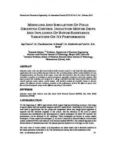
The power factor is intrinsic to the constitution of the wind-turbine and depends on the profiles of the blades. We can model the power coefficient with a single equation that depends on the speed ratio λ and pitch angle β for the blade [13]: 1
1 c5 C p (, ) c1. c2 . c3 . c4 .e A c6 . A
(5)
c1= 0.5872, c2= 116, c3 = 0.4, c4= 5, c5 = 21, c6= 0.0085 The six coefficients c1, c2, c3, c4, c5 are modified for maximum Cp equal to 0.498 for β = 0°. With A which depends on λ and β:
1 1 0.035 A 0.08. 1 3
(6)
The Figure 2 shows the curves of the power coefficient as a function of λ for different values of β. A coefficient of maximum power of 0.498 is obtained for a speed ratio λ which is 8 (λopt). Fixing β and λ respectively to their optimal values, the wind system provides optimal power [14-15].
Figure 2. Power coefficient as a function of λ and β
Figure 3.Wind-turbine DFIG characteristics IJPEDS Vol. 7, No. 3, September 2016 : 973 – 985
IJPEDS
ISSN: 2088-8694
976
The aerodynamic torque on the slow Wind-turbine DFIG characteristics axis can be expressed by Equation 7: [16-17]
Cal
Peol 1 1 ..S.C p (, ).v3. t 2 t
(7)
Ωt : Rotational speed of the turbine. Cal : Torque on the slow axis (turbine side). The mechanical speed is related to the speed of rotation of the turbine by the coefficient of the multiplier. The torque on the slow axis is connected to the torque on the fast axis (generator side) by the multiplier coefficient. The total inertia J is formed of the reduced inertia of the turbine and the fast axis of the inertia J of the generator [16]:
J
JTur Jg G2
(8)
JTur : Turbine inertia. Jg : Inertia of the generator. To determine the evolution of the mechanical speed from Cmec total torque applied to the rotor of the DFIG, we apply the fundamental equation of dynamics:
J
dmec Cmec Car Cem f .mec dt
(9)
Ωmec : Mechanical speed of DFIG. Car : Aerodynamic torque on the fast axis of the turbine. Cem : Electromagnetic torque. f : Friction. The above equations are used to prepare the block diagram of the model of turbine (Figure 4).
Figure 4.Wind-turbine model
2.2. Extraction of Maximum Power In order to capture the maximum power of the incident energy of the wind-turbine, must continuously adjust the rotational speed of the wind turbine. The optimal mechanical turbine speed corresponds has λopt and β = 0°. The speed of the DFIG is used as a reference value for a controller proportional-integral type (PI phase advance). The latter determines the control set point which is the electromagnetic torque that should be applied to the machine to run the generator at its optimal speed [18]. The torque thus determined by the controller is used as a reference torque of the turbine model (Figure 5). The system of variation of the angle of orientation of the blades (variation of the angle of incidence) to change the ratio between the lift and drag. To extract the maximum power (and maintain constant), the adjusted angle of incidence of the blades to the wind speed [19-20]. The "Pitch Control" is a technique that mechanically adjusts the blade pitch angle to shift the curve of the power coefficient of the turbine. However, it is quite expensive and is generally used for wind turbines and high average power. For our model, the "Stall Control" technique, which is a passive technique that allows a natural aerodynamic stall Modeling and Control of a DFIG for Wind Turbine-Generator Systems (Mouna Lamnadi)
977
ISSN: 2088-8694
(loss of lift when the wind speed becomes more important). Otherwise, β is zero. The synthesis of the PI controller requires knowledge of the transfer function of our system. This is especially difficult because of the power coefficient. A simple proportional correction (P) is obtained after testing. Note that β may vary from 0 ° to 90 ° characterized by saturation.
Figure 5. Block diagram with control of the speed
2.3. Model of the Doubly Fed Induction Generator For a better representation of the behavior of a doubly fed induction generator, it is necessary to use a specific model and simple. The two-phase models (d, q) given by the Park transformation is used. 2.3.1.
The electrical equations of DFIG The equations of the stator voltages Vs (d, q) and the rotor Vr (d, q), the dynamic model are expressed by DFIG [5]: Vsd V sq V rd V rq I sd I sq I rd I rq
d sd dt d sq dt drd dt drq dt
Rs .I sd
s . sq
Rs .I sq
s . sd
Rr .I rd Rr .I rq
1
. sd
1
. sq
1
.rd
1
.rq
.Ls .Ls .Lr .Lr
(10)
r .rq r .rd
M sr
.Lr
. sd
M sr
. sq
M sr
. sd
M sr
. sq
.Ls .Lr .Lr .Ls .Lr .Ls
(11)
2.4. The magnetic equations The following magnetic equations are taken from electrical equations (11):
sd sq rd rq
Ls .I sd M sr .I rd Ls .I sq M sr .I rq Lr .I rd M sr .I sd Lr .I rq M sr .I sq
IJPEDS Vol. 7, No. 3, September 2016 : 973 – 985
(12)
IJPEDS
ISSN: 2088-8694
978
2.5. The mechanical equation The electromagnetic torque of the DFIG is:
Cem P( rd . sq rq . sd )
(13)
with: φs(d,q), φr(d,q) : Stator and rotor two-phase flow in the reference of PARK. Is(d,q), Ir(d,q) : Stator currents and rotor in the reference of PARK. Rs, Rr : Stator and rotor resistances. Ls, Lr : Inductors cyclic stator and rotor. M: Cyclic mutual inductance. p : Number of machine pole pairs. ωs: Pulsations of the stator electrical quantities. ωr: Pulsations of the rotor electrical quantities.
3. VECTOR CONTROL OF DFIG BY ORIENTATION FLUX ROTOR In this work we have proposed a vector control law for DFIG based on the orientation flow rotor. In this respect, it demonstrates the relations between the stator and rotor variables. These relations will allow the rotor to act on signals to control the exchange of active and reactive power between the rotor of the machine and the grid. In this control, the flow rotor is oriented in the direction axis d. Thus, we can write:
rd r ;rq 0
(14)
The expression of the flow rotor and the stator then becomes: sd sq rd rq
Ls Lr LsI rd M sr rd M sr Lr .Ls . .I rq M sr M sr .I M 0
(15)
The expression of the electromagnetic torque then becomes:
Cem P(rd .sq ) Lr .Ls . .I rq.I M
(16)
From the previous equation, we can derive the equations linking the rotor and stator voltages: RR L L s r Rr Ls Rs Lr Lr Ls dIrd s s r L R r Vsd Ird . Irq s Vrd s Vrq M M dt M M sr sr sr sr r M sr s Rr Ls Rs Lr L L dI L L r V Irq r s . rq s . r LsIrd s s Vrq sq M sr M sr dt M sr r M sr
(17)
RR s Ls Lr s r M sr Rr Ls Rs Lr Lr Ls dIrd R r Vrd ( I rd . I rq s Vrq Vsd ) Ls M sr M sr dt M sr r M sr s Rr Ls Rs Lr r M sr r L L dI L L ( I rq r s . rq s . s r I rd Vsq ) Vrq L M M dt M sr s s sr sr
Modeling and Control of a DFIG for Wind Turbine-Generator Systems (Mouna Lamnadi)
979
ISSN: 2088-8694
The vector control the DFIG allows us to express the expressions of active and reactive power as followings: Pr Vrd .I rd Vrq.I rq Qr Vrq.I rd Vrd .I rq
(18)
We replace the Vrd and Vrq tensions in Pr and Qr Qr are obtained: 2 2 Pr Rr I rd Rr I rq rrd I rd Qr rrd I rd
(19)
The power Pr is proportional to the current Irq if the flow is kept constant. We can then write:
Pr Prj KIrq Qr KIrd
(20)
The variables references values are defined to control. Thus we have the rotor currents reference. P*r K Q*r K
I *rq I *rd
(21)
3.1. Current Control The current control ensures voltage regulation of the DC bus and control power factor of the grid side. The objective of the control is to maintain the voltage of DC bus constant while absorbing a current to be sinusoidal as possible, with the possibility of the grid side the power factor adjustment. The grid side converter is controlled such that the active power and reactive power grid side are written as follows [6]: 3 U m .I d 2 3 Q U m .I q 2 P
(22)
With, Um is the amplitude of the phase voltage. Applying the mesh law, we obtain the tension of the filter is written in matrix form in the "abc" plan.
V1 I1 I1 dn1 d V2 Rr I 2 Lr I 2 dn2 .Vdc dt V I 3 3 I 3 dn3
(23)
This gives the differential equation of continuous DC bus:
dVdc 1 (2dn1 dn2 )I1 (dn1 2dn2 )I 2 dt Cdc With: dVdc Cdc dt I dc I I1 I 2 et 3 3 dn3 dn1 dn2 I dc dnmI m m 1
IJPEDS Vol. 7, No. 3, September 2016 : 973 – 985
(24)
IJPEDS
ISSN: 2088-8694
980
The representation status of an inverter in the plan 'abc' is non-linear (variable in time). We use the PARK transformation plan “dq” to facilitate implantation and extraction of harmonics:
V1 d n1 I1 d nd Id Vd P( )V2 ; P( ) d n2 ; P( ) I 2 Vq dnq Iq V d I 3 n3 3
P( ) : Matrix Park By applying the Park transformation to equation (22) and (23) we find the following relation dId Vd Rr I d Lr dt d nd .Vdc LrI q dIq d nq .Vdc LrI d Vq Rr I q Lr dt 1 dVdc dt C d nd I d d nq I q dc
(25)
The variables references values are defined to control. These are the reference voltages for the inverter. * V d Vd U d eq * V q Vq U q ed
With:
dId U d Rr I d Lr dt ed LrI q and eq LrI d U R I L dIq r q r q dt The general structure of the flow rotor orientation in a wind system is detailed in the figure below:
Grid
* Vdc
+
* P
-
V dc
* Qr
* Q 1/((3/2)Um)
-1/((3/2)Um)
* Id
* Iq
-
I rd
* Pr 1/ωrϕrq * I rq
+-
Iq
+
-
+-
+
Id
1/ωrϕrd * I rd
I rq
Rotor Uq
U rd
Converter side Grid V* d
U rq
DFIG
Rotor side converter
V* q
V* rd
Park dq => abc
Stator
V* rq
DC =
R R R
AC ≈ Inverter
DC = C
Multiplier Shaft
ϴs
Park dq => abc
-
ϴr
Turbine
+
Ud
ϴm
ϴ
AC ≈ Rectifier
Figure 6. General structure of the orientation control the flow rotor applied to a wind system
Modeling and Control of a DFIG for Wind Turbine-Generator Systems (Mouna Lamnadi)
981
ISSN: 2088-8694
3.2. Simulation and Test Performance & Discussion The following Figure presents the global model of the wind system is simulated in the Matlab/ Simulink/. The model consists: the wind turbine, the doubly fed induction generator (DFIG), two power converters that connect the rotor to the grid: [wr]
Omega_g beta
[wr]
wr
Tm beta
Tm
t1
[Idq_r]
Idq_r Wind speed (m / s)
Wind speed (m / s)
Vabc
Wind Turbine Vabc P_ref
Idq_s
[Idq_s]
Vdq_s
[Vdq_s]
Vdr
P_ref Vdr
Q_ref
Q_ref
P_Grid
P_Grid
Q_Grid
Q_Grid
Vqr
[Te]
Te DFIG
Control
[Id_Grid]
Id_Grid
[Iq_Grid]
Iq_Grid
Vqr Ia_Grid
[Ia_Grid]
Vqr
Ib_Grid
[Ib_Grid]
Vd_Grid
Ic_Grid
[Ic_Grid]
Vq_Grid
Vdc
Vd_Grid
[Idr]
Idr
[Iqr]
Iqr
[Vdc]
Vdc Vq_Grid
[wr]
Vdr
[Ids] [Iqs] [Idr] [Iqr] [Ia_Grid] [Ib_Grid] [Ic_Grid] [Te] [Tm] [P_ref] [Q_ref] [P_Grid] [Q_Grid] [Vds] [Vqs] [Vdr] [Vqr] [W] [Vdc]
Ids Iqs Idr Iqr Ia_reseau Ib_reseau Ic_reseau Te Tm P_ref Q_ref P_reseau Q_reseau Vds Vqs Vdr Vqr w Vdc
Displays
[Vdc]
wr Rectifier//Inverter Laws of controls
Figure 7. Simulation general diagram of the orientation control the flow rotor on Matlab / Simulink
Wind speed (m / s)
The system parameters are given in the annexes. A random wind profile is applied to the system Figure 6.
15 12.5 10 7.5 5 2.5 0
0
10
20 30 Time (ms)
40
Figure 8. Profile of wind speed
IJPEDS Vol. 7, No. 3, September 2016 : 973 – 985
50
IJPEDS
ISSN: 2088-8694
982
Power Turbine
10 00
5 00
0 0
500
1500
2000
(b)
Electromagnetic torque Cem
(a)
1000 Time (ms)
200 100 0
-100
0
500
1000 Time (ms)
1500
2000
(c) Figure 9. (a) Speed of the wind turbine, (b) Power of the turbine, (c) Electromagnetic torque 1 0.8
0 Phis
Power coefficient Cp
0.5
-0.5
0.6 0.4 0.2
200
500 1000 Time (ms)
1500
0
2000
0
50 0
(a)
100 0 Time (ms)
150 0
200 0
(b) 21
Lambda ( )
0
20 19 18
0
500
1000 Ti me (ms)
1500
2000
(c) Figure 10. (a) Coffecient power, (b) Lambda (c) Phis
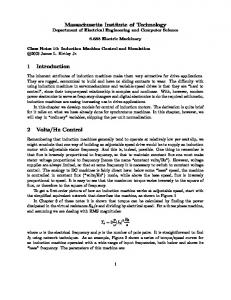
The following two figures show the wave form of the active and reactive power, stator and rotor. 10 00
Reactive Power
-1
Qr Qs
5 00 0 -5 00
-10 00
0
50 0
100 0 Time (ms)
150 0
200 0
Figure 11. Power reactive stator and rotor
Modeling and Control of a DFIG for Wind Turbine-Generator Systems (Mouna Lamnadi)
983
ISSN: 2088-8694
200
Voltages Vs
Voltages Vs and Currents IS
The following figure shows the wave forms of the voltages and stator currents.
Vs
100 0 -100
200
VsA
100
VsB
0
VsC
-100 -200
Is
0
-200 0
50 0
100 0 150 0 Time (ms)
50
1 50
2 00
200 0
(a)
(b) 150
Is
100
Currents Is
1 00 Time (ms)
Is
50
Is
0
A B C
-50 -100 -150
0
50
1 00
1 50
2 00
Time (ms)
(c) Figure 12. (a) Stator voltage and current in the plan “abc” (b) Zoom stator voltage in the plan "abc", (c) Zoom stator current in the plan "abc".
One can notice that the stator voltage is equal to that of the grid, while the currents obtained are sinusoidal, which implies a clean energy without harmonics supplied or drawn by the DFIG. The current and stator voltage are in phase opposition, this means that the stator active power is supplied from the generator to the grid. Tthe results obtained for this application, where the following observations can be distinguished: a. The specific speed l and the power coefficient Cp does not change a lot of values, they are almost equal to their optimal values references 9 and 0.4999 successively; b. The wind power captured follows its optimal reference and has the same shape as the wind profile applied, this rate is also consistent with the wind torque side of the DFIG; c. The speed of the DFIG is the image of wind causing the wind, it properly follows its reference; d. The shapes of the electromagnetic torque of the DFIG and its reference, are virtually identical, but different from the shape of the profile of the wind speed due to the dynamic torque due to inertia; e. The phase shift between the voltage 180° and the stator current phase reflects a production of active power only to the stator as illustrated in figure powers; f. The shape of the components of the stator flux orientation shows a good flow to ensure vector control well decoupled from the DFIG.
4.
CONCLUSION The object of this work consists in modeling, control and simulation of a wind system operating at random wind (speed).The application of vector control orientation of the flow rotor gives a simple stabilization of the wind system. The results show that the proposal of the rotor flux orientation control system to DFIG of variable speed can be considered as an interesting solution in field of wind energy. In this respect , this work can be continued and completed by the implementation of this command in a DSP card. IJPEDS Vol. 7, No. 3, September 2016 : 973 – 985
IJPEDS 5.
ISSN: 2088-8694
984
ANNEXE
Table 1. Parametres of wind power system Parameters of the turbine Diameter of blade R=35.25 m Gain multiplier G=16 Inertia of the turbine J=0.3125 Kg.m2 Coefficient of viscosity f=0.00673 m.s-1 Parameters of the DFIG stator resistance Rs=0.455 rotor resistance Rr=0.62 stator inductance Ls=0.084H rotor inductance Lr=0.081H Mutual inductance Msr=0.078H Number of poles P=2
REFERENCES [1] [2] [3] [4] [5] [6] [7] [8]
[9]
[10]
[11]
[12] [13]
[14]
[15]
[16]
[17]
[18]
Lei Y, Mullane A, Lightbody G, Yacamini R,Modeling of the wind turbine with a doubly-fed induction generator for grid integration studies, IEEE Trans,Energy Conversion, vol. 21, no. 1, pp. 257-264, Mar. 2006. Kingdom of Morocco National Office of Electricity and Potable Water”, http://www.one.org.ma/ Minister of Energy, Mining, Water and the Environment (Morocco), “Minister of Energy, Mining, Water and the Environment (Morocco)”. T.Ackermann and Soder, L. “An Overview of Wind Energy-Status 2002”. Renewable and Sustainable Energy Reviews, 6(1-2), 67-127 (2002). T. Burton, D. Sharpe, N. Jenkins and E. Bossanyi, “Wind Energy Handbook.”John Wiley&Sons, Ltd, 2001. B. Hopfensperger, D.J. Atkinson, and R. Lakin, “Statorflux-oriented control of a doubly-fed induction machine with and without position encoder”, IEE Proc.-Electr. Power Applications, vol. 147, no. 4, July 2000, pp. 241- 250. Y. Zhou, P. Bauer, J.A. Ferreira, and J. Pierik, “Control of DFIG Under Unsymmetrical Voltage Dip”, IEEE Power Electronics Specialists Conference, 2007, pp. 933-938. D.V.N. Ananth et V.N. Kumar, “Flux Based Sensorless Speed Sensing and Real and Reactive Power Flow Control with Look-up Table based Maximum Power Point Tracking Technique for Grid Connected Doubly Fed Induction Generator”, Indonesian Journal of Electrical Engineering and Informatics (IJEEI), vol. 3, no 4, 2015. A. Boulahia, M. Adel, et H. Benalla, “Predictive Power Control of Grid and Rotor Side converters in Doubly Fed Induction Generators Based Wind Turbine”, Bulletin of Electrical Engineering and Informatics, vol. 2, no 4, p. 258–264, 2013. B.Bossoufi, M.Karim, A.Lagrioui, M.Taoussi, M.L.EL Hafyani, “Backstepping control of DFIG Generators for Wide-Range Variable-Speed Wind Turbines”, IJAAC International Journal of Automation and Control , pp 122140, Vol.8 No.2, July 2014. Badre Bossoufi, Mohammed Karim, Ahmed Lagrioui, Mohammed Taoussi, Aziz Derouich, “Observer backstepping control of DFIG-Generators for wind turbines variable-speed: FPGA-based implementation”, Renewable Energy, 81 (2015) 903e917. A. Davigny, Participation aux services système de fermes éoliennes à vitesse variable intégrant un stockage inertiel d’énergie, Thèse de Doctorat, USTL Lille (France), 2007. Bossoufi, B., Karim, M. Ionita, S., Lagrioui, A. “The Optimal Direct Torque Control of a PMSM drive: FPGABased Implementation with Matlab & Simulink Simulation”, Journal of Theoretical and Applied Information Technology JATIT, Vol. 28 No. 2, pp 63-72, 30 June 2011. Bossoufi, B., Karim, M. Ionita, S., Lagrioui, A. “DTC CONTROL BASED ARTIFICIAL NEURAL NETWORK FOR HIGH PERFORMANCE PMSM DRIVE”, Journal of Theoretical and Applied Information Technology JATIT, Vol. 33 No. 2, pp 165-176, 30 November 2011. Bossoufi, B., Karim, M. Ionita, S., Lagrioui, A. “Nonlinear Non Adaptive Backstepping with Sliding-Mode Torque Control Approach for PMSM Motor”, Journal of Journal of Electrical Systems JES, Vol. 8 No. 2, pp 236-248, June 2012. B.Bossoufi, M.Karim, A.Lagrioui, M.Taoussi, M.L.EL Hafyani “Backstepping control of DFIG Generators for Wide-Range Variable-Speed Wind Turbines”, IJAAC International Journal of Automation and Control, pp 122140, Vol. 8 No. 2, July 2014. B.Bossoufi, M.Karim, S.Ionita, A.Lagrioui, “Performance Analysis of Direct Torque Control (DTC) for Synchronous Machine Permanent Magnet (PMSM)”, 2010 IEEE 16th International Symposium for Design and Technology of Electronics Packages, IEEE-SIITME’2010, art. No. 5649125, pp. 237-242. Pitesti, Romania. Badre Bossoufi1, Hala Alami Aroussi1, ElMostafa Ziani1, Ahmed Lagrioui2, Aziz Derouich3 “Low Speed Sensorless Control of DFIG Generators Drive for Wind Turbines System”.
Modeling and Control of a DFIG for Wind Turbine-Generator Systems (Mouna Lamnadi)
985
ISSN: 2088-8694
[19] Bossoufi, B., Karim, M. Ionita, S., Lagrioui, A., (2012b) “Low-Speed Sensorless Control of PMSM Motor drive Using a NONLINEAR Approach BACKSTEPPING Control: FPGA-Based Implementation”, Journal of Theoretical and Applied Information Technology JATIT, 29 February, Vol. 36 No. 1, pp 154-166. [20] X. Yu, K. Strunz, “Combined long-term and shortterm access storage for sustainable energy system”, 2004 IEEE Power Engineering Society General Meeting, vol. 2, pp. 1946-1951, 10 June 2004.
IJPEDS Vol. 7, No. 3, September 2016 : 973 – 985