Elazzaoui, J Electr Electron Syst 2015, 4:1 http://dx.doi.org/10.4172/2332-0796.1000141
Electrical & Electronic Systems Research Article Research Article
OpenAccess Access Open
Modeling and Control of a Wind System Based Doubly Fed Induction Generator: Optimization of the Power Produced Marouan Elazzaoui* Department of Electrical Engineering, Electronic Power and Control Laboratory, Mohammedia School of Engineering Université Mohammed V-Agdal, Morocco
Abstract This paper deals with the modeling and control of a wind energy system based on a doubly-fed induction generator. Initially, an MPPT control strategy of the doubly-fed induction generator is presented. Thereafter, the control vectororiented stator flux is performed. Finally, the simulation results of the wind system using a doubly-fed of 3 MW are presented in the Matlab / Simulink environment.
Keywords: Wind turbine; Doubly-fed induction generator; Converter; Vector control
Introduction Today, wind energy has become a viable solution for energy production, in addition to other renewable energy sources. While the majority of wind turbines are fixed speed, the number of variable speed wind turbines is increasing [1]. The doubly-fed induction generator with vector control is a machine that has excellent performance and is commonly used in the wind turbine industry [2]. There are many reasons for using a doubly-fed induction generator for a variable speed wind turbine; such as reducing efforts on the mechanical parts, reducing noise and the possibility of control of active and reactive power [3]. The wind system using DFIG and a “back-to-back” converter that connects the rotor of the generator and the network has many advantages (Figure 1). One advantage of this structure is that the power converters used are dimensioned to pass a fraction of the total power of the system [4,5]. Thereby reducing losses in power electronic components. The performance and power production does not only depend on the DFIG, but also the way in which the two parts of “back-to-back” converter is controlled. The power converter machine side is called «Rotor Side Converter» (RSC) and the grid side power converter is called «Grid Side Converter» (GSC). The machine side power converter controls the active power and reactive power produced by the machine. As for the grid-side converter, it controls the DC bus voltage and line-side power factor. In this paper, we present a technique for controlling the two power converters. We will analyze their dynamic performance by simulations in Matlab / Simulink environment. We start with a model of the wind turbine,then a technique for continued operation at maximum power point tracking (MPPT) will be presented.
Subsequently, we present a model of DFIG in the landmark Park, and the general principle of the control of two power converters. We conclude by presenting the simulation results and their interpretation.
Modeling of Wind Turbine By applying the theory of momentum and Bernoulli’s theorem, we can determine the incident power (the theoretical power) due to wind [6,7]: 1
Pincident = .ρ .S .v 2 2
(1)
S : the surface swept by the blades of the turbine m
2
ρ : the density of air ( ρ = 1, 225kg / m 2 at atmospheric pressure). 1 v : wind speed ( Tsa = C p ( λ , β ) ρ Sv3 m/s) 2Ωt In a wind energy system, due to various losses, the power extracted from provided on the rotor of the turbine is less than the incident power. The power extracted is expressed by [8]:
1 Pextract = .ρ .S .C p ( λ , β ) .v3 2
(2)
Cp (λ,β) is called the power coefficient, which expresses the aerodynamic efficiency of the turbine. It depends on the ratio, which is the ratio between the speed at the end of the blades and the wind speed, and the orientation angle β of the blades. The ratio λ can be expressed by the following equation (8,9):
λ=
Ωt . R v
(3)
Ω: The turbine speed of rotation (rad/s). R: The length of a blade. The maximum of power coefficient Cp was determined by Albert
*Corresponding author: Marouan Elazzaoui, Department of Electrical Engineering, Electronic Power and Control Laboratory, Mohammedia School of Engineering Université Mohammed V-Agdal, Morocco, E-mail:
[email protected] Received January 15, 2015; Accepted March 03, 2015; Published April 04, 2015 Citation: Elazzaoui M (2015) Modeling and Control of a Wind System Based Doubly Fed Induction Generator: Optimization of the Power Produced. J Electr Electron Syst 4: 141. doi:10.4172/2332-0796.10001141
Figure 1: Structure of a wind energy system based on DFIG.
J Electr Electron Syst ISSN: 2332-0796 JEES an open access journal
Copyright: © 2015 Elazzaoui M. This is an open-access article distributed under the terms of the Creative Commons Attribution License, which permits unrestricted use, distribution, and reproduction in any medium, provided the original author and source are credited.
Volume 4 • Issue 1 • 1000141
Citation: Elazzaoui M (2015) Modeling and Control of a Wind System Based Doubly Fed Induction Generator: Optimization of the Power Produced. J Electr Electron Syst 4: 141. doi:10.4172/2332-0796.10001141
Page 2 of 8 Betz as follows:
16 ) = 0,5926 C p _ max (λ , β= 27
(4)
The power coefficient is intrinsic to the formation of wind turbine and depends on the profiles of the blades. The power coefficient can be modeled with a single equation that depends on the speed ratio λ and the orientation angle β of the blades as follows: π (λ + 0.1) C p _ max (λ , β ) = ( 0.5 − 0.0167.( β − 2) ) sin − 0.00184.(λ − 3)( β − 2) 18.5 − 0.3( β − 2)
(5)
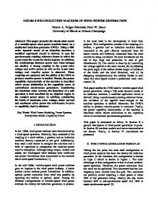
adjustable speed to ensure optimal operating point of power extraction. In this context, the ratio of the speed of wind λ must be maintained at its optimum value λ=λopt on a certain wind speed range. Thus, the power coefficient would be maintained at its maximum value (Figure 4).
Modelling of DFIG The electrical equations of DFIG in the dq reference can be written equation 9,11:
The Figure 2 shows curves of the power coefficient as a function of λ for various β values. This gives a maximum power coefficient of 0.5 for a speed ratio λ which is 9.13 maintaining β at 2°. By setting β and λ respectively to their optimal values, the wind system will provide optimum electrical power. The aerodynamic torque on the slow axis is expressed by: Tsa =
1 C p ( λ , β ) ρ Sv3 2Ωt
(6)
Mechanical speed is related to the speed of rotation of the turbine by the coefficient of the gearbox. The torque on the slow axis is connected to the torque on the fast axis (generator side) by the coefficient of the gearbox (Figure 3). The total inertia J is made up of the inertia of the turbine plotted on the generator rotor and inertia of the generator:
Jt = J + Jg G2
Figure 2: Power coefficient as a function of λ for various β values.
(7)
M Ps = −vsq L irq s M .vsq Q = vsq 2 − ird s Ls
J t : inertia of the turbine.
J g : inertia of the generator. To determine the evolution of the mechanical speed from total torque Tmec applied to the rotor of DFIG, we apply the fundamental equation of dynamics:
J=
d Ωm = Tmec = T fa − Tem − f Ω m dt
Figure 3: Block diagram of the turbine model.
(8)
Ω: mechanical speed of DFIG.
Tfa : aerodynamic torque on the fast axis of the turbine. Tem: Electromagnetic torque. fΩm : coefficient of friction. The previous equations used to establish the block diagram of the turbine model.
Maximum Power Extraction In order to capture the maximum power of the incident wind, permanently must adjust the rotational speed of the turbine to the wind. An erroneous speed measurement therefore inevitably leads to degradation of the received power that is why most wind turbines are controlled without control of the speed. The controller in this case should impose a reference torque to allow DFIG turning at an
J Electr Electron Syst ISSN: 2332-0796 JEES an open access journal
Figure 4: Block diagram without control of the speed.
Volume 4 • Issue 1 • 1000141
Citation: Elazzaoui M (2015) Modeling and Control of a Wind System Based Doubly Fed Induction Generator: Optimization of the Power Produced. J Electr Electron Syst 4: 141. doi:10.4172/2332-0796.10001141
Page 3 of 8
vsd vsq v rd vrq
dϕ sd − ωsϕ sq dt dϕ = Rs isq + sq − ωsϕ sd dt dϕ rd = Rr ird + − ωrϕ rq dt dϕ = Rr irq + rq − ωrϕ rd dt = Rs isd +
(9)
Stator flux
(10)
The equations for the flux in dq reference are given by:
ϕ sd = = ϕ sq ϕrd = = ϕ rq
Ls isq + Mirq Lr irq + Misq
With:
Ls = ls − M s , Lr = lr − M r : Cyclic inductances of stator and rotor phase. ls et lr inductors own stator and rotor of the machine. Ms et Mr mutual inductances between two stator phases and between two rotor phases of the machine. M: maximum mutual inductance between stator and rotor stage. p: number of pairs of poles of the DFIG. The expression of the electromagnetic torque of the DFIG based on the flow and stator currents is written as follows: (12)
The active and reactive power of the stator and rotor are written as follows (9,11):
(13)
Vector Control of DFIG
In the field of production of wind energy, these are average machines and high power which are mainly used. Thus, we neglect the stator resistance. Taking the constant stator flux we can write: (16)
• The maximum extraction control wind power by controlling said MPPT (detailed in Section III). • Control of RSC by controlling the electromagnetic torque and stator reactive power of DFIG. • Control of GSC by controlling the voltage of the DC bus and the active and reactive power exchanged with the grid.
Control of the rotor side converter (RSC) The principle of the Control of the rotor side converter is shown in Figure 8. The Controls of electromagnetic torque and stator reactive power will be obtained by controlling the rotor dq axes currents of DFIG. From the equations (15) and (16) we obtain the expression of the stator current:
vsq M = − ird isd ω L Ls s s i = − M i rq sq LS
• Flow control in closed loop, where the frequency and voltage are considered variables (unstable grid). • Flow control in open loop when the voltage and frequency are constant (stable grid).
σ = 1−
In our study, the frequency and voltage are assumed to be constant. We can see from equation (12), the strong coupling between flows
(17)
These expressions are then substituted in the equation (11) of the rotor flux which then become:
Mvsq = ϕrd σ Lr ird + ωs Ls ϕ = σ L i r rq rq
DFIG control strategies are based on two different approaches (12):
J Electr Electron Syst ISSN: 2332-0796 JEES an open access journal
(15)
ϕ sd = Ls isd + Mird = ϕ s ϕ sq = Ls isq + Mirq = 0
To determine the angles necessary for transformation Park of the stator variables θs and the rotor variables θr, we used a phase locked loop (PLL) as shown in Figure 6. This PLL allows to accurately estimate the frequency and amplitude of the grid (13). The architecture of the controller is shown in Figure 7. It is based on the three-phase model of the electromechanical conversion chain of the wind energy system. From Figure 7, three commands are needed:
Lr isd + Misd
= Ps vsd isd + vsq isq = Qs vsq isd + vsd isq = Pr vrd ird + vsq irq = Qs vrq ird + vrd irq
(14)
vsd = 0 ωsϕ s vsq= V= s
Ls isd + Mird
= Tem p (ϕ sd isd − ϕ sq isd )
ϕ s is oriented along the axis. Thus, we can write:
ϕ sd = ϕ s ϕ sq = 0
The pulse of the stator currents being constant, the rotor pulse is derived by:
ω r = ω s − pΩ m
and currents. Indeed, the electromagnetic torque is the cross product between flows and stator currents, making the control of DFIG particularly difficult. To simplify ordering, we approximate the model to that of the DC machine which has the advantage of having a natural coupling between flows and currents. For this, we apply vector control, also known order by direction of flow. We choose dq reference linked to the rotating field (Figure 5).
With:
(18)
M2 Lr Ls : the dispersion coefficient of the DFIG Substituting the
expressions of the direct and quadrature components of the rotor flux in the equation (9) we get:
Volume 4 • Issue 1 • 1000141
Citation: Elazzaoui M (2015) Modeling and Control of a Wind System Based Doubly Fed Induction Generator: Optimization of the Power Produced. J Electr Electron Syst 4: 141. doi:10.4172/2332-0796.10001141
Page 4 of 8 di Rr ird + σ Lr rd + erd vrd = dt v = R i + σ L dird + e + e φ r rq r rq rq dt
With:
ωr MVsq −σ Lrωr irq ; erq = erd = σ Lrωr ird ; eφ = ωs Ls
The expression of the electromagnetic torque becomes:
Tem = −
pMvsq
ωs Ls
(20)
irq
Stator active and reactive powers are expressed by: Figure 5: Orientation of the axis d to stator flux.
M Ps = −vsq L irq s M .vsq Q = vsq 2 − ird s Ls
(21)
These last expressions show that the choice of coordinate system (dq) makes the electromagnetic torque produced by the DFIG, and therefore the stator power, proportional to the current of the rotor axis (q). The stator reactive power, in turn, is proportional to the current of the rotor axis (d) due to a constant imposed by the grid. Thus, these stator powers can be controlled independently of one another. This shows us that we can set up a control rotor currents due to the influence of the couplings, every current can be controlled independently each with its own controller. The reference values for these regulators will be the rotor axis current (q) and the rotor axis current (d). The block diagram of the control loops of the axis rotor currents (dq) is shown in Figure 9, the regulators used are PI correctors. The rotor current of the reference axis (q) is derived from the MPPT control via the electromagnetic torque reference (Figure 4). The rotor current of the reference axis (d) is, in turn, derived from the control of the stator reactive power. From the equations (20) and (21) we obtain: Figure 6: Establishment angles processing using a PLL.
Figure 7: Control architecture of the wind system.
J Electr Electron Syst ISSN: 2332-0796 JEES an open access journal
v L − s Qs* + sq ird * = M .vsq ωs M
(22)
Figure 8: Principle of the Control of the rotor side converter (RSC).
Volume 4 • Issue 1 • 1000141
Citation: Elazzaoui M (2015) Modeling and Control of a Wind System Based Doubly Fed Induction Generator: Optimization of the Power Produced. J Electr Electron Syst 4: 141. doi:10.4172/2332-0796.10001141
Page 5 of 8
ird * = −
ωs Ls
pMvsq
(23)
Tem*
Figure 10 shows the block diagram of the control of RSC. Figure 11 show the principle of the Control of the rotor side converter performs the following two functions: •
Control currents flowing in the RL filter.
•
Control voltage of the DC bus.
Control currents flowing in the RL filter According to Kirchhoff’s laws, the equations of the filter in the three-phase reference voltages are given by: di − R f i f 1 − L f f 1 + Vs1 V f 1 = dt di f 2 v = − R i − L + Vs 2 f2 f f2 f dt di − R f i fa − L f fa + Vsa V fa = dt
Figure 10: Control of RSC.
(24)
Applying the Park transformation, we obtain: Pf *
− R f i fd − L f v fd = v = − R f i fq − L f fq
di fd dt di fq dt
+ e fd
(25)
− ω L f i fq + e fq
With:
e fd = ωs L f i fd ; e fq = −ωs L f i fd + vsq
Figure 11: Principle of the Control of the grid side converter (GSC).
The pattern of binding of GSC to grid in the landmark Park along the stator rotating field shows us that we can put in place a control of the currents flowing in the RL filter is given to the influence of the couplings, every axis can be controlled independently with each its own PI controller. The reference values for these controllers will be current in RL filter axes (dq) (Figure 12). The reference currents ifd * and ifq * are respectively the voltage from the control block of the DC bus and control of reactive power at the GSC connection point to the grid (Figure 11).
Figure 12: Control currents flowing in the RL filter.
Neglecting losses in the resistance of RL filter and taking the orientation of the coordinate system (dq) connected to the rotary stator field vsd=0 the equations for the powers generated by the GSC are given by:
Pf = vsq i fq Q f = vsq i fd Figure 9: Control of rotor currents.
J Electr Electron Syst ISSN: 2332-0796 JEES an open access journal
(26)
From these equations, it is possible to impose the active and reactive power reference noted here Pf* and Qf* imposing the following reference currents:
Volume 4 • Issue 1 • 1000141
Citation: Elazzaoui M (2015) Modeling and Control of a Wind System Based Doubly Fed Induction Generator: Optimization of the Power Produced. J Electr Electron Syst 4: 141. doi:10.4172/2332-0796.10001141
Page 6 of 8
* Qf * i fd = vsq * * Pf i = fq vsq
(27)
speed used for simulation, while Figure 16 shows the shaft rotational speed derived by the turbine. The figures (Figures 17 and 18) show that the electromagnetic torque and reactive power provided by DFIG follow their references, this is due to control of direct and quadrature components of the rotor current. Figure 19 illustrates the power stator
Control of the DC bus voltage We can express the powers involved on the DC bus by:
Pr ed = vdc ired Pc = vdc icond P = v i dc ond ond
(28)
These powers are linked by the relation:
Pr ed= Pc + Pond
(29) Neglecting all the Joule losses (losses in the capacitor, the converter and the RL filter), we can write:
P= Pr ed= Pc + Pond f
(30)
Figure 14: Control of GSC.
By adjusting the power Pf, then it is possible to control the power Pc in the capacitor and therefore to regulate the DC bus voltage. To do this, the Pond and powers must be known to determine Pf*. The reference power for the capacitor is connected to the reference current flowing through the capacitor:
Pc* = vdc icond *
(31)
Regulating the DC bus voltage is then effected by an external loop (with respect to the inner loop control of current), for maintaining a constant voltage on the DC bus, with a PI controller that generates the reference current ic* in the capacitor (Figure 13). Figure 14 shows the block diagram of the control of GSC. This block diagram includes the terms of decoupling and compensation to be able to independently control the (dq) axes currents circulating in the RL filter and the active and reactive power exchanged between the GSC and the grid.
Simulation Results
Figure 15: Wind speed.
The simulations of the whole system were performed with Matlab/ Simulink, the DC bus reference voltage, denoted Vdc* is set at 1200 V. The reactive power references Qs* and Qf* are set to 0 VAr, ensuring unity power factor. We present in this section the results of the proposed control. Figure 15 illustrates the profile of the average wind
Figure 13: Control loop of the DC bus voltage.
J Electr Electron Syst ISSN: 2332-0796 JEES an open access journal
Figure 16: Mechanical speed.
Volume 4 • Issue 1 • 1000141
Citation: Elazzaoui M (2015) Modeling and Control of a Wind System Based Doubly Fed Induction Generator: Optimization of the Power Produced. J Electr Electron Syst 4: 141. doi:10.4172/2332-0796.10001141
Page 7 of 8
Figure 17: Electromagnetic torque (reference and simulated). Figure 20: DC bus voltage.
Figure 21: Stator current evolution.
Conclusion Figure 18: Stator reactive power (reference and simulated).
This paper is devoted to modeling, simulation and analysis of a wind turbine operating at variable speed. Stable operation of the wind energy system was obtained with the application of the control direction of the flow. The overall operation of the wind turbine and its control system were illustrated in transient and permanent regimes. DFIG operates in two quadrants. Operation hyposynchronous for positive slip and hypersynchronous operation for a negative slippage. The generator supplied power to the grid with an active power regardless of the mode of operation. The control strategy based on the PI control with correction was tested. Simulation results show that the proposed wind energy system is feasible and has many benefits. References 1. Ackermann T (2002), An Overview of Wind Energy-Status 2002, Renewable and Sustainable Energy Reviews 6: 67-127. 2. http://www.gepower.com/prod_serv/products/wind_trubines/en/index.html 3. Burton T, Sharpe D, Jenkins N (2001) Wind Energy Handbook, John Wiley&Sons, Ltd.
Figure 19: Stator active power.
extracted, and Figure 20 shows that the DC bus voltage is perfectly regulated. We see in Figure 21 that the current delivered by the wind system is in phase with respect to the supply voltage, this confirms that the wind system injects the active power into the grid. J Electr Electron Syst ISSN: 2332-0796 JEES an open access journal
4. Kling WL, Slootweg JG (2002) Wind Turbines as Power Plants, Oslo, Norway: in Proceeding of the IEEE/Cigré workshop on Wind Power and the impacts on Power Systems. 5. Xu L, Wei C (1995) Torque and Reactive Power Control of a Doubly Fed Induction Machine by Position Sensorless Scheme. IEEE Trans, Industry Application. 6. Alesina A, Venturini M (1988) Intrinsic Amplitude Limits and Optimum Design of 9 Switches Direct PWM AC-AC converter, Proc. of PESC, 1284-1290.
Volume 4 • Issue 1 • 1000141
Citation: Elazzaoui M (2015) Modeling and Control of a Wind System Based Doubly Fed Induction Generator: Optimization of the Power Produced. J Electr Electron Syst 4: 141. doi:10.4172/2332-0796.10001141
Page 8 of 8 7. Seyoum D, Grantham C (2003) Terminal Voltage Control of a Wind Turbine Driven Isolated Induction Generator using Stator Oriented Field Control, IEEE Transactions on Industry Applications, 846-852.
8. Davigany A (2007) «Participation aux services système de fermes éoliennes à vitesse variable integrant un stockage inertiel d’énergie,» Thèse de Doctorat, USTL Lille.
Submit your next manuscript and get advantages of OMICS Group submissions Unique features: • • •
User friendly/feasible website-translation of your paper to 50 world’s leading languages Audio Version of published paper Digital articles to share and explore
Special features:
Citation: Elazzaoui M (2015) Modeling and Control of a Wind System Based Doubly Fed Induction Generator: Optimization of the Power Produced. J Electr Electron Syst 4: 141. doi:10.4172/2332-0796.10001141
J Electr Electron Syst ISSN: 2332-0796 JEES an open access journal
• • • • • • • •
400 Open Access Journals 30,000 editorial team 21 days rapid review process Quality and quick editorial, review and publication processing Indexing at PubMed (partial), Scopus, EBSCO, Index Copernicus and Google Scholar etc Sharing Option: Social Networking Enabled Authors, Reviewers and Editors rewarded with online Scientific Credits Better discount for your subsequent articles
Submit your manuscript at: www.omicsonline.org/submission/
Volume 4 • Issue 1 • 1000141