Modeling and Control of Master-Slave Microgrid with Communication Delay Asma Alfergani
Ashraf Khalil
Electrical and Electronics Engineering Department University of Benghazi Benghazi, Libya
[email protected]
Electrical and Electronics Engineering Department University of Benghazi Benghazi, Libya
[email protected]
Abstract— Microgrids gathered a lot of attention in the last decade and are believed to be the future power systems. The renewable energy sources can be easily integrated into the Microgrid. Renewable energy sources such as PV, wind and fuel cells are usually connected through voltage-source inverters in the Microgrid. In order to share the same loads, these inverters are connected in parallel and to achieve the load sharing the control strategy is a must. In this paper, the master-slave control strategy in the dq frame is presented. The reference current signals are sent from the master to the slave converters. A model for master-slave communication-based Microgrid is presented and the system is modeled as a general time delay system. The maximum time delay that guarantees the stability of the system is calculated using a Lyapunov-Krasovskii based linear matrix inequalities method. The communication delay mimics the scenario when the wireless network or the Controller Area Network are used as a communication medium between the inverters. Keywords— communication network; delay; LMI; master/slave control strategy; Microgrid; Parallel inverters; Phased locked loop;
I.
INTRODUCTION
Increased energy demand, rising price of conventional energy sources, and the negative environmental impacts led to shift the focus to the use of the renewable and sustainable energy sources. Renewable or sustainable energy technologies such as photovoltaic panels, wind turbines, and fuel cells; have attracted widespread attention during the last decade. Most of the renewable energy sources are usually equipped with DC/AC inverters, which form a parallel inverters system in order to share the load, that can be connected to the grid. This configuration is known as Microgrid [1]. The unpredictable and intermittent nature of renewable energy sources has kept them from integrating with the utility grid. However, the concept of Microgrid has opened the scope to incorporate renewable energy sources into the conventional grid, without a direct coupling with the conventional grid components. This is possible due to the unique feature of the Microgrid, which allows both synchronized grid connected operation and islanded operation in case of instabilities or power outages in the main grid. Integrating many energy sources makes the control of Microgrids very challenging and an active research area.
For the Microgrid to achieve the load sharing and coordinate the control tasks between the inverters, it is necessary to apply a good and reliable control strategy. With the advances in network technology, a wireless network can be used for the control signals exchange. The use of the communication network for control purposes reduces the cost and the complexity of the system, however, the induced time delay has a strong effect on the system stability. The control strategies are divided into communication-based or communication-less. There are many reviews on the control strategies in inverter-based Microgrids. For more detailed surveys on the control strategies in parallel connected inverters the reader can refer to [2-3] and the references therein. The role of the controller in parallel inverters in the Microgrid is to have good current sharing while maintaining the system stability. Also, the controller must achieve synchronization, and to guarantee that the frequency and the voltage are within the permissible range. The control strategies based on communication include centralized, distributed and master-slave control strategies [2]. The control strategies without communication are generally based on the wellknown droop method. In the centralized control strategy, all the information is collected by the centralized controller and then the commands are issued back to the system. In this control strategy, all the inverters work as current sources and the voltage is controlled in the central controller. The current sharing is forced at all times even during the transient, and different power rating inverters can be connected without changing the control structure [2]. The main disadvantage of this strategy is the single point of failure and the need for sending the reference voltage to all the inverters in the network, which requires high bandwidth communication link and the system is sensitive to nonlinear loads [2]. In the distributed control strategy the rotational reference frame (dq0) is used instead of the stationary reference frame (abc). It can be used only in balanced systems. The voltage controller controls the output voltage by setting the average current demands [2]. In current/power sharing control method the average unit current can be determined by measuring the total load current and divide this current by the number of units in the system. There are excellent features of the current/power sharing, the load sharing is forced during transient and the circulating currents are reduced. In addition, a lower-bandwidth communication link is needed.
The decentralized control is used to solve the problems associated with the controllers interactions. The decentralized controller relies only on local information. This technique is usually used when the distance between parallel inverters is long, and it can be applied in islanded mode or grid-connected mode. One of the most widely used decentralized control is the Droop control [4]. The main idea is to regulate the voltage and the frequency by regulating the reactive and the active power respectively which can be sensed locally. The Droop control method has many desirable features such as expandability, modularity, redundancy, and flexibility. There are as well, some drawbacks such as slow transient response and possibility of circulating currents. As the interconnections are neglected the overall system stability is questionable. In the master-slave control strategy, one of the converters is known to be the master while the others are the slaves, the master controller contains the voltage controller while the slaves contain current controllers and have to track the master’s reference current [5]. In this control strategy, there is a transfer of information between the master controller and the slaves controllers. In order to reduce the complexity and the cost while increasing the reliability, the control signals are exchanged through shared networks. In this case, the system becomes what is known as a networked control system (NCS). Because it involves less information transfer the master-slave control strategy is preferable for NCS applications. Many researchers have reported the application of the master-slave control strategy over a communication network, but there are no studies on modeling the parallel inverters with the communication delay and how the delay could affect the stability of the system. In [6] the Controller Area Network (CAN) is used to exchange the control signals from the master to the slave. The signals which are sent the reference currents, id and iq and the synchronization signal, however, the authors do not point out how to guarantee the stability of the system in terms of the maximum time delay. In [7] the communication platform for a Microgrid implementing master-slave control strategy is proposed. The CAN-open protocol is used for the communication between the master and the slave. The automaster-slave control strategy is presented in [8]. The system is implemented practically and the power sharing is precise. The master distributes the real power and the reactive power signals among the slave converters. The CAN is used for both synchronization and the current sharing in [9]. The authors pointed out that there is a communication delay, but the controller does not take it into account. The impact of the communication delay and the data drop outs on the stability of parallel inverters is presented in [10]. The master-slave control strategy has been implemented over communication network, but the real power and the reactive power are used as the reference signals. These signals are then sent through the CAN to the slave converters in the network. The real power and the reactive power are correlated to the frequency and the voltage respectively. A small signal model is then developed and the stability with the time delay is analyzed using a stability criterion method on Lyapunov-Krasovskii functional. The performance of the system with the master-slave control
strategy with a communication network is better than the performance with the droop control strategy [11]. In this paper, a model for the Microgrid with master-slave control strategy over a communication network is presented. When the control loop is closed through a communication network time delay and data loss are unavoidable which can lead to system instability. In order to achieve system stability, a stability analysis with communication delay should be carried out where the reference signals are sent through a shared network. In the next sections, the mathematical model of parallel inverters based on the switching averaging is briefly described. Then a mathematical model of the inverter based Microgrid with communication delay is described. Also, the master-slave control strategy is explained. A LyapunovKrasovskii stability criterion is used to test the stability of the system with the presence of the communication delay. A simulation using Matlab/Simulink is carried out to test the control strategy operation with the presence of the time delay. II.
MODELING OF THE INVERTER BASED MICROGRID WITH COMMUNICATION DELAY
The typical circuit of two parallel three-phase voltage source inverters with different DC sources is shown in Fig.1.
Fig. 1.
A system of two parallel inverters
A. Mathematical model of parallel inverter The average model of the phase leg is derived based on the switching averaging. The two parallel inverters are shown in Fig. 2.
Fig. 2.
The two parallel inverters Microgrid [12]
After transformation of the variables in the stationary coordinates Xabc into the rotating coordinates Xdqz, the average model can be simplified [13, 14 and 15] based on iz=iz1=-iz2≈ 0:
d v d 1 id 1 id 2 1 / RC − ω v d ⋅ (1) = + − 1 / RC v q dt v q 2C iq1 iq 2 ω d id 1 1 d d 1 1 vd 0 − ω id 1 ⋅ (2) i = d Vdc1 − v − dt q1 L1 q1 L1 q ω 0 iq1 d id 2 1 d d 2 1 vd 0 − ω id 2 ⋅ (3) i = d Vdc 2 − v − dt q 2 L2 q 2 L2 q ω 0 iq 2 where C, L1, and L2 are the filter capacitor and inductor, ω is the radian frequency. id1, id2, iq1 and iq2 are the dq currents for the first and second inverter. vd and vq are the voltages in the dq reference frame. The Vdc1 and Vdc2 represent the renewable energy source such as the wind turbine or the PV array after they are converted to DC [16] [17]. Writing (1), (2) and (3) in general matrix form: (4) x& = Ax (t ) + Bu (t ) The state vector and the control vector are given as: x = [vd v q id 1 iq1 id 2 iq 2 ]T
u = [d d 1 d q1 d d 2 d q 2 ]T where d is the duty ratio, the matrices A, B can be obtained as: − 1 / RC −ω − 1 / L1 A= 0 − 1 / L2 0
0 0 B= 0 0
ω − 1 / RC 0 − 1 / L1 0 − 1 / L2
0 Vdc1 / L1
1 / 2C 0 1 / 2C 0 0 1 / 2C 0 1 / 2C 0 0 0 ω −ω 0 0 0 0 0 0 ω 0 0 −ω 0
0
0
0
0
Vdc1 / L1
0
0
0
0
Vdc 2 / L2
0
0
0
0
0 0 Vdc 2 / L2 0
iq - ref = K vqp (vq - ref - vq ) + K vqiφq
Fig. 3.
(5)
T
(6)
(8)
(10)
Control loops of two parallel inverters
The master current controller is given by: dγ 1 / dt = (id - ref - id 1 )
B. Master-Slave control strategy The master-slave control strategy is used where the first inverter has two control loops and the second inverter has only current control loop. The inner control loop of the master controller independently regulates the inverter output current in the rotating reference frame, id and iq. The outer loop of the master controller in the voltage control mode are used to produce the dq axis current references id-ref and iq-ref, then these control signals are sent through the communication network to the slave controller as shown in Fig. 3. A proportional- Integral (PI) control scheme is used in both the master and slave controllers, the master voltage controller is given as: dφd / dt = ( v d - ref - vd ) (7)
dφq / dt = (v q - ref - v q )
The master voltage controller generates the reference current as follows: id - ref = K vdp (vd - ref - vd ) + K vdiφd (9)
(11)
dγ 2 / dt = (iq - ref - iq1 ) Substituting (9) and (10) into (11) and (12), we get; dγ 1 / dt = ( K vdp (v d - ref - vd ) + K vdiφd - id 1 )
(13)
(12)
dγ 2 / dt = ( K vqp ( v q - ref - v q ) + K vqiφq - iq1 )
(14)
The slave controller is given as: dγ 3 / dt = (id - ref (t - τ ) - id 2 )
(15)
dγ 4 / dt = (iq - ref (t - τ ) - iq 2 )
(16)
Substituting (9) and (10) into (15) and (16), we get; dγ 3 / dt = ( K vdp (v d - ref - v d (t − τ )) + K vdiφd (t − τ ) - id 2 )
(17)
dγ 4 / dt = ( K vqp ( vq-ref - vq ( t - τ )) + K vqiφq ( t - τ ) - iq 2 )
(18)
The controller model is then given by: dφd / dt = ( v d - ref - vd )
(19)
dφq / dt = (v q - ref - v q )
(20)
dγ 1 / dt = ( K vdp ( v d - ref - v d ) + K vdiφd - id 1 )
(21)
dγ 2 / dt = ( K vqp ( v q - ref - v q ) + K vqiφq - iq1 )
(22)
dγ 3 / dt = ( K vdp (v d - ref - v d (t − τ )) + K vdiφd (t − τ ) - id 2 )
(23)
dγ 4 / dt = ( K vqp ( v q - ref - v q (t − τ )) + K vqiφq (t − τ ) - iq 2 ) Equations (19)-(24) can be written in matrix form as: z& = Ex(t ) + Fz (t ) + Ed x (t − τ ) + Fd z (t − τ ) where;
(24) (25)
K idp1 K vdi 0 D= 0 0
0 0 0 0 0 K idi 2 0 0 0 0 0 K iqi 2 Substituting (31) into (4) and writing the resulting equation in matrix form along with (25) we get; x& (t ) A + BC BD x ( t ) z&( t ) = E F z ( t ) (32) BC d BDd x ( t − τ ( t )) + Fd z (t − τ (t )) Ed
0 0 0 0 0 −1 Φ d 0 Φ −1 0 0 0 0 q − K vdp γ1 0 −1 0 0 0 z = ,E = − K vqp 0 − 1 0 0 γ2 0 0 γ3 0 0 0 −1 0 0 0 0 0 − 1 0 γ 4 0 0 0 0 0 0 0 0 0 0 0 0 0 0 0 0 0 0 Ed = 0 0 0 0 0 0 − K vdp 0 0 0 0 0 − K vqp 0 0 0 0 0 0 0 0 0 0 0 0 0 0 0 0 0 0 0 0 0 0 0 0 0 0 0 0 0 0 0 0 0 0 0 K vdi 0 0 0 0 0 F = Fd = 0 0 0 0 0 0 0 K vqi 0 0 0 0 Kvdi 0 0 0 0 0 0 0 0 0 0 0 0 0 0 0 0 0 0 Kvqi 0 0 0 0
A + BC A0 = E III.
(27)
+ K iqi 2γ 4
(28) (29)
Equations (26-29) can be written in matrix form as: u = u (t ) + u (t − τ )
u = Cx (t ) + C d x (t − τ ) + Dz (t ) + Dd z (t − τ ) where; 0 − K idp1 0 − K idp1 K vdp 0 − K iqp1 K vqp 0 − K iqp1 C= 0 0 0 0 0 0 0 0
0 0 0 0 Cd = - Kidp 2 K vdp 0 0 - Kiqp 2 K vqp 0 0 0 0 0 0 Dd = K idp 2 K vdi 0 0 K iqp 2 K vqi 0 0
0 0 0 0 0 0 0 0 0 0 0 0 0 0 0 0 0 0 0 0 0 0 0 0 0 0 0 0
(30) (31)
0 0 − K idp 2 0
0 0
(33)
where;
d q1 = ( K iqp1 )( K vqp (v q - ref - vq ) + K vqiφq - iq1 ) + K iqi1γ 2
d q 2 = K iqp 2 ( K vqp ( vq - ref - vq (t − τ )) + K vqiφq (t − τ ) - iq 2 )
0 K iqi1
x&cl (t ) = A0 x(t ) + Ad x(t - τ (t ))
(26)
+ K idi 2γ 3
K idi1 0
Equation (32) can be further written as:
The duty cycle equations are given as: d d 1 = ( K idp1 )( K vdp (vd - ref - vd ) + K vdiφd - id 1 ) + K idi1γ 1
d d 2 = K idp 2 ( K vdp (vd - ref - vd (t − τ )) + K vdiφd (t − τ ) - id 2 )
0 K iqp1 K vqi
0 − K iqp 2 0 0
BD BC Ad = d F Ed
BDd x (t ) x cl (t ) = Fd z (t )
STABILITY ANALYSIS WITH COMMUNICATION DELAY
The presence of the communication delay makes the Microgrid a time delay dependent control system. To guarantee the stability the maximum allowable delay bound (MADB) must be found [18]. Most the methods for calculating the MADB are based on using LyapunovKrasovskii functional and Razumikhin functional. The method used in this paper is based on Lyapunov-Krasovskii functional and replacing the delay term by Newton-Leibnitz formula. Then the stability problem is formulated as a set of LMIs. The Microgrid system in (33) with a time delay can be represented as:
x& (t ) = Ax(t ) + Ad x(t - τ (t )) t ≥ 0
(34)
x(t ) = Φ(t ) (35) t ∈ [ − ρ ,0 ] Where A and Ad are constant matrices with appropriate dimensions. Φ (t ) is the initial condition of the system for the time interval t ∈ [− ρ ,0] . The time-varying delay is τ(t) and satisfies the following: 0 ≤ τ (t ) ≤ ρ , τ&(t ) ≤ µ ≤ 1 (36) where ρ is the upper bound of the time delay, µ is the upper bound on the variable rate of the time delay. Theorem 1 [19]: Given scalars ρ > 0 and µ > 0 , the time-delay system (33) is asymptotically stable if there exist symmetric
positive-definite
matrices
P = PT > 0 ,
Q = Q T > 0 and Z = Z T > 0 , asymmetric semi-positive-
X 12 X definite matrix X = 11 ≥ 0 , and any appropriate T X X 22 12 dimensioned matrices Y and T such that the following LMIs are true:
Y T ≥ 0 Z
1
0 0
Fig. 5.
The 3-Φ currents, A
0
-100
0
0.02
0.04 0.06 Time (seconds)
0.08
0.1
0
0.02
0.04 0.06 Time (seconds)
0.08
0.1
The 3-Φ currents, A
100 50 0 -50 -100
Fig. 6.
The output currents of the first and second inverters
150
100
50
0
-50
-100
-150
0
The single phase current, A
150
-80
Fig. 4.
The output three-phase voltages
0.1
Fig. 8.
The output currents of the load The phase current of the first inverter The phase current of the second inverter
0
-60
0.08
0.1
-20 -40
0.04 0.06 Time, (seconds)
0.08
20
-150 -200
0.04 0.06 Time, (seconds)
40
-100
0.02
0.02
Fig. 7.
60
-50
0.1
-50
200
0
0.08
50
80
50
0.04 0.06 Time, (seconds)
100
250
100
0.02
The active and reactive power of first and second inverters
The 3-Φ load current, A
The sampling time, Ts of the system must be less than the MADB. Choosing the gain without considering the sampling time, may give some oscillation in the reactive power of the load. The controllers parameter of the parallel inverter-based Microgrid are as follows: the gains of the master voltage PI controller are Kvdp=5, Kvqp=5, Kvdi=400, and Kvqi=400, and the master current PI controller are Kidp1=1, Kidi1=100, Kiqp1=100, and Kiqi1=60. In addition, the gains of PI slave controller are Kidp2=1, Kidi2=100, Kiqp2=100, and Kiqi2=60. The binary iteration is used to calculate the maximum allowable delay bound [20] [21] [22]. The three-phase output voltages of the parallel inverters are shown in Fig. 4, which shows a stable operation of the system. The output power of the first and second inverters are shown in Fig. 5. As can be seen, the power of the second inverter accurately tracks the power of the first inverter. The output currents of the first inverter, the second inverter and the load current are shown in Fig. 6 and Fig. 7 respectively. The good current sharing is clear from Fig. 6. Since the two inverters are synchronized using the PLL, there is no phase difference between the phase current of the first and second inverter as shown in Fig. 8.
0
real power of the first inverter reactive power of the first inverter real power of the second inverter reactive power of the second inverter
1.5
RESULTS
To test the results a MATLAB/SIMULINK simulation has been carried out. The parallel inverters parameters are as follows: the capacitance and the inductance of the filters are 22 µF and 4 mH respectively. The load resistance R equals 4.25 Ohm. The frequency reference is set to be 50 Hz. The PLL (Phase Locked Loop) was used in this system to synchronize two parallel inverters since the two inverters give the same power to shared the load. Moreover, the gains of the master-slave controller must be tuned to get a stable system. Additionally, analysis the stability of the system with the delay based on the LMI is linked to the simulation results.
The 3-Φ voltage, V
The The The The
0.5
Φ 22 = −T − T T − (1 − µ )Q + ρX 22
-250
4
2
Φ 12 = PAd - Y + T T + ρX 12 IV.
x 10
2.5
The Power, W
Φ 11 Φ 12 ρAT Z X 11 X 12 T T T Φ = Φ 12 Φ 22 ρAd Z < 0 Ψ = X 12 X 22 T ρZA ρZA Y − ρZ TT d where; Φ 11 = PA + AT P + Y + Y T + Q + ρX 11
0
0.02
0.04 0.06 Time, (seconds)
0.08
0.1
Syncronised phase currents of first and second inverters
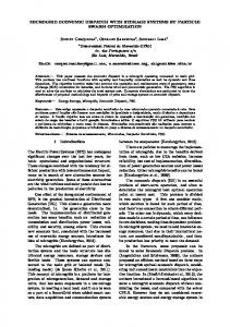
The reference currents are sent from the first inverter to the second. the id1 , iq1 , id2 and iq2 are shown in Fig .9. when the currents are transformed from the abc to dqz there will be oscillations in id and iq because of the harmonics from the 50 Hz so a low-pass filter is used to remove the harmonics.
[6]
[7]
60 Id1
Iq1
Iz1
Id2
Iq2
Iz2
50
[8]
The dqz currents, A
40 30
[9]
20 10 0
[10]
-10 -20
0
Fig. 9.
0.02
0.04 0.06 Time (seconds)
0.08
0.1
The dqz current of first and second inverters
V.
[11]
CONCLUSION
In this paper, the stability of parallel inverters controlled over the network is investigated. The parallel inverters implement master/slave control strategy where the master sends the reference signal to the slave inverter through a shared network. The mathematical model of the inverter based Microgrid with communication delay has been derived and used to estimate the MADB. The stability criterion is formulated as LMI which is solved using Matlab. The controller gains are used as the controller parameter. The controller is tested using the nonlinear models in Matlab SimPowerSystem/Toolbox. In addition, the PLL is used to synchronize two parallel inverters. The master-slave control strategy with communication delay shows good performance and precise power sharing.
[12]
[13]
[14]
[15]
[16]
[17]
REFERENCES [18] [1]
[2]
[3]
[4]
[5]
B. Lasseter, “Microgrids [distributed power generation],” in 2001 IEEE Power Engineering Society Winter Meeting. Conference Proceedings, Columbus, OH, 2001, pp. 146-149 vol.1. M. Prodanovic, T. C. Green, and H. Mansir, “Survey of control methods for three-phase inverters in parallel connection,” 2000 Eighth International Conference on Power Electronics and Variable Speed Drives (IEE Conf. Publ. No. 475), London, 2000, pp. 472-477. P.Monica and M.Kowsalya, "Control strategies of parallel operated inverters in renewable energy application: A review," Renewable and Sustainable Energy Reviews, vol. 65, 2016, pp. 885–901. K. De Brabandere, B. Bolsens, J. Van den Keybus, A. Woyte, J. Driesen, R. Belmans and K. U. Leuven, "A voltage and frequency droop control method for parallel inverters," In 2004 IEEE 35th Annual Power Electronics Specialists Conference, 2004, pp. 2501-2507. S. K. Mazumder, M. Tahir, and K. Acharya, “Master-Slave currentsharing control of a parallel DC-DC converter system over an RF communication interface,” in IEEE Transactions on Industrial Electronics, vol. 55, (1), pp. 59-66, Jan. 2008.
[19]
[20]
[21]
[22]
W. Yongqing, Z. Xiaofeng, Q. Mingzhong, and K. Jun, "Control of parallel inverters based on CAN bus in large-capacity motor drive," in the 2008 Third IEEE Internation Conference on Electric Unity Deregulation Restructuring and Power Technologies, Piscataw, 2008, pp. 1375-1379. Y. Zhu, F. Zhuo and L. Xiong, "Communication Platform for Energy Management System in a Master-slave Control Structure Microgrid," in Proceedings of The 7th International Power Electronics and Motion Control Conference, Harbin, China, 2012, pp. 141-145. Y. Pei, G. Jiang, X. Yang and Z. Wang, "Auto-Master-Slave Control Technique of Par allel Inverters in Distributed AC Power Systems and UPS," in 2004 IEEE 35rd Annuul Power EIecrronics Specialisrs Conference, Aachen, Germany, 2004, pp. 2050-2053. Z. Chunjiang, C. Guitao, G. Zhongnan and W. Weiyang, "An Alternating-master-salve Parallel Control Research for Single Phase Paralleled Inverters Based on CAN Bus," in 2006. CES/IEEE 5th International Power Electronics and Motion Control Conference, 2006. IPEMC, Shanghai, 2006, pp. 1-5. Y. Zhang, H. Ma and Xiaorui Wang, "Impact of Varying Time-Delays and Data Dropouts on Networked Control System for Inverter Parallel Operation," in IECON 2011 - 37th Annual Conference of the IEEE Industrial Electronics Society, Melbourne, 2011, pp. 2590 - 2594. Y. Zhang, H. Ma, G. Zhao and J. Guo, "A Current-Sharing Method Based on Networked Control for Three-Phase Parallel Inverter," in IECON 2012 - 38th Annual Conference on IEEE Industrial Electronics Society, Montreal, 2012, pp. 57-61. A. Khalil, K. A. Alfaitori and A. Elbarsha, "Stability Analysis of Parallel-Inverters in Microgrid," 2014 20th International Conference on Automation and Computing, ICAC 2014, Cranfield, 2014, pp. 110-115. Z. Ye, “Modeling and Control of Parallel Three-Phase PWM Converters,” Ph.D. thesis, Virginia State University, September 15, 2000. Y. Zhang, “Small-Signal Modeling and Analysis of Parallel- Connected Power Converter Systems for Distributed Energy Resources,” Ph.D. thesis, University of Miami, 2011. Y. Zhang, Z. Jiang, and X. Yu, “Small-Signal Modeling and Analysis of Parallel-Connected Voltage Source Inverters,” In the proceedings of the IEEE 6th confenerence on Power Electronic and Motion Control, pp. 377-383, May 17-20, 2009. A. Khalil, K. A. Alfaitori, A. Asheibi, "Modeling and Control of PV/Wind Microgrid," 2016 7th International Renewable Energy Congress (IREC), Hammamet, 2016, pp. 1-6. A. Khalil, K. Ateea, "Modeling and Control of Photovoltaic-Based Microgrid," International Journal of Renewable Energy Research, vol. 3, no. 5, pp. 826- 835, 2015. A. F. Khalil and W. Jihong, “A New Method for Estimating the Maximum Allowable Delay in Networked Control of bounded nonlinear systems,” The 17th International Conference on Automation and Computing, Huddersfield, 2011, pp. 80-85. M. Wu, Yong, Y. He and J.-H. She, Stability Analysis and Robust Control of Time-Delay System, Heidelberg: Springer-Verlag Berlin and Heidelberg GmbH & Co. K, 2010. A. Khalil, S. Elkawafi, A. I. Elgaiya, J. Wang, "Delay-Dependent Stability of DC Microgrid with Time-Varying Delay," 2016 22nd International Conference on Automation and Computing (ICAC), Colchester, 2016, pp. 360-365. S. Elkawafi, A. Khalil, A. I. Elgaiyar and J. Wang, "Delay-dependent stability of LFC in Microgrid with varying time delays," 2016 22nd International Conference on Automation and Computing (ICAC), Colchester, 2016, pp. 354-359. A. Khalil, A. Ashiebi, J. Wang, "Stability of parallel DC/DC converters with time varying delay," 2016 IEEE International Conference on Power System Technology (POWERCON), Wollongong, NSW, 2016, pp. 1-6.