Proceedings of PAC09, Vancouver, BC, Canada
TU4RAC03
MODELING AND DESIGN OF HIGH-POWER INDUCTIVE OUTPUT TUBES E. L. Wright and K. T. Nguyen Beam Wave Research, Inc., 5406 Bradley Blvd., Bethesda, MD 20814
[email protected] J. A. Pasour, S. J. Cooke and B. Levush Code 6840, Naval Research Laboratory Washington D.C., 20375 J. J. Petillo and I. A. Chernyavskiy SAIC, 700 Technology Park Dr. Billerica, MA 01821 J. F. DeFord and B. L. Held Simulation Technology and Applied Research, Inc. Mequon, WI 53092 Abstract The accelerator community is making the transition to inductive output tube (IOT) technology for a number of high-power UHF and L-band applications as a result of their inherent benefits. Scientists, funded by the Office of Naval Research and Naval Research Laboratory, are investigating the physics of the beam-wave interaction of the IOT. The time-domain electrostatic PIC code MICHELLE [1], in conjunction with the Analyst® [2] suite of electromagnetic codes, were used to model the cathode-grid-anode structure that comprises the input cavity. Our investigation has led to the discovery of a delay mechanism responsible for intra-bunch charge formation, as evidenced by IOT X-ray generation with energies significantly higher than the cathode accelerating potential, increasing with RF output power. Time-domain PIC results of this effect will be shown. We will also present simulation results of the large-signal beam wave interaction in the output cavity using the code TESLA [3, 4]. Examples of single beam and multiple-beam (MB) IOTs will also be discussed.
INTRODUCTION The IOT is a linear beam amplifier that is ideally suited to high-power operation at UHF [5] and L-band [6] frequencies. The IOT RF gridded electron gun directly bunches the beam resulting in a highly efficient, compact device. A key feature of the IOT is its linear transfer characteristics at the maximum efficiency point – users can maximize operating efficiency while maintaining a level of back-off to provide amplitude modulation headroom for accelerator beam control systems. These appealing features have resulted in a number of laboratories around the world making the transition to IOT technology for their next-generation machines [7-9]. The lack of availability of end-to-end modeling and simulation tools has limited the designers’ ability to develop high-level intuition that can lead to novel performance-improving designs. Historically development has been a lengthy and expensive cut-and-try endeavor for
tube manufacturers. Product improvement has been a slow evolutionary process, hampered by yield-impacting issues manufacturers still experience today. The majority of the yield-reducing problems are associated with the least understood area of the IOT: the electron optics of the input cavity and the time varying nature of the emission process. A greater understanding of the dynamics behind electron beam formation is needed to improve the yield and performance of IOTs. Although conceptually simple, the design and optimization of an IOT is quite difficult. The input cavity is extremely complex due to the intrinsically threedimensional topology. Two factors greatly complicate the modeling and optimization of the RF gridded gun of the input circuit: • Disparate spatial scales (~1000 to 1) of the electrodes and accelerating gap compared to the extremely fine grid and cathode-grid gap. • Difficulty of accurately modeling beam emission at low voltages, which occur at the beginning and end of each RF extraction cycle (beam head and tail effects). Our choice of conformal mesh finite-element methods forms the basis of the selection of codes for this approach. Our solution solves two problems; not only can conformal meshes resolve all the geometric detail (surface and volumetric), but our solution uses methods that are not constrained by the Courant condition. The need for extremely fine mesh resolution in the emitter-to-grid region has been confirmed to be beyond the scope of tractability of finite-difference methods and requires finite-element methods with conformal meshing capability. Under development are a suite of computationally efficient finite-element modeling and simulation tools to provide end-to-end simulation of IOTs. The primary codes are MICHELLE, a 3D time-domain PIC code, Analyst®, a 3D electromagnetic simulation suite, and TESLA, a 2.5D large signal code for modeling cavitytype linear beam amplifiers. These physics-based design
Radio Frequency Systems T08 - RF Power Sources
767
TU4RAC03
Proceedings of PAC09, Vancouver, BC, Canada
tools have been applied with great success by the vacuum electronics industry to develop an assortment of new and improved devices. Our goal is to achieve that same level of success for the case of the IOT and eventually the MBIOT.
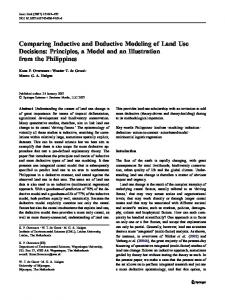
2) Output Cavity TESLA & Analyst
results of one simulated input power level can be seen in Figure 2. Some extremely interesting physics are observed. Note that there is current that is not immediately captured by the static field setup in the grid to anode gap – instead these particles move radially inward, towards the centerline of the geometry. This charge eventually makes
3) Collector MICHELLE & Analyst
1) Input Cavity / Electron Gun MICHELLE and Analyst
Figure 1: Three regions and codes used to model an IOT.
PRELIMIARY RESULTS Input Cavity/ Electron Gun Our starting point was to benchmark the codes as they exist today to determine their current capability of performing end-to-end modeling and simulation of a single beam IOT. To perform this task the IOT was broken up into three sections: 1) input cavity/ electron gun, 2) output cavity and 3) collector, Figure 1. As expected our effort focused primarily on the input cavity/ electron gun section of the simulation, although a study of the output cavity and collector simulation capabilities was also performed. To simplify the simulation a 12-fold axissymmetric electrostatic model of the input cavity/ electron gun was created. Initial simulation started with an analysis of the mesh density requirements on the cathode and grid surfaces and its affect on steady-state emission current. Finite element maximum edge lengths on the cathode and grid surfaces, and the volume between, were explored. Finite element edge lengths were varied from 100 microns down to 40 microns on these surfaces. We found that the quiescent current for a given set of electrode voltages was changing with mesh size – attempts to reduce the mesh below 40 microns were not possible due to the 32-bit limitation of the Analyst® mesher. A 64-bit version of the mesh generator is currently under development and will be used once it becomes available. The next step in the analysis was to simulate the timedomain behavior of the emission process using MICHELLE. The RF fields that drive the emission are modeled using the Analyst®-OM3p eigensolver, then imported into MICHELLE for the time-domain simulation. The RF field amplitudes were imported onto an identical grid and scaled to simulate the effect of changing the input power to the device. Time-domain
Figure 2: Time domain snapshots showing the evolution of anti-bunch current. its way out of the cathode to grid gap and is accelerated by the grid to anode fields; however the transit delay places the current between bunches. Current between bunches, referred to as anti-bunch current, will traverse the output cavity gap when the gap fields are phased for maximum acceleration and the particles will pick up energy as they move into the collector. This effect Radio Frequency Systems
768
T08 - RF Power Sources
Proceedings of PAC09, Vancouver, BC, Canada
explains how IOTs can create X-rays with energies much higher than the operating voltage, as evidenced by measurements on a number of high-power IOTs, even though they may be biased for Class-C operation. Up until now the transit delay mechanism responsible for the formation of anti-bunch current has been a mystery.
15
Emitter Current
Anode Current
Current (A)
12.5 10 7.5
simulation of MB-IOTs. Our simulation has been of a sector of a single-beam IOT geometry – an MB-IOT will have at least one full cathode/grid structure in the simulation space, and hence will require significantly more computational resources. A number of improvements are planned: • Improved meshing capabilities – mesh exclusion and mesh interpolation. • Develop an electron beam loading model. • Develop advanced emission models. This effort will lead to a greater understanding of IOTs and other density modulated devices, allowing designers to gain the insight and intuition necessary for improved device performance.
5
ACKNOWLEDGEMENT
2.5 0 0.00
1.43
2.86
4.29
5.71
Time (ns)
Figure 3: MICHELLE time-domain current density profiles.
Output Cavity Time-domain anode current was tracked as it crossed a predefined surface in the drift tunnel for use in TESLA. A sample MICHELLE current density profile, with 3.4 A of average emitter current and 2.7 A average anode current at 40 kV and frequency of 700 MHz, can be seen in Figure 3. This is but one of a series of current density profiles used for an output cavity gap optimization study, Figure 4, which shows how the output power varies as a function of gap resistance, the product of RSQ and QL at resonance, for several beam currents (input power levels). 120 Output Power (kW)
TU4RAC03
66%
100 80
68%
60 Io= 2.71
40
Io= 3.14
20
Io= 3.63
0 8000
10000
12000
14000
16000
Gap Resistance (Ohms)
Figure 4: TESLA output gap optimization.
FUTURE EFFORT Our focus moving forward will be to improve the various code modules in order to allow the modeling and
This work is supported by the U.S. Office of Naval Research and Naval Sea Systems Command. We would also like to thank our colleagues at CPI/MPP, in particular Mr. Tom Grant and Mr. Michael Cusick, for providing data and technical assistance.
REFERENCES [1] J.J. Petillo, et al., “Recent developments in the MICHELLE 2D/3D electron gun and collector modeling code”, IEEE Trans. Electron Devices Sci., vol. 52, no. 5, May 2005, pp. 742-748. [2] The Analyst Code, http://www.staarinc.com. [3] S.J. Cooke, K.T. Nguyen, A.N. Vlasov, T.M Antonsen Jr., B. Levush, T.A. Hargreaves, T.A.; M.F. Kirshner, “Validation of the large-signal klystron simulation code TESLA”, IEEE Transactions on Plasma Science, Volume 32, Issue 3, Part 1, June 2004, pp. 1136 – 1146. [4] I. A. Chernyavskiy, et al., “Parallel Simulation of Independent Beam Tunnels in Multiple Beam Klystrons Using TESLA”, IEEE Trans. Plasma Sci. , vol. 36, No 3, pp. 670-681, June 2008. [5] D.H. Preist, M.B. Shrader, “The klystrode - An unusual transmitting tube with potential for UHFTV”, IEEE Proceedings, vol. 70, Issue 11, November 1982, pp. 1318-1325. [6] H.P. Bohlen, “L-Band inductive output tubes”, 2003 4th IEEE International Conference on Vacuum Electronics, 28-30 May 2003, pp. 24-25. [7] N. Akoaka, et al., “Development of a proton accelerator for the JAERI Neutron Science Project”, Proceedings of the 1999 Particle Accelerator Conference, Vol. 5, 27 March – 2 April 1999, pp. 3546-3548. [8] M. Jensen, et al., “First results of the IOT based 300 kW 500 MHz amplifier for the Diamond Light Source”, Proceedings of the 2005 Particle Accelerator Conference, 16-20 May 2005, pp. 1883-1885. [9] A. Fabris, et al., “Installation and commissioning of the new 150 kW plant for the Elettra RF system upgrade”, Particle Accelerator Conference, PAC IEEE, 25-29 June 2007, pp. 2080-2082.
Radio Frequency Systems T08 - RF Power Sources
769