May 1, 1978 - Evaluation of Nonlinear. Satellite Links-A Volterra. Series Approach. S. BENEDETTO, Member, IEEE. E. BIGLIERI, Member, IEEE. R. DAFFARA.
Modeling and Performance Evaluation of Nonlinear Satellite Links-A Volterra Series Approach
S. BENEDETTO, Member, IEEE E. BIGLIERI, Member, IEEE
R. DAFFARA Istituto di Elettronica Politecnico, Italy
e
Telecomunicazioni
Abstract An analytical solution to the problem of modeling bandpass nonlinear channels and evaluating the performance of digital communication systems operating on them is presented. A method based on a Volterra series representation of the overall channel is first proposed, which allows one to extend to nonlinearities with memory the well-known concepts of complex envelope of bandpass signals and low-pass equivalent of bandpass linear systems. The general results previously mentioned are then applied to digital satellite communication systems operating over nonlinear channels. The effect of a nonlinear amplifier located in the satellite is considered, in combination with that of transmitting and receiving filters located in the Earth stations. In addition, both uplink and downlink noise are taken into account. Basic advantages of this approach are the generality it offers to the analysis and the fact that it allows accurate evaluation of the error probability in a short computer time.
Manuscript received May
1,
1978; revised November 8, 1978.
This work was supported by the European Space Agency under Contract 2328/74/HP. Authors'
address: Istituto di Elettronica e Telecomunicazioni
Politecnico, Corso Duca d. Abruzzi 24, Torino, Italy. 0018-9251/79/0700-0494 $00.75
494
1979 IEEE
1. Introduction Digital satellite communication systems are frequently operated over nonlinear channels with memory. In fact, most satellite repeaters are equipped with amplifiers working at or near saturation for better efficiency. In addition, for an efficient use of the frequency, only a restricted bandwidth is available, which causes each transmitted symbol to be affected by the previous symbol pattern. To analyze properly a communication situation like this, we must be able to combine the effects of the nonlinear amplifier located in the satellite with those of transmitting and receiving filters located in the Earth stations. Typically, an RF amplifier operated in a nonlinear region exhibits two kinds of nonlinearities. The first one relates the output power to the input power (this behavior is often referred to as AM/AM conversion) and the second one relates the output phase shift to the input power (AM/PM conversion) [1]. In addition, the reduced bandwidth assigned to the filters causes them to introduce intersymbol interference. A channel model taking into account these combined effects is clearly unwieldy; hence it is not surprising that no complete analytical treatment of the problem has yet been obtained. Several different efforts have been directed towards computing the performance of a nonlinear satellite link. The research in this field has followed two main tracks, the first one aimed at obtaining results from a complete model through simulation [2-5] and the second one simplifying the model in order to make feasible an analytical approach [6-7]. The basic advantage of the simulation approach lies in its generality, which allows one to analyze the effects on system performance of several impairments. However, simulation suffers from being rather time consuming, which often prevents extensive analyses or comparisons. Moreover, considerable care must often be taken in the choice of parameters related to random quantities. As an example, assume that the inclusion of uplink noise is done by adding a pseudorandom noise sequence at the input of the nonlinearity. If the downlink noise power is very small, the error performance of the system is dominated by the uplink noise. Hence, we are in a situation in which rare errors occur, being due to a random process generated by simulation. Clearly, a huge number of computer runs is needed in order to properly analyze a situation like this. Analytic approaches typically deal with a simplified model in which either the transmitting or the receiving filter is missing [6-7]. However, both of them must be taken into account for a proper analysis. In particular, the effect of transmitting filter is to introduce a certain amount of intersymbol interference, and hence of envelope fluctuations, in the signal entering the nonlinear device. The receiving
IEEE TRANSACTIONS ON AEROSPACE AND ELECTRONIC SYSTEMS
VOL. AES-15, NO.4
JULY 1979
IPUTPUT DATA
modulato
OTU
f(.h-t)
h-(t)
SDD
OUTPU
V2(t)
V1 (t)
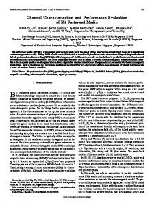
Fig. 1. Equivalent block diagram of digital satellite communication link.
filter itself introduces some more intersymbol interference, because its bandwidth must be small enough to cope with thermal noise. Other approaches combine analytical and numerical methods [8-91 or exploit a different criterion, such as mean-square error, to optimize the system [10]. Several investigators have calculated the performance of a phase-shift keyed (PSK) system through a purely amplitude-limiting channel [11-14]. Finally, in [15] a maximum-likelihood sequence estimator is derived for a binary PSK signal embedded in a nonlinear environ-
x (t) =
I"
exp(ja) 6(t - n 7)
(2.1)
where T` is the signaling rate and (aJ,)"_. is a stationary sequence of independent random variables (RV) taking on an even number M of equally likely values (2i + 1)rr/M, i =0, 1, ..., (M- 1). The signal i(t) enters a linear filter whose low-pass equivalent version has an impulse response h'(t). This filter takes into account the effects of the cascade of pulse-shaping filter, transmitting filter, and on-board input demultiplexing filter. For simplicity's sake, this ment. filter will be referred to hereafter as the transmitting The goal of this paper is to present an analytical treatment of the problem just described. The method filter. The output of the transmitting filter is first added proposed here is based on a Volterra series representation of the overall channel, including uplink noise and to a colored Gaussian noise v,(t) modeling the uplink the effects of filters before and after the nonlinearity. noise, then sent to a bandpass nonlinear device whose The basic advantage of this approach is the generality input-output relationship is described by a complex function f(.) as follows [16]: it offers to the analysis, and an important achievement is that accurate evaluation of the performance parameters is allowed in a short computer time. It is W (t) f(IZ"" (t) 1) explj arg [Z"" Qffi. (2.2) believed that this technique will offer a valuable tool for the analysis and design of digital communication systems operating over nonlinear channels. The linear filter h"(t) takes into account the onThe outline of the paper is as follows. The system board output multiplexing filter and the Earth-station model is described in Section II. In Section III the theory of Volterra series is briefly reviewed and band- receiving filter. It will be denoted as the receiving pass Volterra series are introduced in order to provide filter. After the addition of a Gaussian process v2(t) a representation for the complex envelope of the representing downlink noise, the output is finally sent signal at the channel output. In Section IV this theory to a sampler followed by a decision device (SDD) that is applied to the problem of modeling a nonlinear outputs an estimate of the transmitted symbol sesatellite channel and in Section V it is shown how the quence (a,,). Decisions are made by partitioning the error probability can be computed in this situation. complex plane into M congruent regions and The insertion of uplink noise is considered in Section associating an estimate to every received sample VI and some numerical examples are presented in Sec- according to which region the sample is falling into. The decision regions usually depend upon the phase tion VII. offset introduced by the bandpass nonlinear device, so that they may not be the same as for PSK transmitted on a linear channel. ^1
=
11. System Model
Our system model is based on an M-ary coherent PSK satellite channel, as shown in Fig. 1. The complex envelope of the PSK modulator output is
Ill. Volterra-Series Representation of Channel Volterra series provide an input-output relation-
BENEDETTO, ET AL.: EVALUATION OF NONLINEAR SATELLITE LINKS-A VOLTERRA SERIES APPROACH
495
ship for nonlinear channels with memory satisfying certain regularity conditions. Such a relationship takes the form
factors exp[±1jw,(t- Tr)] and such that the numbers of exponentials with a plus sign and a minus sign differ exactly by 1. The number of these products is (2k+1) and after a y(t) = X,1 10. dT, ... Jf0,dT, h,(T,, ..., Ti) little thought it is not difficult to see that all of them give the same values for the corresponding (2k + 1) (3.1) fold integral. Here the hypothesis that the Volterra .nfl,X(t Tr) kernels are symmetrical makes its appearance. where x(t) and y(t) are the input and the output of the Denoting now as y(t) the bandpass signal obtained channel, respectively. The functions h,( ... ), 1 l < at the channel output after retaining only its first-zone 00, that generalize the impulse response of linear component, we can write systems, completely describe the channel behavior. Thus the problem of characterizing a nonlinear system y(t) e -jWI O [(2k+ )/22k+11 with memory is equivalent to the problem of computing these functions, usually referred to as Volterra ...f ". dT2k+l *f dTlf
x(t) = .(t) exp(-jcwot)
[2x(t) exp(jcot) + x"*(t) exp(-jcoot).
k
nfk+lx
*
T,) e ijoTr
(t
T)
el/woTs
e+Jwt k [(2k+ )/22k+1
+
Jo0 *f
* fl
dT2*f
dT,f0 f
*h2k+l (T1,
...,
X*(t
-
J
odT2k+,
T2k+l) Tr) e+i woT
*n 2k+2 X(t - Ts) eiwoT,.
(3.4)
Compare now (3.3) and (3.4). It is immediately apparent that the complex envelope of y(t) is given by
k7=O[(2k- )/22k]
=
*J
(3.3)
Substitute now the last expression in (3.3) for x(t) in (3.1). Every product in the right-hand side of (3.1) will give rise to a sum of 2' products, each one involving l factors like
*
..., T2k+1)
(t
n,
y (t)
x(t) = ½/2 [x(t) + x*(t)] = 1/2
*h2k+l (Tl,
(3.2)
where co0 is the center frequency of x(t). Since x(t) is the real part of x(t), we can write
Joo0dT2
_c
kernels. In the following we shall assume that the Volterra kernels we are dealing with are symmetric functions of their arguments, i.e., any permutation of the arguments does not change the function values. This symmetry assumption does not entail any loss of generality [17]. We shall now derive a form of Volterra series which is suitable to represent bandpass channels like the one modeled in Section II. In particular, we want to derive a form of (3.1) in which the complex envelopes of input and output signals appear. Consider a real bandpass signal x(t) and the analytic signal associated with it, say x(t). Letting the symbol rv denote complex envelopes, we have
*
*-2k
h2k+1(Td,
*n l2k+l
X
dT2k++
..., T2k+ l)
*(t
-
T,) eJ,oT,
X(t - T) ejwCoTs.
(3.5)
exp[±jcoo(t- Tr)I.
Equation (3.5) relates input and output complex envelopes, as required. Anyway, to exploit in full the Since we are dealing with bandpass systems, we can complex envelope representations we can take a assume that only the first-zone spectral components of further step by defining low-pass equivalent Volterra the output signal are of interest, i.e., those not lying kernels. this To let us recall the hypothesis purpose, near the center frequency w0 are filtered out and that the channel is This means that the bandpass. hence will be neglected. Incidentally, this is the Fourier transforms of its Volterra kernels, i.e., assumption that allows us to model the on-board as in In nonlinearity (2.2). conclusion, among the products just described we shall retain only those exH2k+1 ((Vl, (02, ..., CO2k+1) = d-_ o 0J _o dT2k+l f hibiting an exponential factor exp(±jco0t) and * h2k+l (Tl, ..., T2k+l) exp[-j(w,l T, + (02 T2 disregard those with exponential factors exp(±jswot), s an integer not equal to 1. To do this, we consider + ... + (02k+l T2k+1)I only the products with an odd number, say 2k + 1, of (3.6) ...
496
IEEE TRANSACTIONS ON AEROSPACE AND ELECTRONIC SYSTEMS
VOL. AES-15, NO.4
JULY 1979
differ significantly from zero only over a narrow range of arguments around (±co0, ±co0, ..., ±wo). This concept, which is well known for ordinary transfer functions, can be justified by considering a sinusoidal signal with frequency w' and amplitude A as an input. The system output is, from (3.5), 111
y (1)
=
57mk=O(
2k+ 1 k
'
..., CL), k + --"
-C, ..., -co). k
0, ..., 0). Take now the inverse Fourier transform of these functions. Since the following property of multiple Fourier integrals holds:
2O2k+ 1
±
Tk
-
1/2 exp[-jc.oo(rT1 + T2 + .. ½
Tk+
-
_,,dC2k+l
F(CO
CL)o) expU(cw1
±
T1 +
CO0, CO2 (1)2
T2
±
kk+I(Ti.
...
9
T2k+1))
*-
T2k+l)
(3.9)
(3.7) and call h2k+,(...), 0 < k < oo, the "low-pass equi-
Due to the bandpass hypothesis, we do expect that y(t) is significantly nonzero only for cw' zcOw, which is obtained if H2,+, (...) behaves as mentioned before. Since H2k+l (...) is significantly nonzero only in the neighborhood of 22k+" points of the (2k + 1)th dimensional space, we can think of H2k+,(...) as a sum of 22k+1 "baseband" functions with arguments (wj ± cO, (C2 ± COo, ..., CO2k+1 ± WO). Each one of them is significantly nonzero only in the neighborhood of (0,
... f
T2k+l)
...,
+
) A 2k+ 1 '4
dwt),
h2k+l(TL,
l\1
H2k+l (Cl, C(),
f,_oo
Denoting this term by h2k+l(...), we can approximate
h2k+1(. ...)-as far as the output y(t) is concerned -as
w0,
+
valent Volterra kernels." With this definition, goal is finally achieved by writing
C(t)
=
27k
[(2+
.fJ
m
n 2k+l
2kf+1dO f_
dT2k+1h2k+l(Ti, X
~s--k+1 x"'(t
-
...,
our
.
T2.+1)
nl
x
(t
-
Tr)
(3.10)
T,,).
It is seen that (3.10), which does not seem to have been observed previously, gives an input-output relationship for a bandpass nonlinear system with memory in terms of the complex envelopes of the input and output signals. The channel is completely characterized by its low-pass equivalent Volterra kernels, a generalization of low-pass equivalent impulse response to nonlinear channels. IV. Application to Satellite Links
+
C2k+1 T2k+1)I
=
exp{-jCWo(±-Ti ±T2 .. t,,+i)} f dX0
we see that h2k+l(...) can be expressed as a sum of 22k+1 baseband kernels, each one being multiplied by a factor like
Let us now return to our initial problem, which involves the channel model represented in Fig. 1. The channel portion that we want to model using the bandpass Volterra series theory developed in the previous section is represented in Fig. 2. For the moment we shall exclude the noise v1(t) from consideration. Assume that the function g(.) characterizing the nonlinearity can be expanded in a power series:
exp[-jCWO(±Ti, ±T2, ..., ±T2k+1)I.
g(s) = Xk=l Yk Sk
f _oo0 da2k+l
galI
** *9 .
C2k+l)
.exp[(alT + *-T+ a2k+1 T2k+1)]
(3.8)
Under our narrowband approximation, we can neglect in the expression of h2k+l(...) all the terms which cause the appearance of factors exp(±jncOt), n # 0, in the integrals (3.5). In fact, these integrals vary much more rapidly than those with n = 0, so that the values of the corresponding integrals are relatively small. There is only one term in which no rapidly varying exponentials appear, viz., the one corresponding to the baseband component of H2k+l(...) whose arguments are (CO, + ()o ,CL)2 + (1)o .
.
O2k+1
-
. . .,
l)o).
(O)k +(C)o, (A)k+l
(A)o,
(4.1)
(
With this assumption we can write
y(t)
=
hdT(T) g[f10 h'(u - T) x(t -u)du] f dT= *
n
t
*
J. Tkhk(T1,
-0
...,
Tk)
(4.2)
-Tr)
where the following definition has been made
hi(T1,
...,
TI) AA Ylf "o. h-m ni 1 h'(T, r--
T) dT.
(4.3)
It is easily seen that (4.2) has the form of a Volterra series, whose kernels are given by (4.3). We want now to transform (4.2) into a similar one involving only complex envelopes of input and output
BENEDETTO, ET AL.: EVALUATION OF NONLINEAR SATELLITE LINKS-A VOLTERRA SERIES APPROACH
497
kl
*
VFl(t)
ff*(-,r--1if C)o) nf2k+l ~~s-k+l -
* If(C,
as
Fig. 2. Nonlinearity with memory including uplink noise.
it can be easily seen by computing the transform. Thus, using (3.9), we finally get
h2k+l(Tl, T2,
....
T2k+l)
nfl h* (Tr
9(0 Shifter
Fig. 3. In-phase and quadrature representation of device exhibiting AM/AM and AM/PM effects.
a nonlinear
signals, as well as low-pass equivalent Volterra kernels derived from (4.3). To do this, we take first the Fourier transform of (4.3), which gives, for = 2k + 1 H2k+1(C1,
2k+i)
= Y2k+1
IJ(c1 +
(4.7)
Co)o)
h+(T)
=
T)
_
nk+ h'(T.
T) dT
where h'(.), h"(.) are the low-pass equivalent impulse responses of the filters. It may be interesting to observe that, if HM(.) and H(.) are symmetric around the center frequency coo, then the impulse responses h'(.) and h"(.) turn out to be real and the integral in (4.8) is real too. We turn now our attention to the memoryless nonlinear device of Fig. 2. In order to characterize it, let us observe that the bandpass Volterra series expansion for it can be obtained by taking h'(.) = h"(.) = d(.) in (4.8). Using (3.10) and identifying (see Fig. 2) x(t) and y(t) with z(t) and w(t), respectively, we get w(t)
=
.,o j[y2k+l(
)/22k+1] [Z*(t)Ik [z(t)]
(4.9)
W2k+1)
+
(4.8)
Thus we can characterize a bandpass memoryless nonlinear device if we are able to figure out the y appearing in the input-output relationship (4.9). It must where If(s) and H'(.) are now the transfer functions be observed that the model just taken for the of the two filters represented in Fig. 2. Introducing nonlinearity does not allow a possible AM/PM conthe low-pass equivalent transfer functions M(.) and version effect to be taken into account. H'(.) according to the decomposition If AM/PM conversion takes place, as it happens with traveling-wave tube (TWT) amplifiers, the model I(7) If(M Wo) If O) of the nonlinearity must be modified as shown in Fig. 3. A combination of two in-phase and quadrature I'(co) = I'(cl Wo)+ f*( o-coO) (4.5) nonlinearities, each one exhibiting AM/AM conversion effects only, can take AM/PM into account [18]. we can evaluate the low-pass equivalent Volterra It is easy to see that with this assumption (4.9) still kernels. In fact, substituting (4.5) into (4.4), we get holds true, provided that the coefficients y, are defined as *
2k+l:( l
+
-
=
H2k+1(m01
(4.4)
r)
**
D2k+1)
=
*(
Y2k+1
[(w1 +*±-
+ W2k+1
IY
y4
o) +
If
(.- C
X
(-)2
(- 2k+1
()
;+
(4.10)
jy;'
where V' and V' are the coefficients of the power series (4.6) expansions of g'(.) and g"(.), respectively. Similarly, with definition (4.10) the Volterra Expanding the products in the right-hand side of kernels still retain the form (4.8). (4.6), we get a sum of 22k+1 terms. Only one of them In conclusion, the Volterra kernels for our satellite gives rise to the factor channel can be derived by computing integral (4.8) once the low-pass equivalent impulse responses of the exp[-jCWo(T1 + *.* + Tk Tk+1 T2k+1)] two filters h'(.) and h"(.) and the complex coefficients
+n l{If(W,r tCo) +
(
cor,
co)}*
-*
after the inverse Fourier transform, viz., y2k+1[HI (W1
498
+
W2
+ **
+
CO2k+1
WO)]
Y2k+l are known.
Before closing this section, we shall give expressions that relate the coefficients Y2k+1 to some common representations of the nonlinear device. The usual way
IEEE TRANSACTIONS ON AEROSPACE AND ELECTRONIC SYSTEMS
VOL. AES-15, NO.4
JULY 1979
to represent the nonlinearity is to give the complex function f(.), whose action is shown in (2.2).1 To do this, take z(t) = Q(t) exp j1(t) and rewrite
(4.9) as
y2k+ [(2k )/22k+1] Q2k+l(t)
w(t) = ej
ro
=
r(t.)
Then, inserting (4.12) into (2.2) and comparing with (4.1 1), we get
(4.13)
Y2k+1 = (22k+l/(2kl)] d*.
Similarly, assume that the function fl(.) has been expanded in the form ATQ) = X1,=b, J,(6,aQ)
(4.14)
where a is a real constant, b1, ..., bL are complex numbers, and the 6, can take the value 6, = 1 [16] or are the first zeros of the Bessel function J,(.) [7]. Recalling the Taylor series expansion of J,(.), .l.Lb,d6,
(4.15)
.
V. Performance Evaluation
exp(jao) k=o[( -
+ I,IIck *
(4.12)
AIQ) = Ik=odk Qk.
=
k
)/22k+1I
.H2k+1 (0, 0, ..., 0) + 1/2 1.,, exp(ia.,) H,(n,)
(4.11)
Now, suppose that the function fl(.) is given in the form of a power series with complex coefficients
Y2k+1 = C2k
After sampling this signal at time instant t = to, we have
2k+ 1
-
1)/22_+1] E
expU(aCln
E'2k+l
+ afl2 +... + Qr k+,a1 lk+2
-a,2k+)] H2k+1 (n,, ..., n2k+l) + vO where n,, n2, ..., n2k+l v2(to) and
H2*+n l,
... ,
n2n+l)
(5.3)
O, O, ..., 0 and where vO _
h2k+i(to - ni T, ..., to
-
n2k+lT). (5.4)
Hereafter the complex numbers H2,+,( ..) will be referred to as the Volterra coefficients of the system. In the right-hand side of (5.3), one can easily recognize the various contributions to the received signal: useful signal, intersymbol interference produced by linear distortion, contribution of the nonlinearity to intersymbol interference, noise. The choice of the first term in (5.3) as the useful signal has been made because it is the only term in which the "useful symbol" exp(ia0) appears as a factor of a deterministic quantity. Let us now proceed to evaluate the error probability. Due to the symmetry of the problem, the error probability does not depend on the symbol actually transmitted. Thus, assuming that the phase i/M has been sent, we get
In this section we shall apply the general results obtained before to the analysis of satellite communication links using CPSK modulation. As a first step toward the solution of this problem, suppose that the uplink noise is negligible as compared with the downlink noise. This restrictive PM(e) = 1 -PE