International Journal of Power Electronics and Drive System (IJPEDS) Vol. 3, No. 2, June 2013, pp. 185~192 ISSN: 2088-8694
185
Modeling and Simulation of a Solar Photovoltaic System, Its Dynamics and Transient Characteristics in LABVIEW M. Abdulkadir, A. S. Samosir, A. H. M. Yatim Department of Energy Conversion, Faculty of Electrical Engineering, Universiti Teknologi Malaysia 81310 Skudai, Johor Bahru, Malaysia
Article Info
ABSTRACT
Article history:
This paper proposes a LABVIEW simulator for photovoltaic (PV) systems. The effect of irradiance and temperature on PV module is very crucial when computing the model PV parameters. Many modeling techniques were used but this approach enables the computation of model parameters at any irradiance and temperature point. It has the ability to simultaneously compute all the PV model parameters. The accuracy of the simulator is verified by applying the model to 36 W PV modules. The performance of the model is tested using a single diode model, a shunt resistance Rp and series resistance Rs. The proposed model was found to be better and accurate for any irradiance and temperature variations. The proposed model can be very useful for PV Engineers and expert who require a simple, fast and accurate PV simulator to design their systems.
Received Feb 9, 2013 Revised May 5 20, 2013 Accepted May 16, 2013 Keyword: LABVIEW Photovoltaic
Copyright © 2013 Institute of Advanced Engineering and Science. All rights reserved.
Corresponding Author: M. Abdulkadir Department of Energy Conversion, Faculty of Electrical Engineering, Universiti Teknologi Malaysia, 81310, Skudai, Johor Bahru, Malaysia. Email:
[email protected]
1.
INTRODUCTION With the world economic development and growing demand for energy, the conventional energy sources have become increasingly unable to meet the world demand for the energy. Thus, it is important to explore more and better means of alternative energy sources like sunlight, wind and biomass. Photovoltaic energy is a source of interesting energy; it is renewable, inexhaustible and non-polluting, and it is more and more intensively used as energy sources in various applications [1]. In regard to endless importance of solar energy, it is worth saying that solar energy is a unique perspective solution for energy crisis. Meanwhile, despite all these advantages of solar energy, they do not present desirable efficiency [2], [3]. Renewable energy is gaining tremendous attention in both academia and industry in an effort to reduce greenhouse emissions. The main renewable sources are biomass, geothermal, hydro, photovoltaic, and wind. Photovoltaic (PV) power is expected to have the fastest annual growth rate having already shown a top growth rate of more than 50% in 2006 and 2007 [4]. PV power systems have the advantage that their installation is static (i.e. no moving parts), simple and quickly compared to other renewable sources. Thus, they have a longer lifetime span, (typically more than 20 years) [5]. Moreover, due to their low operational cost and maintenance, they provide a significant solution for powering remote areas. The general descriptions of the photovoltaic system were discussed in the next section.
2.
General Description of a Photovoltaic Cell Photovoltaic cells convert solar radiation directly into DC electrical energy. The basic material for almost all the photovoltaic cells existing in the market, which is high purified silicon (Si), is obtained from sand or quartz. Basically, three types of technology are used in the production of photovoltaic cells: monocrystalline; polycrystalline; and amorphous silicon [6]. The crystalline-Si technology is commonly used Journal homepage: http://iaesjournal.com/online/index.php/IJPEDS
186
ISSN: 2088-8694
as a reference, or baseline, for the solar power generation technology. In general, the status of a photovoltaic cell technology depends on the cell efficiency, and manufacturing cost. The focus of R&D all over the world is on improving its efficiency and cost, where the optimal solution is based on a trade-off between the two. The efficiency of a photovoltaic cell is determined by the material’s ability to absorb photon energy over a wide range, and on the band gap of the material. Photovoltaic cells are semiconductors that have weakly bonded electrons at a level of energy called valence band [7, 8]. When energy strikes this valence band, it frees those bonded electrons and moves them to another energy level called conduction band. At the conduction band, the electrons are able to conduct electricity through an electrical load. PV cells use the energy of photons from sunlight to break their band gap energy thereby producing DC current. Typically, PV cells produce low power (approximately 2-3Watts); [9] hence several cells are connected together to form modules and panels for higher power applications. Power regulation elements (e.g. battery, charge controller, converter, etc....) mare also incorporated to match the output power form to the demanded application. Figure 1 shows the simple concept of photovoltaic system.
Figure 1. Concept of photovoltaic [10] Crystalline and polycrystalline silicons are the materials most commonly used in photovoltaic cells. The advantage of silicon cells is primarily the abundance of silicon on earth. The photovoltaic cell consists of several layers of semiconductor materials with different electronic properties [11] – [14]. In a typical polycrystalline cell, the bulk of the material is silicon, doped with a small quantity of boron to give it a positive or p-type character. A thin layer on the front of the cell is doped with phosphorous to give it a negative or n-type character. The interface between these two layers produces an electric field and forms the so-called a “cell junction” [15]. When the cell is exposed to sunlight, a certain percentage of the incoming photons are absorbed in the region of the junction, freeing electrons in the silicon crystal. If the photons have enough energy, the electrons will be able to overcome the electric field at the junction and are free to move through the silicon and into an external circuit. The direction of the electric current is opposite to its direction if the device operates as a diode. The next section dwelled on the modeling of photovoltaic system.
3.
Modeling of a Photovoltaic System Modeling is the basis for computer simulation of a real system. It is usually based on a theoretical analysis of the various physical processes occurring in the system and of all factors influencing these processes. Mathematical models describing the system characteristics are formulated and translated into computer codes to be used in the simulation process. Photovoltaic cell models have long been a source for the description of photovoltaic cell behavior for researchers and professionals. The most common model used to predict energy production in photovoltaic cell modelling is the single diode circuit model that represents the electrical behaviour of the pn-junction is given in [5] - [18]. Figure 2 shows how photovoltaic system works.
IJPEDS Vol. 3, No. 2, June 2013 : 185– 192
IJPEDS
ISSN: 2088-8694
187
Figure 2. How Photovoltaic work. The ideal photovoltaic module consists of a single diode connected in parallel with a light generated current source ( ) as shown in Figure 3, the equation for the output current is given by:
Figure 3. solar cell model
Where
The light current depends on both irradiance and temperature. It is measured at some reference conditions. Thus,
Where
is the photocurrent in (A) which is the light-generated current at the nominal condition (25oC and
1000W/m2), Ki is the short-circuit current/temperature co-efficient at. (0.0017A/K), and are the actual and reference temperature in Kelvin (K), is the irradiation on the device surface, and 1000W/m2 is the nominal irradiation [20]. Equation (2) does not adequately represent the behaviour of the cell when subjected to environmental variations, especially at low voltage [18], [21], and [23]. A more practical model is shown in Figure 3, where and represents the equivalent series and parallel resistance, respectively. In this model, a current source which depends on solar radiation and cell temperature; a diode in which the inverse saturation current depends mainly on the operating temperature; a series resistance and a shunt resistance which takes into account the resistive losses was considered [24].
Modeling and Simulation of a Solar Photovoltaic System, Its Dynamics and Transient… (M. Abdulkadir)
188
ISSN: 2088-8694
Figure 4. Single diode solar cell model The equations that describe the, I-V and P-V characteristic of the circuit in Figure 4 is given by;
Thus,
And the reverse saturation current
The module saturation current
is given as
varies with the cell temperature which is given by;
The basic equation that describes the current output of the photovoltaic (PV) module single-diode model is as given in equation (8).
of the
is inversely related with shunt leakage current to the ground. In general, the The shunt resistance photovoltaic efficiency is insensitive to variation in and the shunt-leakage resistance can be assumed to approach infinity without leakage current to ground. For an ideal photovoltaic cell, there is no series loss and no leakage to ground, i.e. = 0 and = ∞ [26]. Thus,
Where k is the Boltzmann constant (1.38 x 10⁻²³ J K-1), [9] q is the electronic charge (1.602 x 10⁻¹⁹ C), T is the cell temperature (K); A is the diode ideality factor, the series resistance (Ω) and is the shunt resistance (Ω). is the number of cells connected in series, is the number of cells connected in parallel, The nonlinear and implicit equation given by Eq. (4) depends on the incident solar irradiance, the cell temperature, and on their reference values [1]-[9]. These reference values are generally provided by manufacturers of PV modules for specified operating condition such as STC (Standard IJPEDS Vol. 3, No. 2, June 2013 : 185– 192
IJPEDS
ISSN: 2088-8694
189
Test Conditions) for which the irradiance is 1000 W/m2 and the cell temperature is 25oC. Real operating conditions are always different from the standard conditions, and mismatch effects can also affect the real values of these mean parameters [20], [24]. The use of a simplified circuit model in this work makes it suitable for power electronics designers to have an easy and effective model for the simulation of photovoltaic devices with power converters. Based on the above equations and using the electrical specifications presented in Table 1.1, the PV system model has been developed using LABVIEW as shown in Figure 5. The next section presents the LABVIEW modeling validation.
4.
Labview Modeling Validation for Photovoltaic System in Table 1.1. A block diagram of the stage by stage model based on the equations of PV model is represented in LABVIEW environment as given in Figure 5. These models is developed in moderate complexity to includes the temperature dependence of the photocurrent source, the saturation current of the diode, and a series resistance is considered based on the shackle diode equation as in (1)-(8) [3] - [19]. Since the main objective is to develop a functional PV model for the LABVIEW environment, the system is modelled to supply power to the load. Table 1.1. Parameter specification of ICO-SPC 100w PV Module [9] Parameter Maximum Power Maximum Voltage Current at Max Power Open Circuit Voltage Short Circuit Current Total No. of cells in series Total No. of cells in parallel
Variable Pm Vm Im VD Isc Ns Np
Value 100W 17. 3V 5. 79A 20. 76V 6.87 36 1
Figure 5. LABVIEW Model of Photovoltaic System
5.
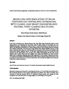
I-V and P-V Characteristics of a Photovoltaic The performance characteristics of a photovoltaic module depend on its basic materials, manufacturing technology and operating conditions. Figure 6 (a) – (d) shows typical current-voltage I-V and power-voltage P-V curves of an ICO-SPC 100W High-Efficiency Polycrystalline Photovoltaic Module according to the variation of solar radiation level and cell temperature. Three points in these curves are of particular interest: I. Short circuit point, where the voltage over the module is zero and the current is at its maximum (short circuit current Isc). Modeling and Simulation of a Solar Photovoltaic System, Its Dynamics and Transient… (M. Abdulkadir)
190
ISSN: 2088-8694
II. Maximum power point or MPP, where the product of current and voltage has its maximum (defined by Impp X Vmpp). III. Open circuit point, where the current is zero and the voltage has its maximum (open circuit voltage VD). The measurements taken for obtaining an I-V curve depend on controlling the load current. At open circuit, when no load current is generated, a first characteristic value can be measured; the open circuit voltage VD. Decreasing the load fed by the photovoltaic module leads to a decreasing voltage V with an increasing current I [12]. In other words, by increasing the load current from zero to its maximum value, the operating point moves from the open circuit voltage at zero current to the short circuit current Isc at zero voltage. The series of all measured pairs (V, I) yields the characteristic I-V curve of the module. From the characteristic curves of the module, it is clear that the open circuit voltage of the photovoltaic module, the point of intersection of the curve with the horizontal axis, varies little with solar radiation changes. It is inversely proportional to temperature, i.e., a rise in temperature produces a decrease in voltage. Short circuit current, the point of intersection of the curve with the vertical axis, is directly proportional to solar radiation and is relatively steady with temperature variations. Actually, the photovoltaic module acts like a constant current source for most parts of its I-V curve [11] – [14]. As demonstrated in Figure 6b, an increase in solar radiation causes the output current to increase and the horizontal part of the curve moves upward. An increase in cell temperature causes the voltage to move leftward, while decreasing temperature produces the opposite effect. Thus, the I-V curves display how a photovoltaic module responds to all possible loads under different solar radiation and cell temperature conditions. An operating point of a photovoltaic module will move by varying solar radiation, cell temperature, and load values. For a given solar radiation and operating temperature, the output power depends on the value of the load [25]. As the load increases, the operating point moves along the curve towards the right. So, only one load value produces a PV maximum power. The maximum power points line, which is positioned at the knees of the I-V curves, has a nearly constant output voltage at varying solar radiation conditions. When the temperature varies, the maximum power points are generated in such a manner that the output current stays approximately constant. 8
110
7
100
MPP
90 6
80 25 oC
70 25 oC
4
Power (w)
Current (A)
5
50 oC 3
60 50 oC 50
75 oC 2
40 75 oC
1
0
30 20 0
2
4
6
8
10 12 Voltage (V)
14
16
18
20
22
(a)
10 0
0
2
4
6
8
10 12 Voltage (V)
14
16
18
20
22
(b) 110
8 Isc
100
1000W/m2
7
90 6
800W/m2
80 5 Current (A)
Power (w)
70 60 50
600W/m2 4
400W/m2
3
40 2
30
200W/m2
20
VD
1
10 0
0
0
2
4
6
8
10 12 Voltage (V)
14
16
18
20
22
(c)
0
2
4
6
8
10 12 Voltage (V)
14
16
18
20
22
(d)
Figure 6. (a) I-V Characteristic for varying temperature (b) P-V Characteristic for varying temperature (c) PV Characteristic for varying irradiance (d) I-V Characteristic for varying irradiance.
IJPEDS Vol. 3, No. 2, June 2013 : 185– 192
IJPEDS
ISSN: 2088-8694
191
ACKNOWLEDGEMENTS The authors would like to thank the Ministry of Higher Education, MOHE Malaysia for the financial support and Universiti Teknologi Malaysia, UTM JB for providing the facilities to conduct the research.
REFERENCES [1] [2] [3] [4] [5] [6] [7] [8] [9] [10] [11] [12] [13] [14] [15] [16] [17] [18] [19] [20] [21] [22] [23] [24] [25] [26]
H Zang and X Yang. “Simulation and analysis of two-level photovoltaic grid-connected system”. vol. 433-440, ed, 2012, pp. 1406-1411. C González-Morán, et al. “Improved model of photovoltaic sources considering ambient temperature and solar irradiation”. 2009. T Kerzmann and L Schaefer. “System simulation of a linear concentrating photovoltaic system with an active cooling system”. Renewable Energy. vol. 41, pp. 254-261, 2012. AR Di Fazio and M Russo. “Photovoltaic generator modeling to improve numerical robustness of EMT simulation”. Electric Power Systems Research. vol. 83, pp. 136-143, 2012. Z Wang, et al. “Modeling of arbitrary power level PV array based on a circuit equivalent mechanism”. vol. 424425, ed, 2012, pp. 586-591. AC Moreira Soares, et al. “Simulation of a photovoltaic model using bisection method”. 2011, pp. 807-811. G Liu, et al. “A general modeling method for I-V characteristics of geometrically and electrically configured photovoltaic arrays”. Energy Conversion and Management. vol. 52, pp. 3439-3445, 2011. AM Yahya, et al. “Behavior and performance of a photovoltaic generator in real time”. International Journal of Physical Sciences. vol. 6, pp. 4361-4367, 2011. K Ishaque, et al. “Simple, fast and accurate two-diode model for photovoltaic modules”. Solar Energy Materials and Solar Cells. vol. 95, pp. 586-594, 2011. S Ransome. “Comparing PV simulation models and methods with outdoor measurements”. 2010, pp. 2306-2311. MG Villalva, et al. “Modeling and circuit-based simulation of photovoltaic arrays”. 2009, pp. 1244-1254. MG Villalva, et al. “Comprehensive approach to modeling and simulation of photovoltaic arrays”. Ieee Transactions on Power Electronics. vol. 24, pp. 1198-1208, 2009. O Gil-Arias and EI Ortiz-Rivera. “A general purpose tool for simulating the behavior of PV solar cells, modules and arrays”. 2008. R Chenni, et al. “A detailed modeling method for photovoltaic cells”. Energy. vol. 32, pp. 1724-1730, 2007. W Xiao, et al. “A novel modeling method for photovoltaic cells”. 2004, pp. 1950-1956. A Chouder, et al. “Modeling and simulation of a grid-connected PV system based on the evaluation of main PV module parameters”. Simulation Modelling Practice and Theory. vol. 20, pp. 46-58, 2012. G Bhuvaneswari and R Annamalai. “Development of a solar cell model in MATLAB for PV based generation system”. 2011. S Belliwali, et al. “Mathematical modeling and simulation of directly coupled PV water pumping system employing Switched Reluctance Motor”. 2011, pp. 386-390 IB Osorno. “Modeling of solar cells utilizing Pspice and Matlab-Simulink in the classroom”. 2011. W Zhu, et al. “Modeling and analysis of output features of the solar cells based on MATLAB/Simulink”. 2011, pp. 730-734 K Ding, et al. “Matlab-simul ink based modeling to study the influence of nonuniform insolation photovoltaic array”. 2011. N Pandiarajan and R Muthu. “Mathematical modeling of a photovoltaic modules with Simulink”. 2011, pp. 258263. S Rustemli and F Dincer. “Modeling of photovoltaic panel and examining effects of temperature in Matlab/Simulink”. Elektronika ir Elektrotechnika. pp. 35-40, 2011. A Elkholy, et al. “A new technique for photovoltaic module performance mathematical model”. 2010, pp. 6-10. ML Dotuabta, et al. “Lab VIEW modeling and simulation of a hydrogen-based photovoltaic/wind energy system”. 2009. Huan-Liang et al. “Development of generalised Photovoltaic Model Using MATLAB/SIMULINK” WCECS 2008, October 22-24, 2008, San Francisco, USA.
BIOGRAPHIES OF AUTHORS Musa Abdulkadir Born 1974 at Borno State Nigeria. He obtained his Bachelor degree in Electrical and Electronics Engineering at University of Maiduguri, Nigeria in 2004, Master degree in Electronics Engineering from Electrical and Electronics Engineering at University of Maiduguri, Nigeria in 2011, and currently pursuit PhD degree from Universiti Teknologi Malaysia, Malaysia. His areas of interest research include renewable energy, control technique and application of power converters.
Modeling and Simulation of a Solar Photovoltaic System, Its Dynamics and Transient… (M. Abdulkadir)
192
ISSN: 2088-8694 Ahmad Saudi Samosir was born in Belawan, Indonesia in 1971. He obtained his Bachelor degree in electrical engineering from University of North Sumatera, Indonesia, in 1995, Master degree in electrical power engineering from Bandung Institute of Technology, Indonesia, in 1999, and PhD degree from Universiti Teknologi Malaysia, Malaysia, in 2010. His areas of interest research include renewable energy, control technique and application of power converters.
Abdul Halim Mohd Yatim received the B.Sc. degree in Electrical and Electronic Engineering from Portsmouth Polytechnic, Portsmouth, U.K., in 1981, the M.Sc. and Ph.D. degrees in power electronics from Bradford University, Bradford, U.K., in 1984 and 1990, respectively. Since 1982, he has been a member of the faculty at the Universiti Teknologi Malaysia, Johor, Malaysia, where he currently is a Professor and Dean of the Faculty. His areas of interest research include power quality, renewable/alternate energy, power electronics application and drives. He was a Commonwealth Fellow during 1994–1995 at Heriot Watt University, Edinburgh, U.K., and a Visiting Scholar at the Virginia Power Electronics Centre, Virginia Polytechnic Institute and State University, Blacksburg, in 1993. Dr. Yatim is a Corporate Member of the Institution of Engineers Malaysia. He is a Registered Professional Engineer with the Malaysian Board of Engineers.
IJPEDS Vol. 3, No. 2, June 2013 : 185– 192