Modeling and Simulation of Mobile Ad hoc Networks
Modeling and Simulation of Mobile Ad hoc Networks Kayhan Erciyes1, Orhan Dagdeviren2,3, Deniz Cokuslu2,3, Onur Yılmaz 3,4, Hasan Gumus5 1 Izmir University 2 Izmir Insitute of Technology 3 Ege University 4 Izmir University of Economics 5 Aselsan Lmtd. Corparation [e-mail:
[email protected]]
Abstract A model is a simplified representation of a system that aids the understanding and investigation of the real system. Simulation is the manipulation of the model of a system enabling to observe the behaviour of the sytem in a setting similar to real-life. By modeling and simulation of a mobile ad hoc network (MANET), it is possible to simplify many difficult real-life problems associated with them. Modeling and simulation of a MANET have limitations and providing further flexibility in these such that a general MANET without much limitations can be modeled and simulated is an important research topic. In this chapter, we review network models, topology control models, mobility models and simulators for MANETs by investigating their current limitations and future trends. Keywords: Mobile ad hoc networks, modeling, simulation, network models, topology control models, mobility models, posix threads, ns2, TOSSIM, OPNET, OMNET++.
134
Modeling and Simulation of Mobile Ad hoc Networks
1. Introduction
Ad hoc networks are key to the evolution of wireless networks. MANETs are non-fixed infrastructure networks which consist of dynamic collection of nodes with rapidly changing topologies of wireless links. Although military tactical communication is still considered the primary application for ad hoc networks, commercial interest in this type of networks continues to grow. Applications such as rescue missions in times of natural disasters, law enforcement operations, commercial and educational use of sensor networks, personal area networking are just a few possible commercial examples. MANETs have the problems of bandwith optimization, transmission quality, discovery, ad hoc addressing, self routing and power control. Power control is a very important issue in MANETs because nodes are powered by batteries only. Therefore, amount of communication should be minimized to avoid a premature drop out of a node from the network. Links in a MANET change dynamically over time thus a functioning network must be able to deal with this dynamic nature. One key problem in MANETs is to model the mobile nodes and the communication edges of the network to provide a solution step for well known problems like MAC design, clustering, backbone formation, etc. These models should capture the behaviors of the wireless transmission in different conditions since wireless transmissions in a MANET operating on a flat unobstructed environment may totally differ from the wireless transmissions in an ad hoc network of nodes each located on a building. MANETs may be of large scale consisting of even hundreds of nodes operating for the completion of an application. These nodes may be small and cheap devices as well as expensive military vehicles designed for operating in harsh conditions. Scientists aim to improve the operation quality and decrease the resource usage in MANETs by researching the various topics in communication layers. These studies may include theoretical anaysis and extensive experiments to validate the superiority of the work. Since it is not feasible for researchers to afford the experiments of hundreds of moving nodes located on large areas, another key problem arises in MANETs: Providing suiable simulation testbeds. 1.1. Challenges A MANET can be modeled as a graph G(V,E) where V is the set of vertices and E is the set of edges. Two vertices (nodes) of a graph are connected only if there is a communication link between them. Once a MANET is represented as a graph, the next issue at hand is whether any graph property has any implications for the MANET. For example, a dominating set D of a graph is the set of vertices where a vertex v Є V is either in D or adjacent to a vertex in D. If vertices of a dominating set are connected, the dominating set is called a connected dominating set (CDS) and forming a CDS in the graph model of the MANET provides a communication backbone for routing purposes in the actual mobile network. However, finding a minimum DS or a CDS is an NP-Complete problem in graph theory and hence approximation algorithms for such problems where suboptimal solutions using some heuristics are usually the only choice. However, designing an approximation algorithm with a favorable approximation ratio to the optimum solution to the problem is not sufficient since one is dealing with a real network without any global information. Any algorithm employed 135
Modeling and Simulation of Mobile Ad hoc Networks
must be distributed without any global knowledge. A distributed algorithm is run by all nodes of a MANET, provides exchange of information with its neighbor nodes by message passing only and eventually results in reaching a determined state of the network [1]. Based on the above, the challenge is in fact designing of distributed approximation algorithm with a favorable approximation ratio that can be implemented on the graph model of the MANET, which provides a solution to a graph problem which is usually extremal and has implications in the real MANET environment. Some other real-life condiderations such as the battery lifetime of nodes in sensor networks or the mobility of the nodes in a MANET may have to be incorporated to the distributed approximation algorithm as the final adjustment. Another example would be the vertex cover problem in a graph. A vertex cover of a graph is the set of vertices S Є V such that any edge e is incident to at least one vertex in S. Finding a vertex cover of minimum size is NP-Complete. For a distributed robot network such as a SWAT, finding a vertex cover is equiavalent to placing robots at the corners of a maze such that every robot is in sight of at least another robot which means all robots remain connected. 1.2. Scope The scope of this chapter is to first specify basic models for MANETs. One such useful model is the graph representation and once this is done, all of the graph theoretic results become available for the MANET. The key point then is the proper choice of some useful properties of graphs for the MANET as described above and designing of efficient and scalable distributed approximation algorithms. We show in Section 3 the extremal graph problems which have direct or indirect implementations for MANETs. We then provide detailed descriptions of the simulation platforms for MANETs. Section 2 outlines models for MANETs whereas simulators for MANETs are discussed in section 3. The conclusions are drawn in section 4.
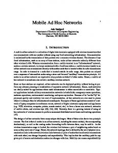
2. Modeling In this section we explain the network models, topology control models and mobility models with their current limitations and future trends in modeling. 2.1 Network Models Unit Disk Graph (UDG): A UDG is a special instance of a graph in which each node is identified with a disk of unit radius r=1, and there is an edge between two nodes u and v if and only if the distance between u and v is at most 1 [2, 3]. The model is depicted in Fig. 1.a. Each node’s transmission range is drawn as a dotted circle. The edges, which connect nodes, are drawn as straight lines. The neighbors of node u are node v, node w, node y and node z are shown in the simplified graph in Fig. 1.b. This model is very simple yet captures the behavior of broadcast radio transmission, thus it is good for modeling ad hoc and sensor networks [3]. It may be also suitable for modeling ad hoc networks located on unobstructed environments. Moreover, since this model is open for theoretical analysis due to its geometric properties, it is an important playground for the approximation algorithm designers. Efficient distributed approximation algorithms targeting to solve NP-Complete network topology control problems like finding minimum dominating 136
Modeling and Simulation of Mobile Ad hoc Networks
set and maximum independent set which will be described in the following sections are studied by the researchers. Although UDG is a widely used networking model, it has drawbacks caused by its simplicity. In real configurations, the wireless transmission may be disturbed by even small obstacles between communicating parties, therefore UDG is not a realistic model for ad hoc networks located on areas consisting of heterogenous objects. It does not model the signal quality between nodes, so it may result in poor topology control for multi-hop communication. Also it lacks modeling node weights consisting of node mobility, energy, etc. which makes UDG not suitable for the selection of routes with high weighted nodes. Fig. 1. (a) Unit Disk Graph Model (b) Node u’s Neighbors
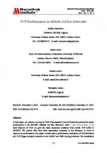
Quasi Unit Disk Graph (QUDG): In a QUDG, each node is identified with two disks, one with unit radius r=1 and other with radius q=(0,1]. It can be observed that a QUDG with q=1 is an UDG [4]. The edges between nodes d away from each other are identified with respect to the below listed rules: • There is an edge between two nodes if d=(0,q). • There is a possible edge connecting two nodes if d=(q,1] • There is no edge between two nodes if d=(1,∞] The model is depicted in Fig. 2.a. The inner circles are drawn with the dashed lines. The bold lines are communication edges and other lines are possible edges. In Fig. 2.b, the connections of node w are shown. The node y is the neighbor of node w, other nodes are the candidates for the neighborhood of node w. QUDG is an extended model of UDG in which probabilistic links can be modeled. Also in QUDG model the effect of the small obstacles located in the network area can be handled by adjusting the q parameter. Although the QUDG model has these advantages over the UDG model, the other disadvantages of the UDG model given in the previous section still exists in the QUDG model. 137
Modeling and Simulation of Mobile Ad hoc Networks
Fig. 2. (a) Quasi Unit Disk Graph Model (b) Node w’s Neighbors
Fig. 3. Undirected Graph Model
Undirected Graph (UG): An undirected graph is described as G=(V,E) where V is the set of vertices or nodes(V={V1, V2, V3, …, VN}), and E is the set of edges between these vertices (E={E12,E21,…}). Exy is an edge starting from vertice x and ending at vertice y. If there is a communication link between V1 and V2 , then E Є E12 and E21. Since the graph is undirected, links are assumed as starting and ending in both sides. An example network with 10 nodes modeled with UG is depicted in Fig. 3. In this model, the set of vertices is V={V1, V2, V3, …, V10} and the set of edges is E={E16, E61, E26, E62, …, E910,E109}.
138
Modeling and Simulation of Mobile Ad hoc Networks
The UG model is simple and very common for various types of networks. There are many cases where modeling ad hoc networks with UG is suitable. Also there is significant amount of research on UG model. In this model, the geometric properties of the wireless networks cannot be applied. Thus this model results in more complicated approximation algorithm designs with probably higher resource requirements compared to the models with defined geometric property like UDG. By not assuming a geometric wireless transmission pattern, this model may also be defined as pessimistic. One of the most important disadvantage of this model compared to UDG and partially QUDG is the undirected link assumption where in real networks it may not be realistic. Also in UG, node and edge weights can not be modeled. Fig. 4. Directed Graph Model
Directed Graph (DG): A DG is described as UG: G=(V,E) where E may contain one of Exy and Eyx. A sample DG model is given in Fig. 4. In this model, the set of vertices is V={V1, V2, V3, …, V10} and the set of edges is E={E16, E26, E38, …, ,E107}. DG is an extended model of UG which captures the behavior of the heterogenous ad hoc networks of nodes with different transmission range. In Fig. 4, the transmission ranges of the nodes are depicted with the dotted circles of different size. Like UG, DG can not assume a geometric transmission property and does not model the edge and node weights. Weighted Graph (WG): A weighted graph Gw can be node weighted graph: Gnw=(Vw,E), edge weighted graph: Gew=(V,Ew) or the combination of both: Gnew=(Vw,Ew). Also a weighted graph can be undirected weighted graph (UWG) or directed weighted graph (DWG). The weight of a node can be mobility, energy, nodal degree, etc. or a combination of all. The weight of an edge can be the signal strength, distance, etc. The weights are usually positive numbers but negative numbers may also be used. Sometimes the cost term is used instead of weight. An example directed node and edge weighted graph is depicted in Fig. 5. The transmission ranges of the nodes are not identical, thus connectivity between two nodes may be both uni-directional or bi-directional. The weight of a node in this figure is assumed as 1/energy. 139
Modeling and Simulation of Mobile Ad hoc Networks
An edge is represented with the signal strength. Like UG and DG, DWG does not use geometric properties of the wireless transmission, thus it is a pessimistic model. Fig. 5. Directed Weighted Graph Model
Fig. 6. (a) Maximal Independent Set (b) Maximum Independent Set (c) Maximum Weighted Independent Set
140
Modeling and Simulation of Mobile Ad hoc Networks
2.2 Topology Control Models Independent Set (IS): IS is a set of nodes in which none of the nodes are adjacent. If this set can not be extended by adding a new node, then IS is called the maximal IS. The IS with the greatest number of nodes is called the maximum IS. In Fig. 6.a, 6 gray filled nodes are the elements of the maximal IS. However this set can not be extended by adding a new node, removing some nodes from this set and adding other nodes may increase the size. In Fig. 6.b, the maximum IS with 8 nodes is shown. In the weighted version of this problem, a weight is assigned to each node, and maximizing the total weight of this set is targeted. In Fig. 6.c, the maximum weighted IS having 56 total weight is depicted. The IS structure is used in ad hoc networks for facility location and backbone formation. Facility location problem covers the optimal placement of facilities in order to minimize the related cost. The selected nodes for IS may communicate with each other by increasing their transmission range to deliver and route the data from the nodes not in IS. This example also covers the backbone formation operation which is the virtual path between the selected nodes. The selected nodes may be cluster heads, if network is clustered. The maximum IS problem and its weighted version is NP-hard, thus maximal IS algorithms are studied in the literature. One practical distributed algorithm proposed by Chatterjee [5] which finds maximal IS and may find maximal weighted IS if node weights are used instead of node ids. At the beginning of the algorithm, all the nodes are in the WHITE state and all of them are the candidate for the IS. If a node’s id is greater than its neighbors, it sends a IamInTheSet message and becomes an element of IS. When a node receives an IamInTheSet message, it sends a NotInTheSet message and does not become a candidate. When a candidate node receives a a NotInTheSet message, it firstly deletes the source node from its neighborhood then sends a IamInTheSet message and becomes an element of IS if a node’s id is greater than its neighbors. Two sample outputs of this algorithm are shown in Fig. 7. In Fig. 7.a, only node u constitutes IS, but when the nodes are replaced as seen in Fig. 7.b, node u and node w are elements of IS. Fig. 7. (a) Node u is in Independent Set (b) Node u and Node w are in Independent Set
Dominating Set (DS): A dominating set is a subset S of a graph G such that every vertex in G is either in S or adjacent to a vertex in S [6]. Minimum dominating set problem is NP-complete. A maximal independent set is a dominating set. Dominating sets are widely used for topology control where elements in dominating sets are selected as cluster heads [7]. Dominating sets can be classiffied into three main classes, Independent Dominating Sets (IDS), Weakly Connected Dominating Sets (WCDS) and Connected Dominating Sets (CDS) as shown in Fig.8.
141
Modeling and Simulation of Mobile Ad hoc Networks
Fig. 8. (a) Independent Dominating Set (b) Weakly Connected Dominating Set (c) Connected Dominating Set
Independent Dominating Sets (IDS): IDS is a dominating set S of a graph G in which there are no adjacent vertices. Fig.8.a shows a sample independent dominating set filled with gray. By using independent dominating sets, one can guarantee that there are no adjacent clusterheads in the entire graph. This minimizes the number of dummy clusters in the network. Weakly Connected Dominating Sets (WCDS): A weakly induced subgraph Sw is a subset S of a graph G that contains the vertices of S, their neighbors and all edges of the original graph G with at least one endpoint in S. A subset S is a weakly-connected dominating set, if S is dominating and Sw is connected [8]. Gray nodes in Fig. 8.b show a WCDS example. Although independent dominating sets are suitable for constructing optimum sized dominating sets, they have some defficiencies such as lack of direct communication between clusterheads. In order to obtain the connectivity between clusterheads, WCDSs can be used to construct clusters. Connected Dominating Sets (CDS): A connected dominating set (CDS) is a subset S of a graph G such that S forms a dominating set and is connected. Fig.8.c shows a sample CDS. CDSs have many advantages in network applications such as ease of broadcasting and constructing virtual backbones [9], however, when we try to obtain a connected dominating set, we may have undesirable number of clusterheads. So, in constructing connected dominating sets, our primary problem is the minimum connected dominating set decision problem. Wu’s distributed algorithm [10] is an important study in this field where researchers attempted to improve the performance of this work later [11, 12]. The steps of Wu’s algorithm are given below : 1. Each node u finds the set of neighbors Г(u). 2. Each node u transmits Г (u), and receives Г (v) from all its neighbors. 3. If node u has two neighbors v,w and w is not in Г (v) then u marks itself being in the set CDS. In Fig. 9, a sample output of this algorithm is shown. A detailed survey about CDS can be found in [13].
142
Modeling and Simulation of Mobile Ad hoc Networks Fig. 9. Sample Output of Wu’s Connected Dominating Set Algorithm
Spanning Tree (ST): A graph GS = (VS,ES) is a spanning subgraph of G=(V,E) if VS = V. A spanning tree of a graph is an undirected connected acyclic spanning subgraph. The spanning trees are very important structures for ad hoc networks and they are widely used for data delivery from a source to sink or to multicast. Erciyes[14] showed that constructing a spanning tree with clusters in ad hoc networks initiated from a root node is simple. The depth parameter is provided by the algorithm to adjust the diameter of the clusters. The root periodically sends a PARENT(nhops) message to its neighbors to reinitiate the operation. Each node sends the PARENT((nhops + 1)mod depth) message to its neighbors upon the first reception of the PARENT(nhops) message. The recipients of the message with nhops = 0 are the SUBROOTS; nhops < depth are the INTERMEDIATE nodes; nhops = depth are LEAF nodes. A sample spanning tree with clusters is shown in Fig. 10. Fig. 10. Sample Output of Erciyes’s Spanning Tree Algorithm
143
Modeling and Simulation of Mobile Ad hoc Networks Fig. 11. (a) An Ad hoc Network (b) Its Minimum Spanning Tree
A minimum spanning tree (MST) for a graph is a subgraph that has the minimum edge weight for maintaining connectivity. A sample MANET and a minimum spanning tree constructed can be seen in Fig. 11.a and Fig.11.b respectively. In Fig 11.b, any node, other than the leaf nodes, which are shown by black color depict a connected set of nodes. Gallager et. al. [15] proposed a distributed algorithm which determines a minimum-weight spanning tree for an undirected graph that has distinct finite weights for every edge. Aim of this algorithm is to combine small fragments into larger fragments with outgoing edges. A fragment of an MST is a subtree of the MST. An outgoing edge is an edge of a fragment if there is a node connected to the edge in the fragment and one node connected that is not in the fragment. In this algorithm, each node starts with itself as a fragment and ends with the MST as the final fragment. The authors defined three possible node states: Sleeping, Find and Found state. Initially all nodes are in Sleeping state and are either spontaneously awaken to initiate the overall algorithm or awakened by a message from another node. A node in Find state searches for the minimum-weight outgoing edge to combine with another fragment. Combination rules of fragments are related with levels. A fragment with a single node has the level L = 0. Suppose two fragments F at level L and F’ at level L’; • If L < L’, then fragment F is immediately absorbed as part of fragment F. The expanded fragment is at level L’. • Else if L = L’ and fragments F and F’ have the same minimum-weight outgoing edge, then the fragments combine immediately into a new fragment at level L+1. • Else fragment F waits until fragment F’ reaches a high enough level for combination. Graph Matching (GM): A matching in a graph G is a set of non-loop edges with no shared endpoints. The vertices incident to the edges of a matching M are saturated by M. A maximal matching is a set of edges that can not be extended by adding an extra edge. A perfect or maximum matching in a graph is a matching that saturates every vertex [6]. Maximum matching problem is in the P complexity set. An example matching, maximal matching and perfect matching are shown with bold edges in Fig. 12.a, Fig. 12.b, Fig. 12.c respectively. 144
Modeling and Simulation of Mobile Ad hoc Networks
Fig. 12. (a) Matching (b) Maximal Matching (c) Perfect Matching
If the graph is weighted and we are looking for the maximum selected edge weight, then the problem is called weighted matching. In Fig. 13.a, an example weighted matching and in Fig. 13.b, an example maximum weighted matching is shown. Like maximum matching, maximum weighted matching is in the P complexity set. Although approximation algorithms are studied for performance considerations. Hoepman proposed an 1/2-approximation algorithm for maximum weighted matching. In Hoepman’s algorithm, it is assumed that all of the nodes know their neighbors and the weights of the edges incident to them. Each node sends a request message to its candidate. The candidate is the neighbor node that is connected on the heaviest edge. If two of the nodes both receive the request message from each other, the edge connecting them is selected and they will be matched. If a node sends a request message to a matched node, the matched node will reply with a drop message. Each node uses two sets: the set of neighbors (N) and the set of requested neighbors (R). A node deletes the source of the drop message in its (N). Fig. 13. (a) Weighted Matching (b) Maximum Weighted Matching
145
Modeling and Simulation of Mobile Ad hoc Networks
Fig. 14. Clustering by Iterative Weighted Matching
Fig. 15. Sender-centric interference model and sample topology
To control the topology of an ad hoc network, weighted matching operation can be iteratively run to construct paths between nodes. Dagdeviren [16] proposed to construct the clusters and the backbone of an ad hoc network by using weighted matching. Their algorithm works in rounds and each round starts after the previous one and is completed by all cooperating nodes. At each round, each cluster head tries to merge with the adjacent cluster over the maximum weight edge connecting them. They used Hoepman’s work as the basis algorithm and also provided asynchronous operation. An example clustered network in 4 146
Modeling and Simulation of Mobile Ad hoc Networks
rounds with this algorithm is shown in Fig. 14. The selected edges are bold and the cluster heads are filled with gray. Interference Tree: Interference is one of the major challenges in wireless networks and thereby MANETs. It alters or disrupts the message as it is transmitting along a channel between source and destination. Since the message is disrupted when the interference occurs, it has to be detected and the interfered message has to be retransmitted. In particular, in multihop communications, the nodes dissipate energy and time due to interference. The interference in MANETs mostly occurs from concurrent message transmission. Since the nodes in MANETs generally use the omnidirectional antennas, the sent messages from a node are received by all nodes which are in transmission range of sender node. When two messages are sent concurrently by two neighboring nodes, they affect each other and interference occurs. Early studies on topology control algorithms mostly deal with the connectivity and sparseness of network. They consider the interference reduction implicitly and think that if the resulting topology of topology control algorithm has low node degree, the interference is solved intuitively. However, it is proved that this intuition is wrong. Recent topology control algorithms emphasize the interference reduction explicitly [17]. First topology control algorithms for interference reduction try to find an answer to question, “How many nodes are affected by communication over a certain link”. The proposed algorithms for this question are classified as sender-centric interference perspective. On the other hand, the resulting topology must have connectivity and spanner properties as well. The MANET may be modeled as an UDG. A node can adjust its transmission range zero to maximum level. A directed edge (s, r) may exist only if the maximum transmission radius of s is at least |sr| Euclidian distance. In order to provide good service to upper layer, undirected edges are used in sender-centric perspective. The goal of topology control with explicit interference reduction is to generate a subgraph via eliminating the edges which have high coverage. Coverage of an undirected edge (s, r) is number of nodes covered by disks of both s and r. In other words, coverage of the undirected edge (s, r) is the number of nodes which are affected while node s and r communicating. LIFE algorithm is proposed in order to generate an interference optimal topology [18]. The LIFE activates the edges regarding the coverage in increasing order. Fig. 15 displays a sample of sender-centric interference model on a given UDG. The values of edges indicate the coverage of the link and red edges indicate a sample of resulted topology of LIFE algorithm. Activating the edges only regarding the coverage can cause long distance communications. In order to balance the interference and communication costs, LISE algorithm is proposed which is a t-spanner algorithm. The LISE activates the edges regarding coverage and the distance of edge with constant t-stretch factor. Thus, interference and communication cost aware subgraph is constructed. New perspective for interference reduction is receiver-centric. In this approach, the topology control algorithms try to find an answer to question, “How many other nodes in a given network node can be disturbed”. By this question, topology control algorithms change their attention from sender-centric to receiver-centric perspective. It is proved that receiver-centric perspective generates lower interference optimal topologies than sender-centric. In the sender-centric perspective, the topology control algorithms compute the 147
Modeling and Simulation of Mobile Ad hoc Networks
subgraph regarding the coverage of a certain communication link but, in the receiver-centric perspective, the goal is to minimize the interference at each possible receiver. The interference of a node s is then defined as the number of other nodes that affect message reception at node s. Simply, the interference of a node can be defined as the number of disks that include node s in a given UDG. Fig. 16 displays a sample of receiver-centric interference model on a given UDG. The values of vertices indicate the number of disks that include the corresponding nodes. The Nearest Component Connector (NCC) [18] is proposed which is based on receiver-centric perspective particularly for wireless sensor networks. The NCC algorithm generates a subgraph via connecting the components to their nearest neighbors. A component is a single or group node. The algorithm constructs a tree towards sink in several rounds. Fig. 16. Receiver-centric interference model
New trend in interference aware topology control algorithms is to construct a topology regarding signal-to-interference-noise ratio (SINR) model instead of graph theoretic models. Fig. 17. (a) Vertex Cover (b) Weighted vertex cover
Vertex Cover: A vertex cover is a subset of vertices of V that includes at least one of the vertices (u,v) in set E. Vertex cover can be used for the facility location problem. Finding minimum vertex cover problem is NP-Complete. The weighted version of the problem works on vertex weighted graph model and aims to minimize the total cost of the set. Fig. 17.a shows 148
Modeling and Simulation of Mobile Ad hoc Networks
a sample vertex cover, Fig. 17.b shows a sample weighted vertex cover with gray filled nodes. Fig. 18. (a) Pricing method (b) Graph matching method
One of the most important central methods for finding the weighted vertex cover is the pricing method which has an approximation ratio of 2. In this method, initially all vertices are relaxed. Then the edges are chosen randomly and they are given weights as much as possible providing that the total weight of the edges incident to a vertex does not exceed the weight of the vertex. When there is no edge obeying this rule, the algorithm is finished. When the total weight of the edges incident to a relaxed vertex exceeds the weight of the vertex, it becomes tight. The set of tight nodes is the vertex cover. The weighted graph matching is the other method for finding weighted vertex cover. Selecting one end point of each edge of the maximal weighted graph matching yields a weighted vertex cover. Fig. 18.a shows a sample output of the pricing method, Fig. 18.b shows a sample output by the graph matching method. Steiner Tree: A Steiner tree connects the nodes in T which is a subset of V. Steiner tree may be used to connect the nodes in a dominating set to construct connected dominating set. Finding minimum Steiner tree is an NP-Complete problem. An example Steiner tree is shown in Fig. 19.a where V={a, b, c, d, e, f} is connected by vertices v and x. Fig. 19. (a) Steiner Tree (b) Weighted Steiner Tree
In Steiner tree problem, nodes and edges may be weighted. Klein and Ravi [19] proposed a central algorithm for node weighted Steiner tree problem working on undirected weighted graphs which has an approximation ratio of 2 ln (S) where S is the minimum weight. In this algorithm, the vertices in V which have a path only consisting of them are inserted in a tree. If a vertice has no neighbor in V, then the vertice itself constitutes a tree. The weight of each vertice in V is assigned 0. The weight ratio of each vertice in S/V is calculated as the weight of 149
Modeling and Simulation of Mobile Ad hoc Networks
the vertice/the number of total vertices to be connected. The vertice with the smallest weight ratio in S/V is chosen as the connector vertice, the neighboring trees are connected and the connector is inserted to V. This operation continues until all the vertices in V are in the same tree. Fig. 19.b shows an example output of this algorithm where black filled nodes are the connectors, gray filled vertices constitute the initial V. 2.3. Mobility Models Mobility models are designed to represent the movements of mobile users, and how their location, acceleration change over time. They are used to evaluate the performance of ad hoc network protocols. Since the performance of protocol depends on the mobility model, it is important to choose the suitable model for the evaluated protocol. Various mobility models have been proposed so far but the most common ones are are Random Waypoint, Random Direction and Gauss-Markov mobility models [20]. Random Waypoint Model: The Random Waypoint Model is currently a benchmark mobility model. It is a basic model which describes the movement pattern of nodes where mobile nodes randomly designate a destination in the simulation plane. Then, each mobile node goes to designated destination with a constant velocity which each mobile node chooses randomly. Every node is independent in the plane. When the node arrives at the destination, it waits for a designated time and if the pause time is equal to zero then, this means that the node has a continuous mobility. The two important parameters of Random Waypoint Model is velocity and pause time of each node. These parameters affect the performance of the evaluated protocol. If the simulation of velocity is small and pause time is long, a stable topology is formed. Otherwise, a dynamic topology can be formed. Various topologies can be obtained by varying these parameters [20]. Random Direction Model: Random Direction Model is similar to Random Waypoint Model but in Random Direction Model, the node randomly and uniformly selects a direction by it travels until it reaches the boundary, instead of selecting a random destination. Upon reaching the boundary, the node waits for designated time. Then, it randomly and uniformly selects another direction to travel. Therefore, a uniformly distributed mobility model is provided for evaluations [20]. Gauss-Markov Model: The Gauss-Markov Model is a different model from Random Waypoint and Direction Model in terms of velocity management. In this model, the velocity of mobile node is correlated over time and Gauss-Markov stochastic process. Gauss-Markov stochastic process satisfies the requirements for both Gaussian processes and Markov processes. The velocity of mobile node at time slot t is dependent on the velocity at time t – 1. Therefore, Gauss-Markov Model is a dependent mobility model where the dependency is determined by the parameter α which affects the randomness of Gauss-Markov process. By tuning this parameter, different mobility model are provided [20]. 2.4 Current Status and Future Trends in Modeling In this section, we describe the current status, limitations and future trends in modeling. We discuss the network models, topology control models and mobility models.
150
Modeling and Simulation of Mobile Ad hoc Networks
Unit disk graph model is not realistic in some cases, does not model node and edge weights, does not provide probabilistic link modeling, does not model heterogenous ad hoc networks where nodes have different transmission range. Although unit disk graph has these limitations, it is popular for modeling ad hoc networks located on unobstructed environments since it models the simple wireless transmission. Quasi unit disk graph has the same limitations as the unit disk graph except it provides probabilistic link modeling in order to provide the wireless transmission behavior when the networking area has small obstacles, however, it is not a popular model like unit disk graph. Undirected graph model does not use geometric properties of the wireless transmission, does not model node and edge weights, does not provide probabilistic link modeling and does not model heterogenous ad hoc networks. Although undirected graph has these limitations, it is a very popular model that fits various types of networks in many cases. We think that this model will preserve its popularity and researchers will continue studying these model. The directed graph has same limitations as undirected graph model except it models heterogenous ad hoc networks. Directed graph is not a widely used model, one of the main reasons being the hardness of the algorithm design on this model. Since heterogenous ad hoc networks are increasingly becoming more popular, this model will probably receive more attention in future. The weighted directed graph model extends the directed graph by modeling node and edge weights. Alhough it has so many advantages over the other models, algorithm design on this model is very hard compared to the other models. However, it will be an important model for advanced protocol design in heterogenous ad hoc networks. Table 1 provides a summary of current limitations and future trends in network modeling. Table 1. Current Limitations and Future Trends in Network Modeling
Model Unit Disk Graph
Quasi Unit Disk Graph Undirected Graph
Directed Graph
Current Status and Limitations • Not Realistic • Lacks modeling node and edge weights. • Lacks providing probabilistic link modeling. • Lacks modeling heterogenous ad hoc networks where nodes have different transmission range. Same as Unit Disk Graph except it provides probabilistic link modeling. • Lacks using geometric properties of the wireless transmission. • Lacks modeling node and edge weights. • Lacks providing probabilistic link modeling. • Lacks modeling heterogenous ad hoc aetworks where nodes have different transmission range. Same as Undirected Graph model except it models heterogenous ad hoc
Future Trends Will still be a popular model.
This model will attract researchers. Will still be a popular model.
With the increasing popularity of the heterogenous ad hoc 151
Modeling and Simulation of Mobile Ad hoc Networks
networks. Weighted Directed Graph
networks, this model will take more attention. Same as Directed Graph model except With the increasing popularity it models node and edge weights. of the heterogenous ad hoc networks, it will be an important model for advanced protocol design in heterogenous ad hoc networks.
The distributed algorithms proposed for independent set and dominating set topology control models generally work on unit disk graphs and undirected graphs. With the increasing types of realistic network models, we think that the researchers will study these problems on other network models other than unit disk graphs and undirected graphs.Weighted versions of these problems are open research topics and in general, are more difficult to model in a MANET. Fault tolerant structures like k-connected m-dominating set will also be an important research topic. The proposed spanning algorithms generally work on undirected graphs. As independent set and dominating set problems, this problem will be studied in other networking models and node and edge weighted tree construction may be one of the important research topics in future. Graph matching is a new topology control model in which there is only very few studies [16]. The approximation ratio and the resource usage of the of this study is open for the improvements. Interference tree is another new model in which there is no algorithm for preventing interference and currently, SINR based scheduling algorithm for preventing interference is an important research topic. There are few studies related to constructing vertex cover in MANETs. Since vertex cover is an appropriate solution for the facility location problem, we think that the researchers will study this model on different network models and also on MANETs. We also believe that the node and edge weighted version of the Steiner tree problem is immature. Since the Steiner tree is used as a step for connected dominating set, especially the weighted version as related to the connected dominating set problem is an open research area that requires further investigation. Table 2 summarizes the current limitations and future trends in topology control modeling. Table 2. Current Limitations and Future Trends in Topology Control
Model Independent Set and Dominating Set
Current Status and Limitations Distributed algorithms proposed in this area generally work on UDG and UG.
Spanning Tree
Distributed algorithms proposed in this area generally work on UG.
Future Trends • Other network models than UDG and UG need further research. • Weighted versions of the problems are open research topics. • Fault tolerant structures like k-connected m-dominating set will be important research topics. • These problems on other network models than UG need further research. • Node and edge weighted 152
Modeling and Simulation of Mobile Ad hoc Networks
Graph Matching
There is only 1 proposed study.
Interference Trees
There is no algorithm for preventing interference.
Vertex Cover
There are few studies for constructing vertex cover in MANETs. The node and edge weighted version of the problem is immature.
Steiner Tree
tree construction will be an important research topic. The approximation ratio and the resource usage of the previous work is open for the improvements. SINR based scheduling algorithm for preventing interference is an important research topic. Research on different network models is needed. The Steiner Tree as related to the CDS problem problem should be studied.
The random waypoint and random direction mobility models limited by poor choice of velocity distribution, the mobility behavior of the nodes are independent and there is no geographic restrictions of movements. In spite of these disadvantages, these models are used as benchmark models since they are simple and easy to implement. Due to these facts we think that the researches will continue to use these models. The Gauss-Markov model is limited by the geographic restrictions of the movements. Since this model has a temporal mobility dependency, we think that this model will take attention by the researchers. Table 3 summarizes the current limitations and future trends in mobility modeling. Table 3. Current Limitations and Future Trends in Mobility Models
Model Random Waypoint and Random Direction
Gauss-Markov
Current Status and Limitations • It provide poor choice of velocity distribution. • The mobility behavior of the nodes are independent. • There is no geographic restrictions of movements. There is no geographic restrictions of the movements.
Future Trends The researches will continue to use these models.
This model attention.
will
take
2.5 Distributed Algorithm Model A distributed system consists of communicating devices over a network to achieve a common goal. In contrast to central systems where the data may be stored in a single device, in a distributed system, generally a device has limited and incomplete view of the network such as knowledge of its immediate neighbors. A distributed system is prone to faults in the individual devices which should be tolerated for robust operation. MANET, Grid, wireless sensor network are examples of the distributed systems. 153
Modeling and Simulation of Mobile Ad hoc Networks
A distributed algorithm is designed to run on a distributed system in which each device starts in an initial state Si Є S, can be in one of the states in S at any execution instance, changes its state from Si to Sj and may output an On Є O after receiving an input Ik Є I according to defined state transition procedures. In this manner, a distributed algorithm can be modeled as a Mealy finite state machine. An input can be an interval event such as a timer interrupt can be an external event such as a failure in one of the neighbors, can be a message received from a neighbor or from another process running in the same device. In asynchronous communication, the devices are not coordinated; on the other hand the operation is divided into rounds in synchronous communication where each operation step is executed in a round. A distributed algorithm may be initiated by a single device or by the multiple devices and synchronously or asynchronously. For example, in a synchronous distributed spanning tree algorithm initiated by a single device, a START message may be sent from a root device in the first round which is then forwarded to all devices in latter rounds. Each device may set its parent upon receiving the first START message. The algorithm is terminated after all the rounds are executed. Such an algorithm is called synchronous single initiator distributed algorithm (SSI). In an asynchronous distributed spanning tree algorithm initiated by a single device which is an example of the asynchronous single initiator distributed algorithm (ASI), the root device initiates a flooding of START message where the algorithm may have no bound on the time to complete this operation. Each device sends an ACCEPT message upon receiving first START message and otherwise sends a REJECT message. In an asynchronous distributed algorithm initiated by multiple devices, called asynchronous concurrent initiator distributed algorithm(ACI), multiple root devices may flood START message in which ordinary devices may receive START messages from different originators that may cause fragmentation of the network at an instance of the execution. These fragments may be merged by applying additional rules on the asynchronous spanning tree algorithm with single initiator, for example the device with the greatest id can be selected as the root. These three operation modes form the basis for distributed algorithm models in a mobile ad hoc network.
3. Simulation Wireless communication technology has become an essential framework for today’s communication environments. This interest leads the researchers to improve the current wireless technology. Most of today’s wireless devices are, in some sense, limited by their need for infrastructure. Today’s most popular approach for the non-fixed infrastructure is the Ad hoc networking which can be considered as a solution to the infrastructure limitations of the wireless technology. Generally in a MANET, the nodes are dynamically moving without any boundary limitations. With the growth of the scale of today’s MANETs, evaluations, experiments and comparative studies become harder to implement in real environments. Even if the underlying environment permits distributed applications to be tested, it is not practical to realize everyday experimentation of distributed applications on the real environments, especially if the application is still under construction. Moreover, implementing and testing some applications in the real environment might not be possible at all due to practical considerations. To cope up with such problems, simulators are widely used in today’s research community. In this chapter, we describe different simulation environments. In section 3.1 an overview of the simulation environments is given. In later sections POSIX threads based simulators, ns2, TOSSIM, OPNET, OMNET and other simulators are examined. Finally, current limitations and future trends are discussed in section 3.8. 154
Modeling and Simulation of Mobile Ad hoc Networks
3.1 Simulation Environments Overview The main purpose of simulation environments is to provide a virtual platform to the distributed applications with the required components. For MANETs, the detail level of simulation environments, in most cases, determines the literalness of the experiments. However, it does not mean that the simulation environments are evaluated regarding to their detail levels. Mostly speaking, simulation is a resource consuming job. The challenge is to provide equilibrium between detail and performance. The existing simulators provide users different levels of detail by providing different realistic layers in the Open Systems Interconnection model (OSI model). The decision is left to users since each application needs different components of simulated environment. Some researchers prefer to use their own simulation environments such as threads or shared memory architectures, whereas some others use other simulators, which provide more details in the OSI layers. 3.2. POSIX Threads Based Simulator In today’s research community, especially in distributed computing domain, simulators are highly utilized to test and evaluate studies. Many researchers create their own simulation environment for many reasons. For that purpose, threads, which are provided by operating systems, are very powerful tools to create application specific simulation environments. A thread is the smallest unit of processing that can be scheduled by the operating systems. Threads are created at their parent process’ context and can be scheduled as different processes. They can share the same resources provided by their parent process and are very suitable for simulating message-passing environments using the shared memory space. POSIX Thread is an API for creating and manipulating threads. Implementations of the API are available on many Unix-like POSIX systems such as FreeBSD, NetBSD, GNU/Linux and Mac OS X. Some variations of POSIX Threads also exist for Microsoft Windows and Solaris based operating systems. POSIX Thread based simulators have many advantages and drawbacks. They can be preferable in many cases in which existing simulators remain insufficient for the user’s protocol. They can also be favorable because of their simplistic implementation. On the other hand, since they do not provide any standardized environment, comparative studies may not be trustworthy compared to known existing simulators. In POSIX Thread based simulators each node is represented by a thread. Protocols are coded into the thread’s start routine and communication between threads is handled by shared memory spaces such as globally defined arrays. The issue that must be taken into consideration in thread based simulators is the mutual exclusion problem. For this problem, an inter-process communication module is recommended to handle mutual exclusion between threads as in [21]. Topology and scenario generation in such simulators can be developed explicitly from the simulator. Generally the topology is stored in two-dimensional arrays indicating the neighboring status of nodes. On the other hand, mobility scenarios can be realized by reasonably altering the neighbor matrix. 155
Modeling and Simulation of Mobile Ad hoc Networks
3.3. ns2 Simulator ns2 (Network Simulator 2, version 2.34) [22] is a discrete event simulator which is developed at ISI, California. ns2 provides substantial support for simulation of TCP, routing, and multicast protocols over wired and wireless (local and satellite) networks. ns2 began its development in 1989 as a variant of the REAL network simulator [23]. In years it has evolved substantially and in 1995, ns2 development was supported by DARPA through the VINT project at LBL, Xerox PARC, UCB, and USC/ISI. Currently ns2 development is supported by DARPA with SAMAN and by NSF with CONSER, both in collaboration with other researchers including ACIRI. ns2 has included substantial contributions from other researchers, including wireless code from the UCB Daedelus and CMU Monarch projects and Sun Microsystems. ns2 Overview: The ns2 is a de facto standard simulator in experimenting wired and wireless network applications since it is an open source and powerful tool in simulating networks. Although its early versions are aimed at wired networks, the wireless network support is added later by various extensions. It closely follows the OSI model. It is an object oriented simulator written in C++ with an OTcl interpreter as a frontend. ns2 uses two languages, C++ and OTcl. Users implement their applications in C++ and simulation scenarios and set-up are written in OTcl. Presently, the simulator is a single-threaded event driven simulator, and only one event can be executed at a time. If more than one event are scheduled to execute at the same time, the built-in scheduler executes them in a first-come first-served fashion and the next earliest event in the queue is executed to completion. Nodes in ns2 are OTcl classes, which contain an address or id, a list of neighbors, a list of agents, a node type and a routing module. The id of nodes is a monotonically increasing integer starting from 0. In later versions of ns2, node class is extended to cover mobility support. The extended class is named mobilenode. The network stack for a mobilenode consists of a link layer (LL), an ARP module connected to LL, an interface priority queue (IFq), a MAC layer and a network interface (netIF), all connected to the channel. These network components are created and brought together in OTcl. Routing of messages is handled by five alternative ad-hoc routing protocols: Destination Sequence Distance Vector (DSDV), Dynamic Source Routing (DSR), Temporally Ordered Routing Algorithm (TORA), Adhoc On-demand Distance Vector (AODV) and Protocol for Unified Multicasting Through Announcements (PUMA). By default, nodes in ns2 are constructed for unicast simulations. In order to enable multicast simulation, the simulation should be created with an option "-multicast on". Protocol Implementations: ns2 allows users to implement different protocols. Besides newly created protocols, all the internal protocols can be modified according to users needs. Simulation in ns2 is realized in 3 steps. In the first step, the user implements the protocol by writing C++ and OTcl codes to the ns2 source base. In the second step, simulation is described by using an OTcl script. In the last step, user runs its protocol in ns2 and collects results by using either trace files, which are generated by ns2, or protocol’s outputs which are generated by output commands coded into the protocol’s implementation. The protocol should be 156
Modeling and Simulation of Mobile Ad hoc Networks
written in C++ under any folder structure as long as the path is added to the makefile of the ns2. The protocol is tied to mobile nodes individually by the use of OTcl script prepared for the simulation. The OTcl script contains nodes’ initializations such as channel type, radio propagation model, network interface type, MAC type, interface queue type and size, link layer type, antenna model and routing protocol. It also contains nodes’ initial locations and movement scenarios, dimensions of the area that the nodes are moving and start-end times of the simulation. After the creation of the nodes in the OTcl file, each node can be individually tied to different (or the same) protocols using loops. Upon execution of the simulation, the OTcl script file is traced sequentially, and nodes are created and configured as indicated in the script. Then the simulator executes indicated protocols in tied nodes as indicated in the script. From this point, the nodes execute their related protocol, and can communicate to each other within their transmission range. The execution of the implemented protocols can be monitored in a number of ways. Generally, trace data is either displayed directly during execution of the simulation, or stored in a file to be analyzed later on. There are two primary types of monitoring capabilities currently supported by the ns2. The first, called traces, record each individual packet as it arrives, departs, or is dropped at a link or queue. The second, called monitors, record various interesting quantities such as packet and byte arrival and departure numbers, etc. Independently from these two trace methods, users may implement their own debugging methods into their protocols to output user specific events. Scenario Generations: The mobile node is designed to move in a three dimensional topology in ns2. However the third dimension (Z) is not used. That is, the mobile node is assumed to move always on a flat terrain with Z always equal to 0. The node movement scenarios are handled in two different alternatives, in the first alternative, nodes' speeds, starting and ending positions are selected randomly. At a pre-determined time, the node would start moving from its initial position towards its destination at the defined speed. The movement scenario is generally stored in a separate file. In the second alternative, nodes' starting positions are generated initially; the destination and speed values are dynamically updated in a random manner during the simulation. ns2 also provides network traffic patterns. The traffic generator can be used in order to generate both constrant bit rate and TCP connection scenarios. Besides the internal scenario generator, third party applications are available to generate wireless mobile scenarios for ns2 in the Internet. Mobility Support: ns2 has mobile networking support by extending the standard ns2 release using CMU’s Monarch group’s mobility model. In the extended version, the node class is improved by adding more supporting features such as ability to move within a given topology, ability to send and receive packets over a wireless channel etc. The core difference between a node and a mobile node is that a mobile node is not connected to other nodes by links. The connectivity of nodes are determined by their positions and transmission ranges. Routing mechanisms and network components are also extended to include all mobile networking properties such as wireless channel, network interface, radio propagation model, MAC protocols, interface queue, link layer and address resolution protocol model (ARP). The original CMU’s Monarch group’s mobility model is designed to provide pure wireless support. The extensions in ns2 allow users to combine wired and wireless networks together to create more realistic simulation environments.
157
Modeling and Simulation of Mobile Ad hoc Networks
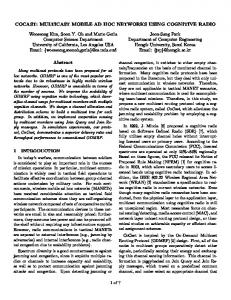
3.4. TOSSIM Simulator TinyOS and TOSSIM overview: TinyOS [24] is a sensor network operating system that runs on motes and TOSSIM is a discrete event simulator [25] for TinyOS for wireless sensor networks which were developed at UC Berkeley. Motes are tiny sensor nodes with limited resources. The TinyOS has a component-based programming model and uses a language called nesC which has a C-like syntax, and it supports the TinyOS concurrency model, as well as mechanisms to provide robust embedded programming [24]. TOSSIM is designed considering four requirements, which are essential for efficient TinyOS simulation environment. First, scalability: The simulator must be able to handle large scale sensor networks. Secondly, completeness: The simulator must cover as many system interactions as possible. Third, fidelity: The simulator must capture the network behavior accurately. Fourth, bridging: The simulator must bridge the test implementation and the real implementation. TOSSIM has visual components to improve its usefulness. The TOSSIM architecture is composed of five parts: a compilation support for simulation, a discrete event queue, a small number hardware abstraction components, mechanisms for extensible radio and ADC models, and communication services. Fig. 20 shows the graphical overview of TOSSIM architecture [26]. Fig. 20. TOSSIM Architecture: Frames, Events, Models, Components, and Services [26]
A TinyOS program is composed of components, which are independent computational entities. Components have three computational concepts: commands, events, and tasks. Commands and events are used for inter-component communication, while tasks provide intra-component concurrency. The component model, which is designed in TinyOS, allows the target platform to be easily changed from mote hardware to simulation mode. TOSSIM models the characteristics of the underlying hardware in software. To model hardware interrupts, a simulator event queue is located in TOSSIM that delivers the interrupts. This 158
Modeling and Simulation of Mobile Ad hoc Networks
event queue is one of the most important components of the TOSSIM. TinyOS abstracts each hardware resource as a component and TOSSIM emulates the behavior of the underlying raw hardware such as ADC, clock, EEPROM. The TOSSIM architecture includes two different models: ADC Models for the Analog-Digital-Converter and radio models for all kinds of transmissions. In TOSSIM, a network signal can be either 0 or 1. TOSSIM provides two built-in radio models: simple radio model which simulates error-free transmission, and lossy radio model which simulates packet loss in probabilistic manner (yukarısının aynı). Radio model can be easily changed for specific simulations. The default TOSSIM radio model is signal-strength based lossy model. In default model, the propagation strengths, noise floor and receiver sensitivity are provided to the Simulator. TOSSIM models ADC (Analog-Digital-Converter) hardware in two different ways. First one is random, which generates random 10 bit random value upon sampling ADC channel. The other is the generic way which works like random one and also it can be actuated by external applications. TOSSIM provides the communication of the applications running on a PC with simulation over TCP/IP [26]. Protocol Implementations: TOSSIM simulates TinyOS’s networking stack, which is the most complex system of TinyOS. It is composed of 12 components. Networking stack uses CSMA protocol and single error correction/double error detection data encoding with a full-packet CRC. One of the most interesting features of TOSSIM is the bit-level simulation of the network stack. Understanding network stack simulation of TOSSIM requires knowledge of TinyOS network stack implementation. TinyOS network stack handles MAC and single hop packet transmission. It uses Active Message (AM) as packet abstraction and AM packets provide an unreliable data link protocol. Packets provide precise timestamps and synchronous data-link acknowledgements. TOSSIM’s bit level simulation of the TinyOS networking stack results in a realistic simulation environment. Hidden terminal problem is accurately simulated and errors at all phases of packet reception are included in the environment. Signal corruption is observed by a listening node, upon two sender nodes’ concurrent transmissions. Listener node receives union of the two sender’s bits as a result of interference. Moreover, a delay is occurred when motes repeatedly enter CSMA wait, because they continue to hear a signal on the channel. A single bit error during the data phase can be handled with the data encoding, but a single bit error during start symbol detection will prevent reception and a single bit error during acknowledgment transmission will cause to failure. This granularity changes the methodology with which one normally approaches network simulation. For example, instead of modeling latency, by modeling the network itself, TOSSIM simulates contention and backoff, which are causes of latency [26]. Table 4. Sample topology file for TOSSIM
1 2 1 3 2 3
2 -54.0 1 -55.0 3 -60.0 1 -60.0 3 -64.0 2 -64.0
Scenario Generations: Scenario generations in TOSSIM consist of four stages. In the first stage, the predefined topology file is loaded to the nodes. In the second stage, noise traces are 159
Modeling and Simulation of Mobile Ad hoc Networks
assigned to the nodes. In the third stage, nodes are booted at particular times and finally in fourth stage, packets are injected to simulation if necessary. Network topology has to be specified in prior in order to simulate the network behaviour. Topology definition can be in different formats and can be stored in text files. TOSSIM loads topology file using Python scripts. One example topology format which defines each link in a line with three values, the source, the destination and the gain, for instance, {1 2 -54.0} indicates that node 2 receives transmissions from node 1 at -54 dBm. A sample topology file is given in Table 4. Topology file shown in Table 4 can be generated using “LinkLayerModel”, general link-layer model proposed by the ANRG group at University of Southern California. It is valid for static and low-dynamic environments. The configuration file contains various channel, radio and topology parameters that can be modified. Using topology parameters, different deployments can be specified as grid, uniform or random. Number of nodes, terrain dimensions etc. are also specified in topology file as topology parameters [27]. Table 5. Noise trace sample from Meyer-heavy model
39 98 98 98 99 98 94 98 98 98 In addition to the radio propagation model, TOSSIM also simulates the radio frequency noise and interference a node hears, both from other nodes as well as outside sources. It uses the Closest Pattern Matching (CPM) algorithm. CPM takes a noise trace as input and generates a statistical model from it. This model can capture bursts of interference and other correlated phenomena, such that it greatly improves the quality of the RF simulation. CPM requires a noise trace to be configured. TOSSIM provides some sample noise traces, which are a series of noise readings. For example, in Table 5, first 10 lines of a sample noise trace file is given, which is a noise trace taken from Meyer Library at Stanford University [28]. TOSSIM is capable of injecting packets into the network dynamically. Packets can be scheduled to arrive at any time. A node can receive an injected packet, even if it is in the middle of receiving a packet from another node over radio [28]. Mobility Support: In earlier versions of TOSSIM, before version 2.1.0, mobility was supported. However, mobility support is not included in last version of TOSSIM, (version 2.1.0), due to radio model changes in implementation. Considering lack of mobility in TOSSIM 2.1.0, Stevens C. et. al. designed and implemented a mobility extension for the last release of TOSSIM. Evaluating the results of TOSSIM 2.x with mobility extension, Stevens C. et. al. conclude that their implementation correctly demonstrates the expected behaviour of mobile wireless nodes [29]. 160
Modeling and Simulation of Mobile Ad hoc Networks
3.5. OPNET OPNET is a high level event based network simulator [30]. The development of OPNET was started by MIL3 Inc. but nowadays, OPNET Technologies Inc. is conducting the development. It is a commercial simulator, but there is free licience for educational purposes. Originally, the simulator was developed for military operations. OPNET accelerates the R&D process for analyzing and designing communication networks and protocols. It is a very large and powerful network simulator with variety of possibilities such as simulating entire heterogeneous networks with various protocols. It consists of user friendly user interface, which is constructed from C and C++. The GUI-based debugging and analysis simplify the simulation process. OPNET provides variuos tools for simulation including network model editor, node model editor and process model editor. It has the fastest discrete event simulation engine among leading industry solutions. One of the significant features of OPNET is that supports grid computing for distributed simulations. 3.6. OMNeT++ OMNeT++ is a modular object oriented discrete event network simulator [31]. It has been developed by András Varga at the Technical University of Budapest, Department of Telecommunications. OMNeT++ is the extended version of Omnet which was developed by Dr. György Pongor. The OMNeT++ can perform various network simulations such as traffic modeling of telecommunication networks, protocol modeling, modeling queueing network, MANET etc. An OMNeT++ model consists of hierarchically nested modules which are managed with a high-level script language (NED). Modules communicate through message passing. Modules can have their own parameters and they can be used to customize a module. The modules are programmed in C++ using the simulation library. OMNeT++ simulations can feature varying user interfaces for different purposes including debugging, demonstration and batch execution. Eclipsed-based IDE provides easy control over simulation execution. In addition, the IDE allows the user development/debugging phase for the simulation project. User interfaces also facilitate demonstration of how a model works. The simulator as well as user interfaces and tools are portable: they are known to work on Windows and on several Unix flavours, using various C++ compilers. OMNeT++ also supports parallel distributed simulation. OMNeT++ runs on Linux, Mac OS X, other Unix-like systems and on Windows but the IDE only runs on Linux32/64, Mac OS X 10.5 or Windows XP. OMNEST is the commercially supported version of OMNeT++. OMNeT++ is only free for academic and non-profit use but for commercial purposes, OMNEST licenses from Omnest Global, Inc have to be obtained. 3.7. Other Simulators Other than the well-known network simulators including ns-2 and OMNeT++, there are other network simulators which have wide use such as GloMoSim [32], Sinalgo [33] and GTNetS [34]. These network simulators are increasingly being used by academic research 161
Modeling and Simulation of Mobile Ad hoc Networks
groups. GloMoSim is a scalable parallel discrete-event simulator for wired and wireless networks. The protocols are performed by Parsec which is a C-based simulation language, developed in UCLA. GloMoSim has a layered approach like the OSI network architecture. Currently, GloMoSim supports protocols for a purely wireless network but, the wired and hybrid network have not yet been accomplished. Sinalgo is a network simulator for testing and validating network protocols and algorithms. It was developed by the Distributed Computing Group at ETH Zurich and published under BSD license. It focuses on the verification of network algorithms. It tends to simulate the wireless networks and offers itself as a first test environment, prior to the deployment of the algorithm to the hardware. It provides a close environment to the real hardware devices. It has important features including quick prototyping of the network algorithms, many plug-ins, working over 100000 nodes, 2D and 3D support, asynchronous and synchronous simulation and, customizable visualization of the network graph. Sinalgo contains the most frequently used modes such as UDG and QUDG. The GTNetS is a simulation environment which provides a protocol stack like OSI reference model. It has variety of features that offer researchers the ability to experiment in large scale networks. 3.8. Current Status and Future Trends Each simulator tool has its own advantages and drawbacks in different aspects. In these simulators, many protocol implementations can be realized and simulated. Even these simulators provide powerful environments; nearly all of them lack important details related to real life experiments. In ns2, the most important missing detail may be considered as the signal propagation and environmental aspects. The simulated environment is assumed to be a flat empty area in which mobile nodes move without interference in their signals. In reality, environment consists of buildings, people, moving vehicles, plants etc. that affects the signal propagation of wireless mobile devices crucially. Moreover, the distance between wireless devices affects the signal level and transmission speeds drastically, which is not considered in the current version of ns2. Instead, the transmission capacity drops from full to zero immeditely as the nodes apart from their coverage areas. This phenomenon brings the impossibility to simulate proximity and environmental noise related simulations. Additional to these limitations, ns2 cannot easily handle large scale simulation scenarios. ns2 simulations can be very resource consuming when the number of simulated nodes increase. It may consume a very large amount of memory once the number of nodes exceeds several hundreds. Although there is a workaround on parallelizing ns2 (PDNS) [35], users prefer to keep using ns2 and restrict their evaluations to smaller networks. Besides the memory leak problem, in general, depending on the simulation setup, ns2 is limited to simulate hundreds of nodes. because of stack overflow problems. A comparative study and scalability limitations of ns2 can be found in [36]. This scalability issue can be a decisive factor in some situations in which large scale simulations are required. Another limitation with ns2 is its complex implementation. Developing new networking protocols and creating simulation scripts are complex tasks, which requires understanding of 162
Modeling and Simulation of Mobile Ad hoc Networks
the ns2 class hierarchy, C++, and Tcl programming. ns2 has a very complex hierarchy which is hard to learn at a glance. Learning ns2 in its simplest form may take weeks depending on the background of the implmenter. Moreover, debugging and output tracing is not straightforward, and requires additional efforts. Although there are visualisation tools for ns2 such as Nsnam [22], in general, tracing the results requires parsing an output file generated by the protocol itself. TOSSIM can simulate large-scale sensor networks up to thousands of nodes. Its bit-level radio modeling allows simulating signal interference. Moreover, bridging capability of TOSSIM allows developers to test and verify the code that will run on hardware motes. As a drawback, TOSSIM is currently implemented only for mica platforms. In addition, TOSSIM lacks mobility support in its latest version TOSSIM 2.x. One more notable drawback of TOSSIM is a simulator-specific and simplified implementation of the MAC layer. Similar to ns2 and TOSSIM, OMNeT++, GloMoSim, Sinalgo and GTNetS lack in terms of the environmental effect to signal propagation. Between these network simulators, OMNeT++ comes forward since it provides testing environments to all kind of networks. In addition, the Eclipse-based IDE makes easy to debug, develop and test the network algorithms and protocols. The limitation of OMNeT++ is that it supports up to nearly 2000 nodes in simulations. OMNeT++ have found acceptance from network research community and it will be widely used by researchers. GloMoSim is a developing network simulator and it currently cannot simulate wired networks. Sinalgo offers a good simulation environment specifically for MANETs. It supports large numbers of nodes in the simulations and contains well-known models. We believe that Sinalgo will take the attention from researchers. One of the disadvantages of Sinalgo is that it is not being widely used. Thus, the performance and usage of Sinalgo is not known enough. Currently, GTNetS has not found enough acceptance from the research community as well. Lastly, OPNET lacks to support the recent wireless networks. It is a commercial simulator and licience is quite expensive. Table 4. Current Limitations and Future Trends in Simulation
Model ns2
•
•
•
• • •
TOSSIM
Current Status and Limitations The simulated environment is assumed to be a flat empty area in which mobile nodes move without interference in their signals. The distance between wireless devices affects the signal level and transmission speeds drastically. It is hard to simulate proximity and environmental noise related simulations. Limited nearly 500 nodes It is hard to develop new protocol Debugging and output tracing is not straightforward.
• Currently implemented only for
Future Trends ns2 is the most popular network simulator in network research community. New version, Ns3, has just released. We believe that this model will preserve its popularity and researchers will continue to study on ns2 or new version Ns3.
TOSSIM will continiue to 163
Modeling and Simulation of Mobile Ad hoc Networks
mica platforms. • Lack of mobility support in its latest version TOSSIM 2.x. • Simulator-specific and simplified implementation of the MAC layer. OPNET
•
OMNeT++
• •
GloMoSim
• • • •
Sinalgo
GTNetS
support the mica platforms and the mobility support will be added. It is the primary simulator testing the software before embedding to the sensor motes. Although it is a commercial It is a commercial simulator. simulator, it provides various tools. We think that OPNET is a one of the best network simulator. It can be used in commercial projects. Lack of the environmental effect to It takes place in academic network research projects. We signal propagation. believe that OMNeT++ will be Limited nearly 2000 nodes the most popular network simulator. Lack of the environmental effect to It is a developing network Simulator. Currently it is not signal propagation. being widely used and its No support for wired networks. success depends on the future Currently in progress. improvements. Not being widely used.
• Lack of the environmental effect to signal propagation. • Only provides simulations for MANETs. • Not being widely used. • Lack of the environmental effect to signal propagation. • Not being widely used.
Currently it is not being widely used but, since it proposes various tools for MANETs, we think that it will be widely used in researches on MANET. It is not well-known and has not find enough acceptance from network research community.
4. Conclusions In this chapter, we described contemporary modeling and simulation methods in MANETs. We classified the network models as unit disk graph, quasi unit disk graph, undirected graph, directed graph and weighted graph. We showed that each of these models have various advantages and limitations. Although unit disk graph model is simple, effective and popular for ad hoc networks on unobstructed environments, it may be a poor model in realistic environments. Quasi unit disk graph may model probabilistic links but have same deficiencies with the unit disk graph model. Weighted directed graph may be a good choice for heterogenous ad hoc networks since it extends directed graph and weighted graph models, it is a pessimistic model since it does not use the geometric propertis of the wireless transmission. We think that, in the future, the popular models such as unit disk graph and undirected graph will still be used widely by the researchers due to their simplicity, besides that other models will attract researchers to model heterogenous ad hoc networks with probabilistic links for 164
Modeling and Simulation of Mobile Ad hoc Networks
example wireless sensor and actuator networks. We also provided detailed descriptions of independent set, dominating set, spanning tree, matching and interefence tree topology control models. Generally, the common most important limitation of these topology control models is that they were studied on simple network models. The mobility models in this study are classified as random waypoint, random direction and Gauss-Markov model and although mobility modeling has been improved by the researchers, all of these still lack modeling the behavior of real mobile nodes. We studied ns2, TOSSIM, OPNET and OMNeT++ simulators in detail and mentioned other simulators like GloMoSim, Sinalgo and GTNetS. We listed the features of each simulator with regards to their protocol implementations, scenario generations and mobility support. We think that the limitations in the network and mobility models reflects to the simulation environments, thus we believe that the improvements in modeling will spark the enhancements in the simulation. It is also highly probable that graph models of MANETs will continue to dominate modeling of them and distributed approximation algorithms which yield beter approximation ratios than the existing ones for extremal graph problems that have direct implications for MANETs will attract researchers in the foreseeable future. REFERENCES [1] D. Peleg, Distributed computing: a locality-sensitive approach: Society for Industrial and Applied Mathematics, 2000. [2] B. N. Clark, C. J. Colbourn, and D. S. Johnson, "Unit disk graphs," Discrete Math., vol. 86, pp. 165-177, 1990. [3] F. Kuhn, T. Moscibroda, and R. Wattenhofer, "Unit disk graph approximation," presented at the Proceedings of the 2004 joint workshop on Foundations of mobile computing, Philadelphia, PA, USA, 2004. [4] S. Schmid and R. Wattenhofer, "Algorithmic models for sensor networks," in Parallel and Distributed Processing Symposium, 2006. IPDPS 2006. 20th International, 2006, p. 11 pp. [5] M. Chatterjee, S. K. Das, and D. Turgut, "WCA: A Weighted Clustering Algorithm for Mobile Ad Hoc Networks," Cluster Computing, vol. 5, pp. 193-204, 2002. [6] D. West, Introduction to Graph Theory, Second ed.: Prentice Hall, Upper Saddle River, N.J., 2001. [7] Y. P. Chen and A. L. Liestman, "Approximating minimum size weakly-connected dominating sets for clustering mobile ad hoc networks," presented at the Proceedings of the 3rd ACM international symposium on Mobile ad hoc networking \& computing, Lausanne, Switzerland, 2002. [8] Y. Chen, P., A. Liestman, L., and J. Liu, Clustering Algorithms for Ad Hoc Wireless Networks: Nova Science Publisher, 2004. [9] I. Stojmenovic, M. Seddigh, and J. Zunic, "Dominating Sets and Neighbor Elimination-Based Broadcasting Algorithms in Wireless Networks," IEEE Trans. Parallel Distrib. Syst., vol. 13, pp. 14-25, 2002. [10] J. Wu and H. Li, "A Dominating-Set-Based Routing Scheme in Ad Hoc Wireless Networks," Telecommunication Systems Journal, vol. 3, pp. 63-84, 1999. [11] D. Cokuslu, K. Erciyes, and O. Dagdeviren, "A Dominating Set Based Clustering Algorithm for Mobile Ad Hoc Networks," presented at the Computational Science, ICCS 2006, Springer LNCS, 2006. [12] D. Cokuslu and K. Erciyes, "A Hierarchical Connected Dominating Set Based Clustering Algorithm for Mobile Ad Hoc Networks," presented at the 15th International Symposium on Modeling, Analysis, and Simulation of Computer and Telecommunication Systems, MASCOTS '07, IEEE, 2007. [13] K. Erciyes, O. Dagdeviren, D. Cokuslu, and D. Ozsoyeller, "Graph Theoretic Clustering Algorithms in Mobile Ad Hoc Networks and Wireless Sensor Networks," Applied and Computational Mathematics, vol. 6/2, pp. 162-180, 2007.
165
Modeling and Simulation of Mobile Ad hoc Networks [14] K. Erciyes, D. Ozsoyeller, and O. Dagdeviren, "Distributed Algorithms to Form Cluster Based Spanning Trees in Wireless Sensor Networks," presented at the Proceedings of the 8th international conference on Computational Science, Part I, Krakow, Poland, 2008. [15] R. G. Gallager, P. A. Humblet, and P. M. Spira, "A Distributed Algorithm for Minimum-Weight Spanning Trees," ACM Trans. Program. Lang. Syst., vol. 5, pp. 66-77, 1983. [16] O. Dagdeviren and K. Erciyes, "Graph Matching based Distributed Clustering and Backbone Formation Algorithms for Sensor Networks," Oxford The Computer Journal, 2010. [17] T. Locher, P. v. Rickenbach, and R. Wattenhofer, "Sensor networks continue to puzzle: selected open problems," presented at the Proceedings of the 9th international conference on Distributed computing and networking, Kolkata, India, 2008. [18] P. v. Rickenbach, R. Wattenhofer, and A. Zollinger, "Algorithmic models of interference in wireless ad hoc and sensor networks," IEEE/ACM Trans. Netw., vol. 17, pp. 172-185, 2009. [19] P. Klein and R. Ravi, "A nearly best-possible approximation algorithm for node-weighted Steiner trees," J. Algorithms, vol. 19, pp. 104-115, 1995. [20] F. Bai and A. Helmy, "A survey of mobility modeling and analysis in wireless adhoc networks," in Wireless Ad Hoc and Sensor Networks: Kluwer Academic Publishers, 2004. [21] K. Erciyes, "A Formal and Practical Method to Develop Distributed and Critical Software," presented at the National Software Engineering Symposium, Bilkent University, Ankara, Turkey, 2007. [22] K. Fall and K. Varadhan, "The ns Manual (formerly ns Notes and Documentation)," unpublished. [23] (2010). Real Network Simulator, Overview. Available: http://www.cs.cornell.edu/skeshav/real/overview.html [24] (2010, 03.08.2010). Lesson 1: Getting Started with TinyOS and nesC. Available: http://www.tinyos.net/tinyos-1.x/doc/tutorial/lesson1.html [25] (2010, 03.08.2010). Simulating TinyOS Networks. Available: http://www.cs.berkeley.edu/~pal/research/tossim.html [26] P. Levis, N. Lee, M. Welsh, and D. Culler, "TOSSIM: accurate and scalable simulation of entire TinyOS applications," presented at the Proceedings of the 1st international conference on Embedded networked sensor systems, Los Angeles, California, USA, 2003. [27] (2010, 04.08.2010). Building a Network Topology for TOSSIM. Available: http://www.tinyos.net/tinyos-2.x/doc/html/tutorial/usc-topologies.html [28] (2010, 24.07.2010). TOSSIM. Available: http://www.tinyos.net/tinyos-2.x/doc/html/tutorial/usc-topologies.html [29] C. Stevens, C. Lyons, R. Hendrych, R. S. Carbajo, M. Huggard, and C. M. Goldrick, "Simulating Mobility in WSNs: Bridging the Gap between ns-2 and TOSSIM 2.x," presented at the Proceedings of the 2009 13th IEEE/ACM International Symposium on Distributed Simulation and Real Time Applications, 2009. [30] (2010, 01.08.2010). OPNET. Available: http://www.opnet.com/ [31] (2010, 01.08.2010). OMNET++. Available: http://omnetpp.org/ [32] X. Zeng, R. Bagrodia, and M. Gerla, "GloMoSim: a library for parallel simulation of large-scale wireless networks," SIGSIM Simul. Dig., vol. 28, pp. 154-161, 1998. [33] (2010, 01.08.2010). Sinalgo - Simulator for Network Algorithms. Available: http://disco.ethz.ch/projects/sinalgo/ [34] G. F. Riley, "The Georgia Tech Network Simulator," presented at the Proceedings of the ACM SIGCOMM workshop on Models, methods and tools for reproducible network research, Karlsruhe, Germany, 2003. [35] G. F. Riley, R. M. Fujimoto, and M. H. Ammar, "A Generic Framework for Parallelization of Network Simulations," presented at the Proceedings of the 7th International Symposium on Modeling, Analysis and Simulation of Computer and Telecommunication Systems, 1999. [36] F. Kargl and E. Schoch, "Simulation of MANETs: a qualitative comparison between JiST/SWANS and ns-2," presented at the Proceedings of the 1st international workshop on System evaluation for mobile platforms, San Juan, Puerto Rico, 2007. 166
Modeling and Simulation of Mobile Ad hoc Networks
K. Erciyes received a BSc. degree in Electrical Eng. and Electronics from the University of Manchester, MSc. degree in Electronic Control Eng. from the University of Salford and a Ph.D. degree in Computer Engineering from Ege (Aegean) University. He was a visiting scholar at Edinburgh University Computer Science Dept. during his Ph.D. studies. Dr. Erciyes worked as visiting and tenure track faculty at Oregon State University, University of California Davis and California State University San Marcos, all in the U.S.A. He also worked in the research and development departments of Alcatel Turkey, Alcatel Portugal and Alcatel SEL of Germany. His research interests are broadly in parallel and distributed systems and computer networks. More precisely, he works on distributed algorithms for synchronization in mobile ad hoc networks, wireless sensor networks and the Grid. He is currently with the Izmir University Computer Engineering Dept, Izmir, Turkey.
O. Dagdeviren received the BSc. and MSc. degrees from Computer Eng. in Izmir Institute of Technology and a Ph.D. degree from Computer Eng. in International Computing Institute in Ege University . He is also a research assistant in Izmir Institute of Technology. His interests lie in the computer networking and distributed systems areas. His recent focus is on graph theoric middleware protocol design for wireless sensor and mobile ad hoc networks.
D. Cokuslu was born in 1981. He got his BS degree in 2004, and his MS degree in 2007 from Izmir Institute of Technology, Department of Computer Engineering. He is working in Izmir Institute of Technology as a research assistant. He is currently studying for his PhD degree in Ege University, International Computer Institute, Izmir, Turkey and Université Paul Sabatier, Toulouse, France.
Onur Yilmaz received the BSc. degree in Computer and Instructional Tech. Teaching from Ege University. He is a Master of Science candidate in Computer Science at International Computer Institute of Ege University, working under the supervision of Prof. Dr. Kayhan Erciyes. He is also a research assistant in Izmir University of Economics Computer Eng. Department. His research interests are distributed algorithms, mobile ad-hoc and wireless sensor networks. His recent focus is on fault tolerant routing algorithms for wireless sensor networks.
167
Modeling and Simulation of Mobile Ad hoc Networks
H. Gumus received BSc. degrees in Computer Eng. and Telecommunication Eng. from Istanbul Technical University. He is a MSc candidate in Computer Eng. at Ege University, working under the supervision of Professor Kayhan Erciyes. He is working in ASELSAN inc. Traffic Systems Department in İzmir. His interests are wireless communication technologies and embedded software development.
168