Purdue University
Purdue e-Pubs International Compressor Engineering Conference
School of Mechanical Engineering
2004
Modeling and Testing of an Automobile AC Scroll Compressor, Part II: Model Validation Feng Shou Yi Nanjing Aotecar Refrigeration Compressor Co.
Eckhard A. Groll Purdue University
James A. Braun Purdue University
Follow this and additional works at: http://docs.lib.purdue.edu/icec Yi, Feng Shou; Groll, Eckhard A.; and Braun, James A., "Modeling and Testing of an Automobile AC Scroll Compressor, Part II: Model Validation" (2004). International Compressor Engineering Conference. Paper 1658. http://docs.lib.purdue.edu/icec/1658
This document has been made available through Purdue e-Pubs, a service of the Purdue University Libraries. Please contact
[email protected] for additional information. Complete proceedings may be acquired in print and on CD-ROM directly from the Ray W. Herrick Laboratories at https://engineering.purdue.edu/ Herrick/Events/orderlit.html
C083, Page 1
MODELING AND TESTING OF AN AUTOMOBILE AC SCROLL COMPRESSOR, PART II: MODEL VALIDATION Fengshou Yi(1) Eckhard A. Groll*(2) James E. Braun(2) (1)
Nanjing Aotecar Refrigeration Compressor Co., Ltd, No.103 Daming Road, Nanjing, Jiangsu, PR. China, Zip 210012 Tel: 86-25-52193204; Fax 86-25-52600072; E- mail:
[email protected] (2)
Purdue University, Ray W. Herrick Laboratories, 140 S. Intramural Drive West Lafayette, IN 47907, USA *Tel: 765-496-2201; Fax: 765-494-0787; E- mail:
[email protected] ABSTRACT This paper presents the experimental results obtained with an automobile air conditioning scroll compressor. The experimental results are used to validate the simulation model that is presented in the companion Part I paper. For this purpose, a compressor test stand was s et up and connected to a hot-gas bypass compressor load stand. The mass flow rates, torques, speeds, pressures and temperatures of the automobile air conditioning scroll compressor were measured at eleven operating conditions. The predicted and experimentally obtained compressor performances are presented as functions of the suction pressures, discharge pressures, and compressor speed. The deviations between the model and experimental results are less than 3% in all cases.
1. INTRODUCTION As environmental protection and energy conservation become more important, the need for high efficiency compressors increases. Scroll compressors are high efficiency compressors that were developed during the past 20 years. In the automobile air conditioning field, high performance and reliable compressors are required as a result of tense market competition. Scroll compressors meet these requirements and were developed for this application during the past decade. Many research studies involving scroll compressor modeling and experiments were conducted during this time. However, most of these studies focused on scroll compressors for residential and light commercial air conditioning and refrigeration, and very few research studies have been performed regarding automo tive scroll compressors. This paper and the companion Part I paper (Yi et al. 2004) present modeling and testing of an automo tive scroll compressor. This paper describes the experiments and model validation part.
2. EXPERIMENTAL INVESTIGATION In order to validate the automobile scroll compressor model, an experimental investigation was performed. A compressor load stand (Chen et al. 2002) was modified in order to conduct compressor performance measurements such as mass flow rate, power consumption, and discharge temperature as functions of suction pressure, suction temperature, discharge pressure, and compressor revolution. These measurements were used to evaluate the compressor model on a macroscopic basis.
2.1 Experimental load stand A hot gas bypass load stand was used to measure the compressor’s performance. In the hot gas bypass load stand, the discharged refrigerant flow is split. One part of the flow bypasses the condenser and is directly expanded to the suction pressure, whereas the other part of the flow goes through a phase change in the condenser, expanded onto the suction pressure, and then mixed with the bypassed flow before it returns to the compressor. The advantages of this type of load stand are that (1) no evaporator and a smaller condenser are needed, which reduces the costs of the load stand significantly, (2) the load stand maintain extremely stable operating conditions during steady-state testing, and (3) different operating conditions can be reached within short time intervals .
International Compressor Engineering Conference at Purdue, July 12-15, 2004
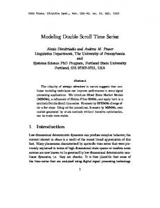
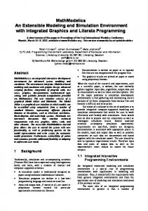
C083, Page 2 A schematic of the hot gas bypass load stand is shown in Figure 1. The different state points of the refrigerant are shown by means of a P-h diagram in Figure 2. At state point 1, superheated refrigerant is drawn into the compressor and is compressed to the discharge pressure at state point 2. After being discharged, the refrigerant goes through the discharge valves to an intermediate (condenser) pressure at state point 2’. The refrigerant then enters an oil separator. The oil is directly returned to the compressor, while the refrigerant flow is divided into two streams. One part of the flow is directly expanded to point 5, where it is still in the superheated region at suction pressure, whereas the other flow is condensed and subcooled in a condenser to state point 3. The subcooled refrigerant expands through an expansion valve into the two-phase region at suction pressure at state point 4. The two-phase refrigerant flow at state point 4 then enters a mixing chamber together with the bypassed refrigerant flow at state point 5. The ratio of the mass flow rates is controlled such that the outlet state of the mixing chamber is superheated vapor at state point 1. However, in some cases, it might be desirable to have the outlet state of the mixing chamber in the two-phase region at state point 6 and use an electric heater to control the superheat into the compressor. Two throttling valves are installed in parallel between the discharge port and the oil separator to control the discharge pressure. One is a large manual valve and the other is an accurate electronic expansion valve. The former is used for coarse control, and the later is used for fine control.
2.2 Measurement instrumentation Several pressure sensors and thermocouples are installed in the load stand to control the operating conditions and evaluate refrigerant properties throughout the cycle. The locations of these sensors are indicated in Figure 1 by “P” and “T”. Accurate pressure transducers and thermocouples are installed in the suction port and discharge port of the compressor to measure suction pressure, suction temperature, discharge pressure, and discharge temperature. A thermocouple that penetrates the compressor shell and reaches the port of chamber 2 reads the suction temperature of chamber 2. A coriolis -effect mass flow meter is installed downstream of the oil separator to measure the mass flow rate of the refrigerant. A second coriolis -effect mass flow meter is installed in the oil flow-back pipe to measure the mass flow rate of the return oil. Details about the pressure, temperature, and mass flow rate instrumentation can be found in a report written by Causey (1998). A torque meter is installed on the drive shaft of the compressor to measure the compressor’s torque and revolution. The power consumption is obtained by the product of torque and revolution.
2.3 Detailed Compressor Measurements In order to calculate the heat transfer between the refrigerant and the scrolls, the temperature distribution of the scrolls has to be known. Eight thermocouples were submerged into the half height of the fixed scroll wrap to measure the scroll’s temperature distribution. The location of the thermocouples is designed so that temperatures are obtained every π 4 radians along the scroll wrap.
2.4 Operating conditions and tests The compressor was tested at eleven operating conditions as listed in Table 1. The first five operating conditions only differ in compressor speed. These conditions were set to measure the performance of the compressor as a function of speed. Operating conditions 6 to 9 only differ in suction pressure. They were set to measure the performance with respect to the suction pressure. The last two operating conditions (10 and 11) together with operating conditions 3 and 8 only vary in discharge pressures. They were set to measure the performance with respect to discharge pressure. The compressor performance was tested at the 11 operating conditions after steady state was reached for a period of 30 minutes. The following steady-state criteria were used: the suction pressure fluctuation was not more than +30 kPa; the suction temperature fluctuation was not more than +0.5 ºC; and the discharge pressure fluctuation was not more than +50 kPa.
3. LEAKAGE AND HEAT TRANSFER MODEL VALIDATION 3.1 Leakage model validation For the investigated automobile scroll compressor, the actual values of the radial and flank leakage clearances were not known. Therefore, an iteration process was used to determine the clearance values using the measured International Compressor Engineering Conference at Purdue, July 12-15, 2004
C083, Page 3 compressor performance. In this process, heat transfer was ignored and the clearances were adjusted so that the predicted mass flow rate and power consumption were close to the measured values. However, the clearances associated with the radial and flank leakage paths may be different so they were obtained in a two step procedure. At first, the same value was assigned to both clearances and the mass flow rate was calculated for the given operating conditions. If the measured mass flow rate was greater than the calculated one, both clearance values were decreased, and if the measured mass flow rate was smaller than the calculated one, both clearance values were increased, until the calculated mass flow rate matched the measured one. In the next step, the calculated power consumption was compared to the measured one and each clearance was adjusted independently. If the measured power consumption was larger than the calculated one, the flank leakage clearance was increased and the radial leakage was decreased until both power consumptions matched while the mass flow rate was kept constant. In case that the measured power consumption was smaller than the calculated one, the flank leakage clearance was decreased and the radial leakage was increased When the calculated mass flow rate and power consumption were close to the measured ones, the clearances in the model we re treated as the real clearances for an adiabatic process. Here, ‘close’ means that the square of the errors between the calculated and measured values for all operating conditions is at a minimum. Table 1: Operating conditions for the performance measurements No.
Suction pressure (kPa) 300 300 300 300 300 200 250 300 350 300 300
1 2 3 4 5 6 7 8 9 10 11
Suction temperature (ºC) 10.7 10.7 10.7 10.7 10.7 -0.1 5.7 10.7 15 10.7 10.7
Discharge pressure (kPa) 1800 1800 1800 1800 1800 1600 1600 1600 1600 1400 2000
Compressor speed (rp m) 1000 1500 2000 2500 3000 2000 2000 2000 2000 2000 2000
3.2 Heat transfer model validation Since the temperature at the compressor’s suction port and the temperature at the entrance to the suction chamber are measured, the actual heat transfer rate due to superheating can be calculated by using equation (1), •
•
Q sch = m c p ∆T
(1)
•
where
m is half of the measured mass flow rate; c p is evaluated from thermodynamic subroutines; ∆T is the
temperature difference between the entrance to the suction chamber and the compressor’s suction port . •
Alternatively, the heat transfer rate due to superheating,
Q sch , is calculated by equation (2) in the model.
•
Q sch = hc A(Tw − T )
(2)
It was found that the value determined by equation (1) is 50% greater than the value calculated by using equation (2). This difference is due to the assumption that the flow is steady in order to calculate hc . However, the flow is disturbed by the motion of the orbiting scroll. Therefore, the real heat transfer coefficient should be greater than the one calculated by equation (2). Thus, the heat transfer coefficient used in equation (2) is multiplied by 1.5 to reflect this difference.
International Compressor Engineering Conference at Purdue, July 12-15, 2004
C083, Page 4 4. OVERALL MODEL VERIFICATION Taking leakage and heat transfers into account, the compressor mass flow rate and power consumption were recalculated. Obviously, the newly calculated mass flow rate and power consumption were less and greater, respectively, than the previous one (without heat transfer). Therefore, the values of the radial and flank clearances were adjusted one more time as described in Section 3.1 to obtain the final values used for all other simulations.
4.1 Performance validation as a function of compressor speed The comparison of the predicted and measured mass flow rates as a function of compressor speed is shown in Figure 3. It can be seen that both the predicted and measured mass flow rates increase nearly linearly with speed, and that the increments decrease as the speed increases. All experimental data points are very close to the modeling curve. The comparison of the predicted and measured power consumptions as a function of compressor speed is shown in Figure 4. It can be seen that both the predicted and measured power consumptions also increase nearly linearly with speed, and that the increments increase as the speed increases. It can also be seen that the first two experimental data points are very close to the experimental curve, while the last three data points deviate from the modeling curve. The maximum deviation is 2.9%. The comparison of the predicted and measured discharge temperatures as a function of compressor speed is shown in Figure 5. It can be seen that both the predicted and measured discharge temperatures increase with speed. Except for the last experimental point, all other experimental data points are very close to the modeling curve. The maximum difference between the predicted and measured discharge temperature (at the last data point) is 2.1 ºC.
4.2 Performance validation as a function of suction pressure The comparison of the predicted and measured mass flow rates as a function of suction pressure is shown in Figure 6. It can be seen that both the predicted and measured mass flow rates increase linearly with suction pressure. This is based on the increase of the suction density with suction pressure. The experimental data points are very close to the modeling curve except for the first data point. The maximum deviation (at the first data point) is –2.8%. The comparison of the predicted and measured power consumptions as a function of suction pressure is shown in Figure 7. It can be seen that both the predicted and measured power consumptions increase with suction pressure. Even though the specific power decreases with suction pressure, the increase in mass flow rate is dominant and overall the power consumption increases. The deviation between predicted and measured values is approximately 1% in most cases and not more than 1.5% in the worst case. The comparison of the predicted and measured discharge temperatures as a function of suction pressure is shown in Figure 8. Obviously, both the modeling and experimental discharge temperatures decrease with suction pressure. The discharge temperature is based on the suction pressure and the pressure ratio. It can be seen that the experimental data points are close to the modeling curve. The maximum deviation between predicted and measured discharge temperature is 1.2 ºC.
4.3 Performance validation as a function of discharge pressure The comparison of the predicted and measured mass flow rates as a function of discharge pressure is shown in Figure 9. It can be seen that the mass flow rate does not vary significantly with discharge pressure. In given range of pressure ratios, the actual pressure ratio is greater than the critical pressure ratio and thus, the leakage stays constant irregardless of the pressure ratio. The slight decrease in mass flow rate with discharge pressure is due to the increase in superheat, which is due to the increase in discharge temperature with pressure ratio. It can be seen that the experimental data points are close to the modeling curve. The maximum deviation is –2.3%, which occurs at the first data point. The comparison of the predicted and measured power consumptions as a function of discharge pressure is shown in Figure 10. It can be seen that both the predicted and measured power consumptions increase linearly with discharge pressure. At constant suction pressure, the pressure ratio increases as the discharge pressure increases. Since the mass flow rate is nearly constant and the specific power increases as the pressure ratio increases, the total power
International Compressor Engineering Conference at Purdue, July 12-15, 2004
C083, Page 5 consumption increases. It can also be seen that the experimental data points are close to the modeling curve. The maximum deviation occurs at the last data point and is 3.0%. The comparison of the predicted and measured discharge temperatures as a function of discharge pressure is shown in Figure 11. It can be seen that both the predicted and measured discharge temperatures increase with discharge pressure. This is based on the increas e in pressure ratio as the discharge pressure increases. It also can be seen that the experimental data points are very close to the modeling curve. The maximum deviation occurs at the second data point and is –0.4 ºC.
5. CONCLUSION This paper presents the experimentally measured performance data of an automobile AC scroll compressor. The experimentally measured mass flow rates, power consumptions, and discharge temperatures are compared to modeling result to validate the simulation model. It is found that the modeling results are close to the experimental data and the maximum deviation is not more than 3% in all cases. The validated model will be used in the next step to evaluate design changes of the compressor.
Flow Meter (I)
Oil Separator
2’
Bypass Valve
Motor
2
Flow Meter (II)
Primary Valve
T
P
4
1 T
T
5
Compressor
3
Water cooled condenser
Control Psuc
P
6
P
Heater
Mixturer
Control Tsuc
T Figure 1: Hot gas bypass load stand
International Compressor Engineering Conference at Purdue, July 12-15, 2004
P
C083, Page 6
Pressure (kpa)
2 2000 3
1500
2’
500 4
6
1
5
250
300
Enthalpy (kJ/kg)
4
210 170
Power (kw)
Mass flow rate (kg/h)
Figure 2: Load stand cycle in a pressure-enthalpy diagram
m_dot_exp
130
m_dot_model
90 50 500 1000 1500 2000 2500 3000 3500
3 power_exp
2
power_model
1 0 0
1000
Revolution (rpm)
3000
4000
Revolution (rpm)
Figure 3: Predicted and measured mass flow rates versus compressor speed
Figure 4: Predicted and measured power consumptions versus compressor speed
85 80 Td_exp Td_model
75 70 0
1000
2000
3000
4000
Revolution (rpm)
Figure 5: Predicted and measured discharge temperatures versus compressor speed
Mass flow rate (kg/h)
Discharge temperature (C )
2000
180 155 m_dot_exp
130
m_dot_model
105 80 150
200
250
300
350
400
Suction pressure (kPa)
Figure 6: Predicted and measured mass flow rates versus suction pressure
International Compressor Engineering Conference at Purdue, July 12-15, 2004
Power(kw)
2 1.9
power _exp power
1.8 1.7 150
250
350
Suction pressure (kPa)
Discharge temperatures (c )
C083, Page 1
80 76 Td_exp Td_model
72 68 150
250
350
Suction pressure (kPa)
Figure 7: Predicted and measured power consumptions versus suction pressure
Figure 8: Predicted and measured discharge temperatures versus suction pressure
2.5
140 m_dot _exp 130
120 1300 1500 1700 1900 2100
Power (kw)
Mass flow rate (kg/h)
150
m_dot _mod el
2
power_exp
1.5
power_mod el
1 1300
1700
2100
Discharge pressure (kPa)
Discharge pressure (kPa)
Figure 9: Predicted and measured mass flow rates
Figure 10: Predicted and measured power
versus discharge pressure
consumptions versus discharge pressure
Dscharge temperature (c)
85 80 75
Td_exp
70
td_model
65 60 1300
1700
2100
Discharge pressure (kPa)
Figure 11: Predicted and measured discharge temperatures versus discharge pressure
International Compressor Engineering Conference at Purdue, July 12-15, 2004
C083, Page 8 NOMENCLATURE A
heat transfer area
cp
hc
specific of R134a
heat transfers from the channel to the
heat transfer coefficient
T
mass flow rate
Tw ∆T
refrigerant temperature of the refrigerant meaning temperature of the enclosed wall
•
m
•
Q sch
difference of the temperatures
REFERENCES Causey, A.E., Groll, E.A., and J.E. Braun, “Compressor Load Stand: Commissioning and Control Strategies,” Purdue University, Herrick Labs 98-12, Report No. 3147-2, 1998. Chen, Y., Halm, N.P., Braun, J.E., and Groll, E.A., “Mathematical Modeling of Scroll Compressors Part II: Overall Scroll Compressor Modeling,” Int’l J. Refrig., Vol. 25, No. 7, 2002, pp. 751-764. Yi, F., Groll, E.A., and J.E. Braun, “Modeling and Testing of an Automobile AC Scroll Compressor, Part I: Model Development,” Proc. of the Int’l Compressor Engineering Conf. at Purdue, Purdue University, West Lafayette, IN, July 12-15, 2004.
ACKNOWLEDGEMENT The authors appreciate the financial support of Nanjing Aotecar Refrigeration Compressor Company to conduct the study and the permission to publish the two-part papers. The authors also thank Zhichao Wang and In-Su Paek for their help in conducting the experiments.
International Compressor Engineering Conference at Purdue, July 12-15, 2004