One button is pressed to request an upward moving elevator and another .... {i | i â Z+ ⧠i ⤠total number of cars}. Range ... After firing transition Assign Hall Call, the token of a placed hall-call is ... a guided direction, i.e. up or down, if the selected car is idle. ... cars are elected, the distances between the hall-call floor and.
Int'l Conf. Software Eng. Research and Practice | SERP'15 |
183
Modeling Elevator System With Coloured Petri Nets Mohammed Assiri, Mohammed Alqarni and Ryszard Janicki Department of Computing and Software McMaster University Hamilton, Ontario, Canada L8S 4L8 Abstract— A fairly general model of the elevator system is presented. Coloured Petri Nets (CPN) and CPN tools are adopted as modeling tools. The model, which is independent of the number of floors and elevators, covers different stages of the elevator system in substantial detail. The model assists simulation-based analysis of different algorithms and rules which govern real elevator systems. The results prove the compatibility and applicability of this model in various situations and demonstrate the expressive power and convenience of CPN. Keywords: Formal Specification, Elevator System, Software Specification Benchmarks, Coloured Petri Nets
1. Introduction The elevator system is one of the software engineering benchmarks which are frequently used to test the expressive power, readability, and convenience of various formal specification techniques [1]. Petri Nets is one formal specification technique. In [2] and [3], dynamic scheduling of the elevator system was modeled by Petri Nets, and hybrid Petri Nets. Timed Petri Nets, Abstract Petri Nets and Elevator Control Petri Nets were used in [4], [5], and [6] respectively. Furthermore, the elevator system was modeled by Coloured Petri Nets in [7], and Timed Coloured Petri Nets in [8] and [9]. Nevertheless, all of these previous models are either static or dependent on a particular number of elevators and floors (often one place was required for each elevator car), the concept of colour as a data type was not fully utilized, or other formalisms such as UML were substantially involved. Our model is independent of the number of floors and elevators and covers different stages of the elevator system in substantial detail. We believe our model is flexible enough to be adapted to different algorithms and rules, and may eventually evolve into a ’standard’ formal model of the elevator system.
2. The Elevator System Elevator systems are an integral aspect of buildings from the point at which they are first designed. With high-rise buildings being the typical candidate for elevator systems, such systems are usually very complex. Multiple elevators must be controlled by a centralized control mechanism. The
complexity of these elevator systems arises from factors such as scheduling needs, resource allocation, and stochastic control, to name a few. Handling these jobs usually results in systems behaving as discrete event systems [10]. The elevator system is usually defined as follows [1]: An elevator system is to be installed in a building with m floors and n cars. The elevator and the control mechanisms are supplied by the manufacturer. The internal mechanism of an elevator system is assumed (given). The problem concerns the logistics of moving cars between floors according to the following constrains: a. Each elevator’s car has a set of buttons - one for each floor. Pressing these buttons signals the elevator to move to the corresponding floor. b. On the wall outside the elevator each floor has two buttons (with the exception of the ground and the top floors). One button is pressed to request an upward moving elevator and another button is pressed to request a downward moving elevator. If both buttons are pressed, then each direction is assigned to a different car. c. When an elevator has not received any requests for service, it should be held at its parking floor with its doors closed until it receives further requests. d. All requests for elevators from floors (i.e. hall calls) must be serviced eventually. The applied algorithm controls the priority of floors. e. All requests for floors within elevators (i.e. car calls) must be serviced eventually, with floors usually serviced sequentially in the direction of travel. f. Each elevator’s car has an emergency button which when pressed causes an alarm. The elevator is then deemed "out of service". Each elevator has a mechanism to cancel its "out of service" status. Our model is based on the above description.
3. Coloured Petri Nets Coloured Petri Nets (CPN), first proposed in [11] and later substantially modified and enhanced in [12], are an extension of Petri Nets which are often used to model behaviours of rather complex systems. CPN have preserved the useful properties of Petri Nets while at the same time extending the initial formalism to allow for distinction between tokens. Coloured Petri Nets (CP-nets or CPNs) is a graphical language for constructing models of concurrent systems and
184
Int'l Conf. Software Eng. Research and Practice | SERP'15 |
analysing their properties. CP-nets is a discrete-event modelling language combining the capabilities of Petri Nets with the capabilities of a high-level programming language. Petri Nets provide the foundation of the graphical notation and the basic primitives for modelling concurrency, communication, and synchronisation. Coloured Petri Nets allow tokens to have a data value attached to them. This attached data value is called token colour. Although the colour can be of any arbitrarily complex type, places in CPNs usually contain tokens of one type. This type is referred to as the colour set of the place. A semi-formal definition can be given as follows: A Coloured Petri Net is a tuple: N = (P, T, A, Σ, C, N, E, G, I) where: • P is a set of places. • T is a set of transitions. • A is a set of arcs. • In CPNs sets of places, transitions, and arcs are pairwise disjoint P ∩ T = P ∩ A = T ∩ A = ∅ • Σ is a set of colour sets defined within CPN model. This set contains all possible colour, operations, and functions used within CPN. • C is a colour function which maps places in P into colour in Σ. • N is a node function which maps A into (P × T ) ∪ (T × P ). • E is an arc expression function which maps each arc a ∈ A into the expression e. The input and output types of arc expressions correspond to the type of nodes which the arc is connected to. • G is a guard function which maps each transition t ∈ T into guard expression g. The output of the guard expression should evaluate to Boolean value true or false. • I is an initialization function which maps each place p into an initialization expression i. The initialization expression must evaluate to a multiset of tokens with a colour corresponding to the colour of the place C(p). CPN support hierarchical modeling and are equipped with a modeling language called CPN ML which is based on the standard functional programming language ML. There are a variety of tools that can be used. In this paper the tools from [13] have been used. For more details and theory of CPN, the reader is referred to [14].
4. CPN-based Modelling of Elevator System Due to the complexity of the elevator system and the desired flexibility of the structure, the proposed model is
composed of five major interconnected but independent submodels. These sub-models include the car-structure submodel, the hall-call sub-model, the car-call sub-model, the system-cycle sub-model, and the hierarchical parkingoptimizer sub-models. The functions and connections between sub-models are described as follows: The car-structure sub-model represents the elevator’s cars. It is at the centre of all other sub-models that concurrently control the elevator’s cars. Typically, an elevator car is requested by two types of controls: either a hall-call or a car-call. As the names suggest, a hall-call is placed by pressing a button located in the hallway of a given floor while a car-call is place by pressing a button inside the car of the elevator. When a hall-call is placed, by relying on algorithms the hall-call sub-model will assign the hall-call to the appropriate car of the car-structure sub-model. Similarly, the car-call sub-model coordinates the placed car-calls with the cars of the car-structure sub-model. The system-cycle sub-model operates the cars of the carstructure sub-model to service the requested calls. Finally, the parking-optimizer sub-models reduce the waiting time between the placing hall-call and the arrival of the assigned car by constantly electing the holding floors of the idle cars.
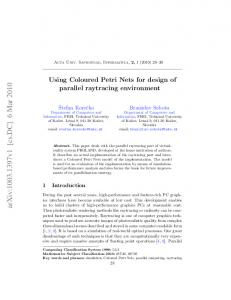
4.1 Car-Structure Sub-Model This sub-model (Figure 1) consists of just two places Cars and Database that also belong to other sub-models. The first place has the colour set Cars, which is a record colour set or the Cartesian product of the sets described in Table 1. The second place has the set of colours Database (defined in Table 2). In principle, this is a list of all the necessary information about the states of cars. This list is used by the algorithms of the hall-call sub-model. Both places are initialized dynamically by the functions initialize cars and initialize database respectively. � ���� �� ������� ���� ����
� ���� �� � ������ �� �������
�������
����
�������
Fig. 1: The Car-Structure Sub-Model Table 1: The definitions of colour set Cars Colour Sets
Definitions
Car ID Range Status Desired Floors Call Issuer INT Cars
{i | i ∈ Z+ ∧ i ≤ total number of cars} {r | r ∈ Z+ ∧ lowest f loor ≤ r ≤ highest f loor} {up, down, emergency, idle, out of service} {[l] | l ∈ Range} {request, system, non, reservation} {n | n ∈ Z} { (car id, current floor, status, parking floor, desired floors, call issuer) | car id ∈ Car ID, current floor ∈ Range, status ∈ Status, parking floor ∈ Range, desired floors ∈ Desired Floors, call issuer ∈ Call Issuer}
Int'l Conf. Software Eng. Research and Practice | SERP'15 |
Table 2: The definition of colour set Database Colour Sets
Definitions
Car Info
{(current floor, status, destinations, car id) | current floor ∈ Range, status ∈ Status, destinations ∈ Desired Floors, car id ∈ Car ID} {[d] | d ∈ Car Inf o}
Database
In the colour set Cars, the parking floor indicates which floor the car is held when idle. The initial value of the parking floors is calculated in general by the following equations: Floor No. = (highest floor no. − lowest floor no.) +1 Scope = | floors no. ÷ numbers of cars | Scope’s Head = ((scope * car id) − (scope − 1) + (lowest floor no. −1)) Scope’s Tail = (scope ∗ car id) + (lowest floor no. −1) Thus, a parking floor of a car is assigned optionally by either Scope’s Head or Scope’s Tail. Otherwise the parking floor may be typed manually for each car, especially in cases when the above equations are impractical. The other elements of the colour set Cars are selfexplanatory.
4.2 The Hall-Call Sub-Model This sub-model assigns a hall-call to the most appropriate car based on the applied given algorithms (which are subject to changes and replacements). Furthermore, the model generates hall-calls from arbitrary floors and a selected floor in order to facilitate efficiently the examination of various rules and algorithms during the simulation-based analysis. The processing of hall-calls is initialized from place requested call where each token represents a placed hallcall of colour set Hall Call. Every token has an appropriate direction and a floor number where the hall-call was placed. Assigning a hall-call to a car requires the firing of transition Assign Hall Call. Transition Assign Hall Call is enabled if and only if its guards, which represent appropriate rules, are holding. The specific rules that must be satisfied are comprised of the following: 1) the selected car is either idle or traveling toward the direction of the hall-call; 2) the selected car is not reserved; and 3) the selected car is elected by the applied algorithm. After firing transition Assign Hall Call, the token of a placed hall-call is removed from place requested call and assigned to the desired-floors list of a selected car in place Cars with a guided direction, i.e. up or down, if the selected car is idle. Two algorithms - namely the nearest-car algorithm [15] and the scope algorithm which process the assignment of hall calls to cars - are implemented separately to examine the model’s ability of adopting various algorithms and rules.
185
Place Database facilitates the adoption of multiple different algorithms that require simultaneous access to all cars’ states; hence, other algorithms can easily be adopted. Table 3: The definition of colour set Hall Call Colour Set
Definition
Hall Call
{(hall call floor, status) | hall call floor ∈ Range, status ∈ Status}
The nearest-car algorithm starts by analysing the token of place Database from Table 2. First, the cars with proper status (i.e. cars that are travelling toward the hall call request or that are servicing no calls) are extracted from the token. Each car is represented by a single tuple, so selection of cars occurs by extracting appropriate tuples. Once the proper cars are elected, the distances between the hall-call floor and cars’ current floors are calculated by the absolute value of the difference between current floors and the hall-call floor for each car. Accordingly, the hall-call is assigned to the car with the minimum distance to the hall-call floor. Additionally, in this paper we have improved the nearest-car algorithm by further calculation of time consumed by the car’s stops between the hall-call floor and the car’s current floor. Thus, travel times plus the number of served calls between car’s current floor and the hall-call floor are calculated for each car. Based on this, the car with the expected minimum waiting-time is assigned to serve the hall-call. The scope algorithm is usually employed in express elevators and sky-lobby floors where each car is forced to serve a specified range of floors with an allowance of transit floors. We implement the scope algorithm as extra guards on transition Assign Hall Call. For instance, a guard that identifies the range of floors for each car is written as: H ≤ A ≤ T. where: H = the head floor of the car’s scope A = the answered hall-call floors T = the tail floor of the car’s scope The hall-call model also allows for a simulation-based analysis of different algorithms by controllably producing two classes of floors’ numbers: arbitrary, where numbers range from lowest to highest floors; and an identified number of a specific floor that is requested repeatedly. Some parameters (in Table 4) are defined for controlling the production of hall calls. Moreover, a produced floor’s number is associated with a direction based on the two rules. First, a floor’s number equates the highest floor that is associated restrictedly with the down direction. Conversely, a floor’s number equates the lowest floor that is associated restrictedly with up direction. The other floors’ numbers are associated non-deterministically (modeled as a uniformly distributed random choice) to upward or downward direction.
186
Int'l Conf. Software Eng. Research and Practice | SERP'15 |
�� �!!��!$$'(�� #*"��'(
�'#��*�'��#����
���
#
��!��(����#�$" ��*"��'
�$*#)�' #��
(�!��)����!$$'
��
(�!��)�� �!$$'�(�#*" ��#��
'#�'�#�$"��
#�+���!!
� �'��*�'�����
#�+���!!
��!��(�
�!$$'�( #*"��' ��#�� #�+���!!
� ���
���
+�)��� ��#�'�)$'(
((��# ��'��)�$#
�
��
�(#���'�#�+���!!�
�
!$�
���
'�&*�()�����!! �!!� �!!
��(#����!!��*�'� ���!!���!!���'�����
�!!� �!!
��!!���!!
��!!���!! �#�)��!�-����'(��
��' ((��#� �!!� �!!
�'(
�'( (#�����!! ���'���!!���!!� *%���� ���!!���!!� �����'�
��!!���!!
�'(
�� �#�)��!�-����)���(���
��)���(� ��)���(�
�' ��,( �!!� �!!
��)���(�
Fig. 2: The Hall-Call Sub-Model Table 4: The Parameters of The Hall-Call Sub-Model
Table 5: The definition of colour set Specific Floors
Parameters
Legal values
Colour Set
Definition
Producing mode Times of finite hall calls The most requested floor Duplication of requested floor The applied algorithm Production’s pause number
{f inite, inf inite} {y | y ∈ Z ∧ 0 ≤ y} {r | r ∈ Range} {d | d ∈ Z ∧ 0 ≤ d} {minimum waiting, nearest, scope} {p | p ∈ Z+ }
Specific Floors
{(car id, specific calls, repeated times) | car id ∈ Car ID, Specific calls ∈ Desired Floors, repeated times ∈ Z}
4.3 The Car-Call Sub-Model This sub-model provides a coordination between the cars and the car-calls. Additionally and similarly to the hallcall sub-model, this sub-model includes generators for both arbitrary and identified floors’ numbers. The coordination between cars and requested car-calls are represented by tokens in place car call with the colour set Range, which is a floor number in the range between the lowest and the highest floor. Placing the car-call in a car demands firing transition Coordinate which is enabled when its guards are satisfied in respect to the producing mode’s state and the applied algorithm on the hall-call sub-model. For instance, in the scope algorithm the car serves only within the floors of the car’s defined scope. After firing transition Coordinate, the placed car-call is removed from place car call and inserted into the car’s desired-floors list with an appropriate direction if the car is idle. Similarly, the list of the specified calls, in place specific floors’ num by colour set Specific Floors (see Table 5), is also merged.
The car-call model also features two mechanisms that produce arbitrary car-calls where each call is placed individually into a car and a list of specified calls are placed entirely to each available car by transition Coordinate. Table 6 outlines some of the parameters of car control. Table 6: The Parameters of The Car-Call Sub-Model Parameters
Legal values
Producing mode Times of finite car calls Most desired floors Frequency of desired floors Production’s pause number
{f inite, inf inite} {x | x ∈ Z ∧ 0 ≤ x} {[f ] | f ∈ Range} {d | d ∈ Z ∧ 0 ≤ d} {p | p ∈ Z ∧ 0 < p}
4.4 The System-Cycle Sub-Model This sub-model deals with the system cycle of the elevator’s cars during the operation of the elevator system. Each elevator’s car experiences three separate stages of maintenance, arrival, and transition (see Figure 4). Furthermore, the system-cycle sub-model has basic parameters which are very
Int'l Conf. Software Eng. Research and Practice | SERP'15 |
��
187
�$�!��'�$��!����
�
!
������""$%�� !' ��
%$�����%�� �""$�%��' ��$
�"'!&�$ !�
��
�
��
$!�$�!�" ��
� )�&��� ��!�$�&"$
��$�����
��
��!��
� ��""$���'�$����$��������$�%��!�)�������
!�)�����
��
�!�&����*��%��""$%��
%�
%#������ ��""$%��!'
""$��!�&� #���������% ���$�%�� ��
'#����� �!�)������ �����$�%��
%!����������$� !�)������%��
��$
�!�&����*����&���%��� ��&���%� ��&���%�
��$�����
��&���%�
�"�
�
%$%�
$�#$"�'���%��
�$�#��'�$� �%����$���$�������
�!�&����*���"���
�!�&����*����$%��
�
%$�
%$�#������� �""
%$�$���(����$���$������ !�)������%��
��#$"�'��
��$�����
�$� ���%
�
��$
Fig. 3: The Car-Call Sub-Model
convenient for simulation-based analysis (defined in Table 7). Table 7: The Parameters of The System-Cycle Sub-Model Parameter
Legal value
Car’s number Lowest floor number Highest floor’s number Restart cars automatically
{i | i ∈ Z+ } {n | n ∈ Z+ ∧ n < highest f loor} {m | m ∈ Z ∧ lowest f loor < m} {yes, no}
The maintenance stage models the suspension of a car which is caused either by an emergency case when the car’s emergency button is pressed, or by an operation failure case when an error occurs during the execution of the elevatorsystem model. The suspension is the result of firing transition Maintain which has the highest priority in the entire model (i.e. when it is enabled, all other transitions in the model are blocked). Therefore, when the status of a car is "emergency" or "out of service", then transition Maintain fires and the car’s token is transferred temporarily from place Cars to place out of service. At this point the token in place Database is updated accordingly. Hence, the car is not accessible by any other sub-models that have no access to place out of service. Later, a pending car can be restarted either automatically or manually based on the value of parameter restart cars automatically. If it is assigned to "yes", then transition Restart is enabled immediately. However, if the parameter is set to "no", then restarting pending cars requires manually altering the status of the car to a different value other than "emergency" or "out of service". In both cases, firing of transition Restart results in a car’s token being returned to place Cars and place Database being updated; therefore, the car is accessible by other sub-models. The transition stage describes the process of moving
elevator cars between floors. This is modeled by the firing of transition Transfer, which is enabled if transition Maintain is not, the car’s desired-floors list is not empty, and the car’s current floor matches no calls of the desired-floors list. After firing transition Transfer, the car’s token is updated as follows. If the car’s desired-floor list has calls beyond the car’s current floor, it continues shifting in the same direction. Otherwise its direction is reversed. In both cases, the token in place Database is updated accordingly. Once a car reached its desired destination, it is in the arrival stage. At this stage, transition Arrive is enabled if transition Maintain is disabled and the car’s current floor matches a requested call of the desired-floors list. After firing transition Arrive, car’s token is updated by dropping the requested floor from the car’s desired-floor list. Additionally, the car’s state is set to one of three cases. If the car’s desired-floor list has more calls, then it continues serving the requested calls. Otherwise, the car is set to idle if the car’s current floor agrees with its parking floor or alternatively the car is dispatched to its parking floor with an appropriate direction. Finally, place Doors represents doors’ operations. Since such operations are almost trivial, they have been included in one place that can be converted into an hierarchical sub-model to show all of the doors’ activities.
4.5 The Parking Optimizer Sub-Models Holding idle cars on or near floors where most hall-calls are placed substantially improves passenger satisfaction and the system’s energy usage and efficiency [15]. Therefore, cars are initially distributed in fair distances between the lowest and highest floors. Subsequently, the parking optimizer sub-models continuously analyse the placed hallcalls and then assign the elected floors to the cars. The parking optimizer models include the election sub-model
188
Int'l Conf. Software Eng. Research and Practice | SERP'15 |
��������!���������� ������ �����
����
����
�������������������
��������!������������
��������������� ����������� ����
���� �
���
�������� �������� ��
��������
��������� ����
���� ������
���
���������������
���
��������������
��
��������������
��������!�������� ��� �������
�������� ��������
���� ����
���
�
���� ������� �����
��
������������ ��������������
��������!������������ ��������
���������� ��� ��������
�������� �������������
����
������
��� ��
������� ��������
Fig. 4: The System-Cycle Sub-Model
and the position sub-model. In Table 9, the definitions of the parameters which facilitate the control of the parking optimizer model are presented. Table 8: The Parameters of The Parking Optimizer SubModels Parameters
Legal values
Parking system state Analyzing hall calls
{”enable”, ”disable”} {x|x∈Z}
All models of the parking optimizer sub-model are selfexplanatory. However, it is also important to first note that the procedures of all models must be sequential. Therefore, some transitions have priorities which are represented by numbers that appear in the bottom-left corner of each transition. The value of these numbers implies the order of enabled transitions. Second, the fusion place Lock of the system (Lock Sys) is functionally similar to an inhibitor arc. If there is a token in a place, an inhibitor arc disables a transition (see [16]). For example, if Lock Sys has the value "0", then transition Count Call is disabled: this locks the system from analysing more hall calls. This place is critically important because when a car is in the maintenance stage of the system-cycle sub-model and not accessible, then the parking optimizer sub-models cannot successfully assign all elected floors. Consequently, the parking optimizer sub-models are suspended until the ongoing maintenance is completed. After election sub-model (in Figure 5(a)) counts the
repetition of all placed hall-calls and then nominates the floors where most hall-calls have been repeatedly placed, the position sub-model (in Figure 5(b)) alters the cars’ parking floors with respect to their scopes. This process works to approximately guarantee fair distances between cars to reduce the total wait times. Table 9: The Colour Sets of The Parking Optimizer SubModels Colour Sets
Definitions
Floors Statistics Scope
{(floor,times) | floor ∈ Range, reputation ∈ Z} {(scope id,prev,next,elected floors) | scope id ∈ Car ID, prev ∈ Z, next ∈ Z, elected floors ∈ INT List} {(scope id,floors’ number) | scope id ∈ Car ID, floors’ number ∈ Z} {(floor id,floor’s number) | floor id ∈ Car ID, floor’s number ∈ Range}
Scope Statistics Identified Floor
5. Analysis Two analyses techniques were applied. The first technique is the reachability analysis by means of the State Space tool [17]. This tool verified and generated an automatic report. The proposed model has dead markings that occur in cases such as a placed hall-call with no available car. Transition Maintain and transition Restart are dead transitions which indicate no operation failure of the proposed model. The second technique is the simulation-based analysis by means of CPN Tools. Although this technique is flexible, it is also time-consuming. However, the proposed model was
Int'l Conf. Software Eng. Research and Practice | SERP'15 |
!'!�-! �"'))+, �.-
� !'!�-! �"'))+ �).(-!+ ��� ��(#! (
%
simulated repeatedly with different settings, and the entire definition of the system was achievable.
.* �!"��-'�(�
��"'))+�",�
�!'!�-�#.�+ �-'�(�",��
�'!�-��'))+
.* �*���(�%�-'�
� -'
.* �-!�'%,-�-'�(�
",
��� ,)+-! '%,-
,)+-�+!�.+,%)(�",�-'�
",
�/!!*!��(!'!�-! ��'))+,
��( % �-!� "'))+, �'))+,��-�-%,-%�,
�����%,-
-' ",
�,)+-�#.�+ �(�",��
�)+-��'))+,���!�.+,%)(
%
(
.* �-!�,-�-%,-%�,�",�
",
��
���
(
(�
"'))+,� ,-�-%,-%�,
�)�&��0,
��� ��).(-�#.�+ �$�''���''�",�(�%��
%(%-%�'%1!�,-�-%,-%�,��
��
*+)�!,,! ��''��).(-!+
�'))+,��-�-%,-%�,
%
",
�).(-�$�''���''�",�
).(-� �''
$�''���'' �+&��0, ��''� �''
(a) The Election Sub-Model �,.2�%1 ." �/�0�� �"#*0&$5��.#2&+1/ ��!+,#
&"#*0&$5�,.2�/�0�
�
/
!),( ,.2
�"#*0&$5��#40 ��!+,#
0
.#0&)#/
�!+,#
/
�*40�%1 ."�/�0��
0
&"#*0&$5�*40�/�0�
�!+,#��0 0&/0&!/
!),(� +."#./
!),( *40
�!+,#
�!+,#
/ !+1*0�$(++./�/�
�#!&"#��+/&0&+* /
&��
"#!&"#�/�
&
�*����
��� �+1*0��!+,#�/� �(#!0#"��(++./
�+!'��5/
*
���
1*(+!'/5/�&�
/
&
� (0#.�%1 ." �! .�$�� �(0#.�� .�/ �� .'&*%��(++. .#�&*&0& (&6#�&�
&*&0& (&6#�/!+,#�� /!+,#/ �!+,# �/!+,#�%1 ." �/�$(++.��
/
&"#*0&$5�/�$(++.�
*#3 ,+/&0&+* �"#*0&$&#"��(++. $
�� ! .
(0#.�! .�$�
�"#*0&$5��!+,# &*&0& (&6#�! ./��
$(++.
� � ./ ./ � ./
#(#!0#"�$(++./ �*
189
� *%#
(b) The Position Sub-Model
Fig. 5: The Parking Optimizer Sub-Models
6. Conclusion We have provided a fairly general CPN-based model of the elevator system. The model covers various aspects of the elevator system and is divided into five sub-models that can be analyzed independently. Such division allows for easier tracking of errors and faults in the elevator system. The flexibility of the model allows for easy adaptation of different algorithms and rules depending on the actual needs.
Acknowledgements The first author was supported by Prince Sattam bin Abdulaziz University, the second author was supported by the Ministry of Education of Saudi Arabia, while the third author acknowledges partial support by NSERC Discovery Grant of Canada.
References [1] C. Ghezzi, M. Jazayeri, and D. Mandrioli, Eds., Fundamentals of Software Engineering, 2nd ed. Pearson Prentice Hall, 2003. [2] C.-H. Lin and L.-C. Fu, “Petri net based dynamic scheduling of an elevator system,” in IEEE International Conference on Robotics and Automation, vol. 1, 1996, pp. 192–199. [3] Y.-H. Huang and L.-C. Fu, “Dynamic scheduling of elevator systems over hybrid Petri net/rule modeling,” in IEEE International Conference on Robotics and Automation, vol. 2, 1998, pp. 1805–1810. [4] Y. C. Cho, Z. Gagov, and W.-H. Kwon, “Timed Petri net based approach for elevator group controls,” in IEEE/RSJ International Conference on Intelligent Robots and Systems, vol. 2, 1999, pp. 1265– 1270. [5] E. S. Etessami and G. S. Hura, “Abstract Petri net based approach to problem solving in real time applications,” Fourth IEEE Region 10 International Conference, pp. 234–239, 1989. [6] Y. Ahmad, Farooq and Fakhir, Ilyas and Khan, SherAfzal and Khan, “Petri net-based modeling and control of the multi-elevator systems,” in Neural Computing and Applications, vol. 24. Springer London, 2014, pp. 1601–1612. [7] J. M. Fernandes, J. Baek Jorgensen, and S. Tjell, “Requirements Engineering for Reactive Systems: Coloured Petri Nets for an Elevator Controller,” in 14th Asia-Pacific Software Engineering Conference, 2007, pp. 294–301. [8] D. Liqian, Z. Qun, and W. Lijian, “Modeling and analysis of elevator system based on timed-coloured Petri net,” in Fifth World Congress on Intelligent Control and Automation, vol. 1, 2004, pp. 226–230. [9] J. Ye, J. Li, F. Deng, and C. Wang, “Simulation of the intelligent control circuit based on Petri net,” in 6th International Conference on Computer Science & Education, 2011, pp. 66–69. [10] P. J. Ramadge and W. M. Wonham, “The control of discrete event systems,” in Proceedings of the IEEE 77.1, 1989, pp. 81–98. [11] K. Jensen, “Coloured Petri Nets and the Invariant Method,” Theoretical Computer Science, vol. 14, no. 3, pp. 317–336, 1981. [12] K. Jensen, Coloured Petri Nets. Springer, 1994. [13] CPN Tools AIS Group, The University of Technology, Eindhoven, The Netherlands, http://www.cpntools.org. [14] K. Jensen and L. M. Kristensen, “Coloured Petri Nets Modelling and Validation of Concurrent Systems.” Berlin: Springer, 2009. [15] G. Barney, Elevator Traffic Handbook: Theory and Practice. Taylor & Francis, 2003. [16] R. Janicki and M. Koutny, “Semantics of inhibitor nets,” Information and Computation, vol. 123, no. 1, pp. 1–16, 1995. [17] K. Jensen, S. Christensen, and L. M. Kristensen, “CPN Tools State Space Manual,” Department of Computer Science, Univerisity of Aarhus, 2006.